| KIT #: | |
| PRICE: | $ |
| DECALS: | |
| REVIEWER: | Michael Rohde |
| NOTES: |
| HISTORY |
The P 6 E was the ultimate result of a long line of Curtiss Hawk designs and this particular model was the result of combining a series of design features based on the manufacturers in-house experience.
 In July 1931
the USAAC ordered forty six production aircraft to equip the 17th Sq. stationed
at Langley Field Virginia and the 33rd and 94th Pursuit Sq. at Selfridge. 17th
Sq was the only unit which had exclusivly P6 E Hawks on strength.
In July 1931
the USAAC ordered forty six production aircraft to equip the 17th Sq. stationed
at Langley Field Virginia and the 33rd and 94th Pursuit Sq. at Selfridge. 17th
Sq was the only unit which had exclusivly P6 E Hawks on strength.
The P 6 E had favourable handling characteristics , however ,at least twenty seven of the forty six production aircraft were lost in accidents. The P 6 E served throughout the 1930's to be officially retired from USAAC service in September 1939. The majority of surviving aircraft were donated to civilian aviation schools as non operational training airframes. At least two P6 E's survived in USAAC service until 1942 .
It is important to mention that in 1932 Captain Ruben C. Moffat flew a modified P6 E with a supercharged Curtiss V 1570 C Conqueror engine on a record flight from Dayton Ohio to Washington DC achieving a top speed of 266 mph at an altitude of 25000 ft.
| THE KIT |
The kit is a multi media kit consisting of three frames molded in grey plastic holding thirty three parts in all. A bag of resin parts ( twenty in total) are provided for the cockpit, propeller hub, machine gun barrels , radiator. exhausts and a belly tank. The clear part for the wind screen is vac formed and there are two of these in the box.
 The
instructions in places are not very helpful and one has to figure out how bits
go together. There are 12 steps as per instructions and a rigging diagram is
included. The decal sheet is very nice indeed. The decals themselfes are quite
thin,good in colour and register well.
The
instructions in places are not very helpful and one has to figure out how bits
go together. There are 12 steps as per instructions and a rigging diagram is
included. The decal sheet is very nice indeed. The decals themselfes are quite
thin,good in colour and register well.
Decal options are for: Group Commander , 17th Pursuit Sq 1932 Langley Field Virginia, 17th Pursuit Sq 1932 Langley Field Virginia. 94th Pursuit Sq 1936 Selfridge Harrison Michigan, 36th Pursuit Sq 1936 Selfridge Harrison Michigan
The individual parts do need a lot of work due to mold shift and some substantial flash. There are no locator pins and the joints for the lower wings vertical and horizontal tail planes are uneven and need adjustment. I also detected a couple of accuracy problems. The horizontal tailplanes are different in size and the fuselage keel surfaces are not shaped identically. The left side has a distinct curve to the rear , whereas the right hand side is straight.
| CONSTRUCTION |
I began with separating all parts from their sprues and started the tedious task to get rid of flashes and sink marks and tried to fix the steps caused by mold shift. This could be found esp. on the upper and lower wings and, more unfortunately so, on cabane and N struts. As one can imagine , this took considerable time and a less patient modeller would have canned this project at this stage. In short-- every single part in the kit needed work. The resin parts in comparison were rather easy to deal with.
So --- as per plan-- I continued to build the cockpit first. Tricky were the tiny parts ie the controls and esp the rudder bars.Care had to be taken to separate these from the casting blocks.
 I painted
all the components before assembly and dry fitted the whole assembly into the
fuselage halfes to make sure that there will be no problem when glueing the
fuselage shells together.. The same went for the radiator block and the
exhausts. I had to cut and grind in places to ensure a positive fit .
I painted
all the components before assembly and dry fitted the whole assembly into the
fuselage halfes to make sure that there will be no problem when glueing the
fuselage shells together.. The same went for the radiator block and the
exhausts. I had to cut and grind in places to ensure a positive fit .
After a good fit was ensured I glued the cockpit tub , radiator and the exhausts into place with super glue and joined the fuselage halfes. The seams nedded some filler and careful sanding.Rescribing of panel lines had to be done in places.
The propeller blades needed a good deal of finishing work before these could be glued onto the resin hub. I drilled recesses for the blades and took great care to align the pitch of all three blades evenly using a slower setting super glue which gave me time to adjust the angle. A shaft for the propeller needed to be scratchbuild using plastic rod.
The next step was to attach the lower wings , horizontal and vertical tail plane.A dihedral of 2 degrees is referred to in the instructions. The upper wing consists of two halfes and , as already mentioned , quite a bit of work was to be done using putty , sanding an polishing to get a clean leading and trailing edge.
This was followed by attaching the landing gear legs and – after the glue had set – fitting the spats. The version I decided on had not the fully spatted wheels. Again- the fit was not really satisfying and I had to use putty and sand paper to tidy up gaps. The wheels were test fitted to the spats before I joined these with the legs and here too quite a bit of adjustment was required to fit the wheels neatly into the spats.
At this point I carefully drilled all the tiny holes
for the rigging attachment points.( all thirty eight of them) The rigging
diagram in the instructions is not quite correct .You have to refer to the
online walk around photos to make sure that you drill the holes in the right
places. This was especially important in regards to the rigging wires from the
upper wing down to the lower mid wing root and the seam on top of the landing
gear legs ( not all of them to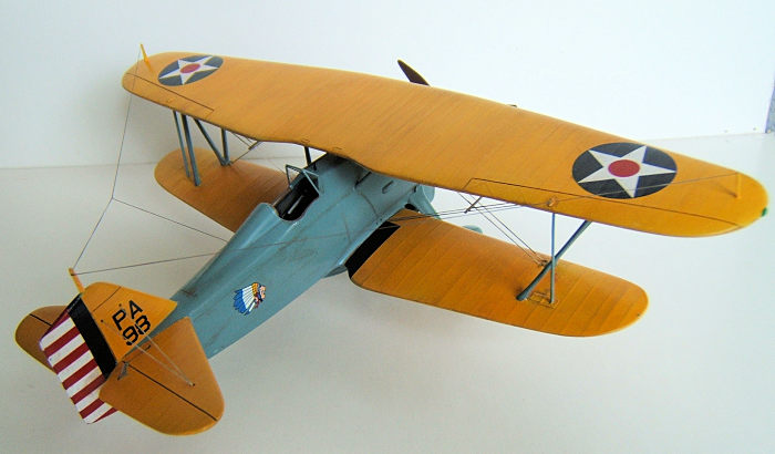 the mid wing root as per plan)
Once that was out of the way I arrived at the most difficult part of the build. The struts and their proper alignment between upper and lower wing. The instructions give us a diagram on how to set these struts at the correct angle. That is all nice an dandy provided that the dimensions of the struts ( ie length) are correct. Initially I trusted that this would be the case and continued to set up and glue the struts into place and tried as best as I could to establish the angulation as indicated. After the glue had set I test fitted the upper wing and here we go :The cabanes did not align with the holes given in the mold. The N struts 'kind of 'did. So what now???
I had no other choice but to re drill the seats for the cabanes and fill the existing holes with putty. The locator pins on the outer struts were not clearly refined either and too big to fit into the holes provided. So drilling had to be done to get these to fit as good as possible. One surprise was that one of the N struts was short by about 2 mm and I was forced to build up the missing part with bits of plastic card and carefully cut and sand this into shape. Not a easy task considering that the strut is already glued into place and rather thin and bendable on top of it. But I managed in the end and went back to another test fit of the upper wing using masking tape to hold things together. Now guess what.!!!
Looking at photos of the real thing and my model I found that the distance between upper and lower wing is a tat smaller than in reality. To be honest, at this point I thought – so be it – I am not doing some major surgery for the sake of getting this right. The build so far was already taxing my endurance so I was only too ready to compromise .
Another problem was the wind shield. The kit part is totally useless and I made one using 0.4 mm Evergreen clear polystyrene sheeting. This was achieved by cutting three individual pieces and carefully trimming them into shape to fit the curvature of the fuselage decking before glueing them together. Must say that I was quite happy with the result. The gunsight is also scratch build from polystyren rod.
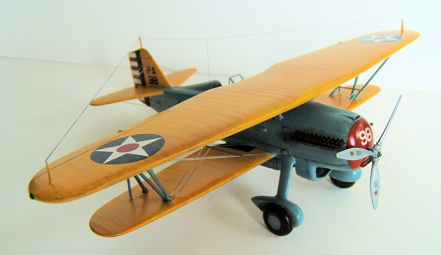
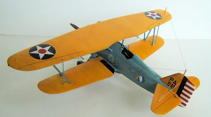
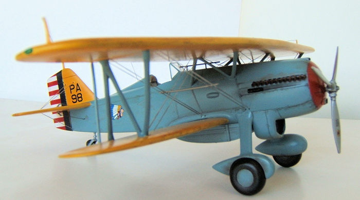
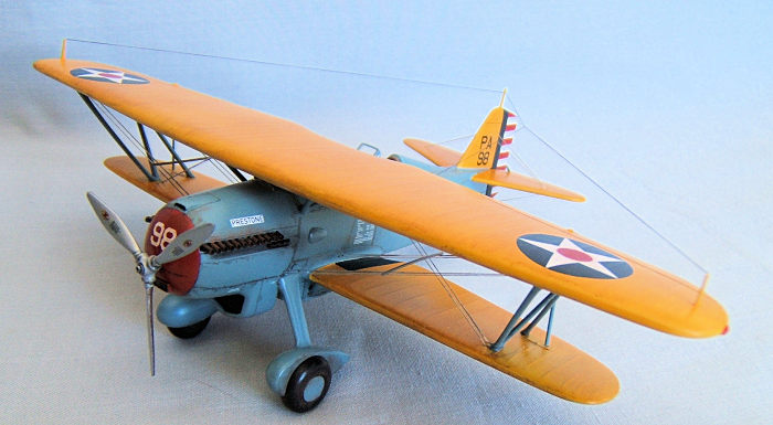
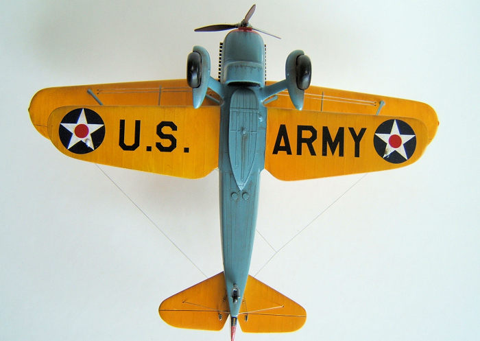
So far so good . I could now proceed to getting this beasty painted. I liked the colourful scheme of the 94 Pursuit Sq being US light blue and chrome yellow wings and tail plane with a red nose.
| COLORS & MARKINGS |
 Painting had
to be done in stages and as you can imagine there was quite a bit of masking
tape necessary to achieve this.. Weathering was done using a acrylic wash and
some pastels.
Painting had
to be done in stages and as you can imagine there was quite a bit of masking
tape necessary to achieve this.. Weathering was done using a acrylic wash and
some pastels.
Since the upper wing was painted separately the pre rigging after the painting was done starting with the lower wing/ fuselage and finishing off after the upper wing was aligned with the rest of the model, secured with masking tape and then glued together with super glue.
The gun sight was glued into place before the upper wing went on. Needless to say that extra care had to be taken not to break or bend this fragile item in the process.
Important to mention that all the holes had to be re drilled before rigging could commence to remove any paint residue. If this is not done the super glue will soften the paint and create a sticky substance which does not want to set properly and you will have a hell of a time to hold the rigging with fine tweezers and hope that that stuff will bind. You don't want that. If done the right way the ends of the rigging wire will immediately stick to a clean plastic surface and that makes the job rather pleasant. Last but not least the painted wheels were glued into the spats and the tail wheel was glued into the fuselage.
The decals went on like a dream and these were sealed with a thin coat of Tamiya gloss clear.
| CONCLUSIONS |
Well ----what can I say --- I have pointed out the tricky bits in the text and – this kit is not for the faint hearted!! You must possess a good deal of patience and some experience with building bi planes to get this one tackled. Not to mention the inaccuracies of the kit. But the end result is still a nice 1/48 scale model of a interesting American bi plane fighter of the Inter War period.
Thanks to for the preview kit. You can find this kit at your favorite hobby shop or on-line retailer.
If you would like your product reviewed fairly and fairly quickly, please contact the editor or see other details in the Note to Contributors.
Back to the Main Page Back to the Review Index Page Back to the Previews Index Page