| KIT #: | DW 48008 |
| PRICE: | $36.00 SRP |
| DECALS: | Four options |
| REVIEWER: | John Summerford |
| NOTES: | No color callouts |
| HISTORY |
Perhaps the most significant derivative of the D.500 was the D.510 first flown in 1932. The main difference being the adoption of a more powerful Hispano-Suiza 12-cylinder engine, capable of 640 kW (860 hp). Minor refinements included a slightly lengthened nose, an increase in fuel capacity, and a refined undercarriage arrangement.
 The
Dewoitine D.500 was an all-metal low-wing cantilever monoplane. It featured a
streamlined nose section that housed the aircraft's powerplant. Underneath the
fuselage was a large-volume radiator, which was designed to present the smallest
possible frontal area while meeting the cooling requirements of the engine. The
cockpit of the D.500 was located directly above the trailing edge of the wing.
The pilot was provided with a vertically-adjustable seat, which could be raised
in-flight to improve visibility for landing. The cockpit was furnished with an
oxygen system and radio. The control stick was connected to the aircraft's
ailerons via a rod transmission to horns present on the upper wing's surface.
The
Dewoitine D.500 was an all-metal low-wing cantilever monoplane. It featured a
streamlined nose section that housed the aircraft's powerplant. Underneath the
fuselage was a large-volume radiator, which was designed to present the smallest
possible frontal area while meeting the cooling requirements of the engine. The
cockpit of the D.500 was located directly above the trailing edge of the wing.
The pilot was provided with a vertically-adjustable seat, which could be raised
in-flight to improve visibility for landing. The cockpit was furnished with an
oxygen system and radio. The control stick was connected to the aircraft's
ailerons via a rod transmission to horns present on the upper wing's surface.
The D.500 was furnished with low-mounted elliptical, all-metal cantilever wing, possessing an aspect ratio of 8.9. It possessed a relatively small chord and contained only a single spar, akin to the record-setting Dewoitine D.33. The wing's strength came from its box spar, which was formed from a pair of vertical webs of sheet metal that connect with the flanges, which are in turn riveted to the flat sheet rib arcs of the sheet covering. [Much like the fuselage of the Me 108 and Me 109.] The wing had a thickness of 0.3 m (11,81 in.) at the root, gradually tapering towards its rounded-off tips. Balanced ailerons extended throughout the span, except near the fuselage, where these were reduced to provide greater downward visibility for the pilot. The lower wing surface sat only 1.5 m (4.92 ft.) above the ground, which generated a beneficial ground effect to significantly reduce landing speeds.
| THE KIT |
 Five gray
plastic sprues are held in a single bag with the decals plus photo-etch parts,
clear sprue, acetate instruments, and resin parts separately bagged within the
main bag. Flash is present on some of the smaller parts, but it’s easy to clean
up. Detail is appropriate for this scale. Of note, are the panel lines for each
wing rib. Some of the photo-etch seems a bit “fiddly”.
Five gray
plastic sprues are held in a single bag with the decals plus photo-etch parts,
clear sprue, acetate instruments, and resin parts separately bagged within the
main bag. Flash is present on some of the smaller parts, but it’s easy to clean
up. Detail is appropriate for this scale. Of note, are the panel lines for each
wing rib. Some of the photo-etch seems a bit “fiddly”.
Two building options are provided, either a Spanish civil war veteran or a Japanese demonstrator. However, it takes some sleuthing to figure out which parts are relevant to each option. My understanding is that the Japanese aircraft did not have nose mounted guns, so the plastic upper cowl part is needed. A Spanish civil war plane needs the resin cowl piece and resin gun barrels. The Japanese plane also had a two-bladed prop (versus a three-bladed unit) and shortened main gear struts. These parts are found on sub-sprue E-1. Total parts count is, including photo-etch and acetate, is 100.
Assembly instructions are on one single-fold sheet of black and white line drawings and are broken down into 16 steps. A separate glossy sheet has paint and decal markings. The colors are not identified, so some research is required.
| CONSTRUCTION |
In the first five steps the cockpit is built up. Note that the illustrations of steps two and three are inaccurate. Part A-1 shown in step two should show the mounting stubs for the seat rails, which are on the instrument panel side. In step three, the legs for the seat are shown as attaching to the inside of the seat rails. They actually go on the outside, which means that the underside of the seat pan rests directly on the rails.
 A throttle
lever is not included, I was not able to sources a cockpit image, so I didn’t
bother fabricating one.
A throttle
lever is not included, I was not able to sources a cockpit image, so I didn’t
bother fabricating one.
Be sure to give the mating edges of the fuselage pieces a couple of passes on sandpaper laid on a flat surface before gluing them together. I think that the best way to trap the cockpit components in the fuselage halves is to install part D-16 first and let it float in place. (this is a multifunction piece serving as a firewall, radiator, and wing spar.) Next glue in place the instrument panel/rudder pedals, then maneuver in the seat assembly. This will allow one to make any adjustments or remove material as needed.
A lot of trimming and test fitting is required around the radiator and its housing before assembly and installation. The illustration in step 7 shows part A-7 sandwiched between the photo-etch pieces 3 and 4. This doesn’t make sense to me since the rear face (#4) would be covered by part D-16. I glued photo-etch part #4 to the rear face of D-16 after the housing was in place, then glued the fuel tank in place. Putty was required along the housing/fuselage seam.
In the next illustration, the photo-etch louvers are shown attaching to the face of the intake housing. This seems wrong to me as there should be some kind of structure to hold the hinge pin of each louver. I found one definitive view on the internet showing this to be the case, so a frame was built around the louvers with strip stock and putty. This looks much better to my eye. It is possible to carve out a lip for the louvers inside the housing before attaching the assembly to the fuselage.
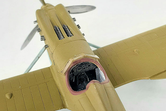 When it
came time to attach the resin upper cowling piece, my example was warped and
short lengthwise. I was able to clamp the piece in place and used a shim to fill
the gap at the gun end. The tail feathers went on without much fuss and just a
bit of filler.
When it
came time to attach the resin upper cowling piece, my example was warped and
short lengthwise. I was able to clamp the piece in place and used a shim to fill
the gap at the gun end. The tail feathers went on without much fuss and just a
bit of filler.
Clean up was required of the wing halves before gluing them together. Due to the poor fit of the wings to fuselage, I opted to attach the ailerons after attaching the wings. There is a slight dihedral to the wings, but the spar stub does not induce it.
There are dimples on the underside of the ailerons for the control wires. The instructions mislabel the ailerons, meaning they call for attaching them to the wrong wing and have the dimples on the top side. The inboard tips have gap big enough to require a shim.
I was dreading attaching the landing gear because four glue points are involved at a single time. The single “V” struts made it fairly easy. The wheel legs made it harder than it needs to be because the end that glues to the wing is square, when it should be beveled. The wheel struts have a forward rake to them, so a gap is left where it attached at the wing. Cyano glue fills it nicely.
Without axles to glue the spatted wheels on, the ball-in-socket join was reinforced with cyano. The tail struts needed a bit of trimming to fall into place.
Liquid mask was daubed in the exhaust ports and some foam padding stuffed into the cockpit and the model was ready for paint.
| COLORS & MARKINGS |
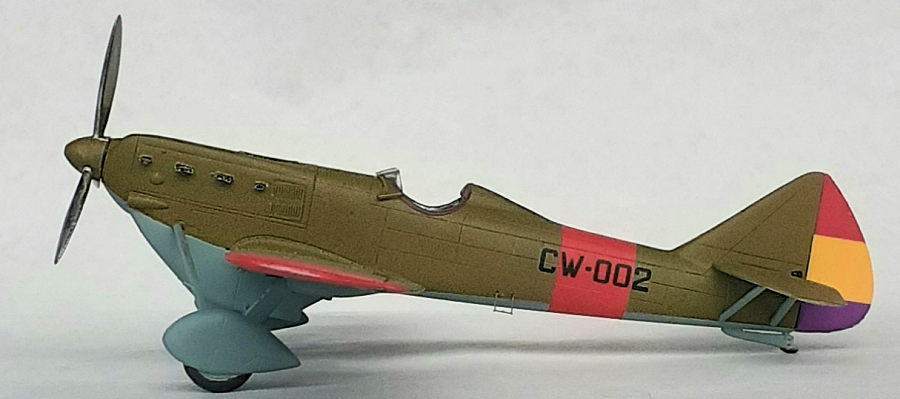
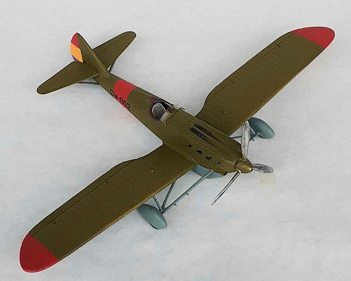
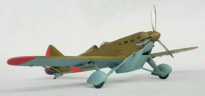
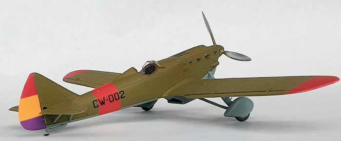 I settled on
a Spanish civil war scheme. That meant it used three colors and four decals. As
a base for acrylic paints, two light coats of rattle can automotive paint primer
were sprayed on then a clear coat brushed on the rudder for its decals. Red was
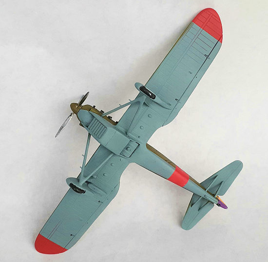
airbrushed on for the fuselage band and wingtips. The red was masked and the
blue underside sprayed. Making the struts was a challenge, but the rest of the
underside was easy. A couple of coats of olive green for the upper surfaces and
a clear coat on the fuselage readied the model for decals.
I settled on
a Spanish civil war scheme. That meant it used three colors and four decals. As
a base for acrylic paints, two light coats of rattle can automotive paint primer
were sprayed on then a clear coat brushed on the rudder for its decals. Red was
airbrushed on for the fuselage band and wingtips. The red was masked and the
blue underside sprayed. Making the struts was a challenge, but the rest of the
underside was easy. A couple of coats of olive green for the upper surfaces and
a clear coat on the fuselage readied the model for decals.
The fuselage decals went on without any fuss. The ruder decals are oversized, so the first one was trimmed and slitted after it dried and Solvaset drenched over the edged so that it would wrap around. When that side dried, the same procedure was don with the other decal, this time cutting “V”s at the color edges so that the colors wouldn’t overlap when it curled to the other side. A coat of flat varnish was sprayed on.
All that was left to add were the machine guns, exhaust stubs, step, wind screen and prop.
| CONCLUSIONS |
This was a trickier build than I expected. There was a lot more trimming was done than on previous Dora Wing kits I’ve built and a lot more internet researching. I spent over 25 hours on this project, which is more than I usually do. That was, however, time well spent. I’m a fan of Dora Wings and look forward to their upcoming Vultee Vengeance and Curtiss AT-9 Jeep releases.
Tamiya has produced a kit in 1/48th scale of the follow-on design 520, so a nice pairing can be done, or perhaps beside Morane-Saulnier MS.230 or a P-26.
20 July 2021
Copyright ModelingMadness.com. All rights reserved. No reproduction in part or in whole without express permission.
If you would like your product reviewed fairly and fairly quickly, please contact the editor or see other details in the Note to Contributors.