| KIT #: | |
| PRICE: | |
| DECALS: | |
| REVIEWER: | Michael Rohde |
| NOTES: |
| HISTORY |
 The MS 230 ,
first flown in February 1929 was a parasol wing design constructed with metal
tubular framing and covered with fabric. Only the forward part of the fuselage
was metal covered. Two cockpits arranged in tandem were accomodated in the
fuselage. The wide fixed landing gear made the aircraft very stable during take
off and landing.
The MS 230 ,
first flown in February 1929 was a parasol wing design constructed with metal
tubular framing and covered with fabric. Only the forward part of the fuselage
was metal covered. Two cockpits arranged in tandem were accomodated in the
fuselage. The wide fixed landing gear made the aircraft very stable during take
off and landing.
Overall the MS 230 was a excellent and stable machine in the air and easy to fly .All military flight training schools in France used the MS 230 as a basic trainer and many examples were exported all over the world. A good number of these aircraft stayed in service as civilian trainers and civilian flight club aircraft for many years after WW 2.
| THE KIT |
This kit contains 105 parts on four frames moulded in grey plastic. Surface detail is done nicely and flash is minimal. One sheet of clear acetate film is provided for the windshields and a set of PE parts.
 Decals are
provided for three options.
Decals are
provided for three options.
MS 230/C23 OK-QHL Brno Medianky Aeroclub 1950
MS 230 ET 2 No 1077 Prague Kybely Aircraft Museum 2012
MS 230 ET 2 No 138 Pilot Captain Amouroux
Advanced Training School Etampes France 1932
Instructions are provided in form of a small booklet containing a parts diagram and a 25 step instruction to assemble the model. Three colour prints with decal and paint scheme options and a colour conversion chart are included.
| CONSTRUCTION |
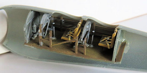
The cockpit build is done according to the instructions in 9 steps and does include some PE parts. These are the seat harnesses and the base of the rudder bars. The assembled cockpit did fit surprisingly well into the fuselage shells. Paints used were wood brown for the cockpit floor. Seat frames in light tan with leather read brown seat cushions, Instrument panels in light grey ,rudder bars and control columns in flat aluminium. Fuselage walls were kept in light grey . Ribs and stringers wood brown.
 Steps 10-
12 deal with the assembly of the exhaust ring, tyres and the air scoop, which
has a fine PE mesh attached to it. The exhaust pipes were opened up with a fine
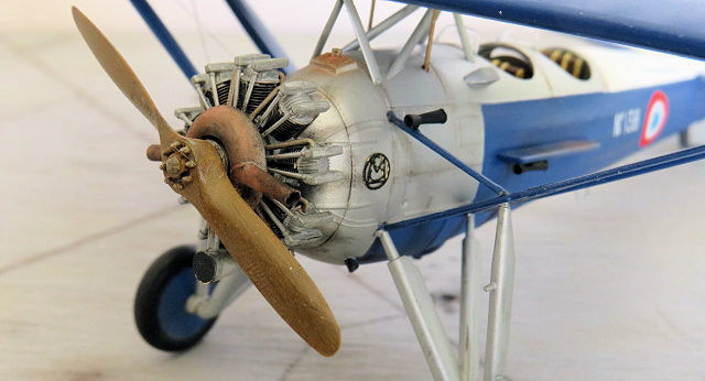
drill. The exhaust ring was painted in flat aluminium, then heavily weathered to
a rust reddish brown appearance using pastels.
Steps 10-
12 deal with the assembly of the exhaust ring, tyres and the air scoop, which
has a fine PE mesh attached to it. The exhaust pipes were opened up with a fine
drill. The exhaust ring was painted in flat aluminium, then heavily weathered to
a rust reddish brown appearance using pastels.
The engine ( steps 13- 16): This was a somewhat fiddly affair. We are dealing with an array of carburettor intake pipes ( 9 of them) and a set of exhaust pipes leading into the exhaust ring ( 10 of these)
I decided to assemble the engine as far as possible and keep only the ignition lead distributor ring (PE) and the pushrod tube ring separate . The reason doing this was to enable me to align the exhaust pipes accurately to the exhaust collector ring. The same applied to the connecting pipes to the carburettor and dry fitting of the engine assembly to the fuselage was necessary. Painting of the individual engine parts and propeller was done afterwards.
Fuselage: (step 17-18 ): The cockpit was glued to the right hand side of the fuselage first and then the other fuselage shell was attached. The rudder and fuselage front cover followed.
 Parasol
Wing: ( step 19-20): The wing comes in two halfes . Elevators are separate.
Cementing the wing shells together I let the glue set and cleaned up the leading
and trailing edges, followed by glueing the elevators into place. Four PE parts
have to be installed . Two of these PE parts have to be bent into shape to align
with the curvature of the wing. The connecting rods for the elevators were glued
into their positions at that time.
Parasol
Wing: ( step 19-20): The wing comes in two halfes . Elevators are separate.
Cementing the wing shells together I let the glue set and cleaned up the leading
and trailing edges, followed by glueing the elevators into place. Four PE parts
have to be installed . Two of these PE parts have to be bent into shape to align
with the curvature of the wing. The connecting rods for the elevators were glued
into their positions at that time.
Tailplane, wing support struts, landing gear legs: ( step 21-25) The horizontal tail plane was on in a jiffy. Rudder linkages ( PE )were glued into place and the holes for the rigging were drilled . This part of the build went smoothly.( to my surprise !) .
The struts attached to the fuselage ( two V shaped and four single ones) were aligned with the attachment points on the wing . I used a compass for alignment by measuring the distance between these points and made sure that the lean in angle was correct. Important!! Drill the holes for the cross section rigging before assembly. See digram in the instructions.
So far so good. Next in line were the struts connecting to the outer wing. Here we have two connecting struts between fuselage and the N shaped part of the main struts which help us to get the angle right. Easy! The landing gear legs went on without any problems either.
| COLORS & MARKINGS |
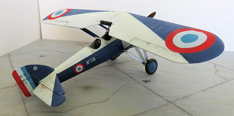
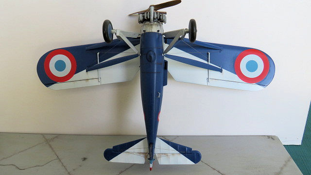
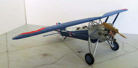 I
liked the white blue scheme best and that is what you can see on the photos.
Masking in this case is easy. No curves, just straight lines. After clear
coating wing and fuselage and drying time complete, I attached small bits
and pieces like the wheels , venturi tubes, the PE MS factory logo and the
wind shields. These I fashioned out of clear plastic . These acetate parts
supplied with the kit are a bit flimsy.
I
liked the white blue scheme best and that is what you can see on the photos.
Masking in this case is easy. No curves, just straight lines. After clear
coating wing and fuselage and drying time complete, I attached small bits
and pieces like the wheels , venturi tubes, the PE MS factory logo and the
wind shields. These I fashioned out of clear plastic . These acetate parts
supplied with the kit are a bit flimsy.
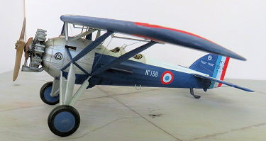
Attaching the wing to the struts was not a problem at all. Alignment was perfect. Last but not least the engine was glued into place as well. Decals went on easy and settled nicely. Weathering was achieved by using pastel colours.
| CONCLUSIONS |
I can say this: Highly recommended. With a bit of care a less experienced modeller will be able to achieve a nice build of this attractive 1930’s parasol wing design.
4 October 2022 Copyright
ModelingMadness.com. All rights reserved. No reproduction in part or in whole
without express permission. If you would like your product reviewed fairly and fairly quickly, please
contact
the editor or see other details in the
Note to
Contributors.