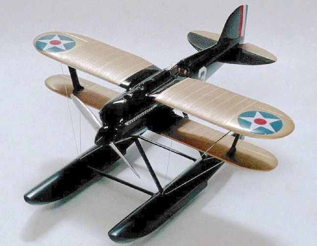
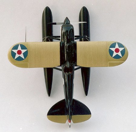
Testors 1/48 Curtiss R3C-2
|
KIT # |
912 |
|
PRICE: |
$5.97 |
|
DECALS: |
One option |
|
REVIEWER: |
Tom Berto |
|
NOTES: |
|
HISTORY |
In the early 1920’s, the Curtiss Aeroplane Company created a series of beautiful, successful race planes that were also “technology demonstrators”. They were flown by the most celebrated American pilots of the era. The most famous aircraft and pilot of that series were the Curtiss R3C-2 1925 Schneider Trophy Winner and its pilot, the incomparable Jimmy Doolittle.
Curtiss got into the post-WWI racing scene at a lean time for the company. Curtiss had the vision to heavily invest not only in high-speed aircraft development, but also more significantly, in high power liquid-cooled engine technology. The technical turning point was the “D-12”, a V-12 engine with no reduction gearing. The success of the D-12, flown in the Curtiss R-6 Pulitzer racers and the 1923 CR-3 Schneider trophy winner, validated a design formula that set the ground rules for all of the significant V-12 engines to follow. These included the Curtiss V-1400 (flown in the R3C-2); the Rolls Royce “R”, Kestrel, Merlin, and Griffon; the Allison V-1710; and the German Daimler Benz and Jumo engines. Those future engines would achieve their performance by the addition and refinement of auxiliary components, such as: robust reduction gearing (allowing higher engine RPM), durable superchargers (to give higher cylinder pressures), high-octane fuels (allowing the higher cylinder pressures without detonation, see: tetra-ethyl lead), better coolants (allowing smaller radiators), and the refinement of sodium-cooled valves.
 The Schneider racers that followed the R3C-2, other
than being monoplanes*, followed the same flush radiator and V-12 formula
of the R3C-2 but did little to improve on it aerodynamically. The R3C-2’s
drag coefficient was .039; the S.6B's was .036. I must note, however, in
deference to R.J. Mitchell and Sir Henry Royce, that the S.6B had over 4X
the power of the R3C-2 and 10% less frontal area.
The Schneider racers that followed the R3C-2, other
than being monoplanes*, followed the same flush radiator and V-12 formula
of the R3C-2 but did little to improve on it aerodynamically. The R3C-2’s
drag coefficient was .039; the S.6B's was .036. I must note, however, in
deference to R.J. Mitchell and Sir Henry Royce, that the S.6B had over 4X
the power of the R3C-2 and 10% less frontal area.
(*The R3C-2 was the last biplane design to win the Schneider. Its predecessor, the R-6, and its landplane configuration, the R3C-1, were the last biplanes to hold the absolute World Air Speed Record.)
Jimmy Doolittle was perhaps the last American military superhero. He combined courage, flying skill, intelligence (he earned a Ph.D. in Aeronautics at MIT in only two years), and a sense of service to his country. His studies toward his doctorate undoubtedly familiarized him with the velocity profiles of turbulent airflow, such as one might encounter while flying the 1925 Schneider course over Chesapeake Bay on a windy day. Doolittle realized that between sea level and 300 feet, there would be a significant difference in the wind speed, as much as 30 mph. Acting on this insight, Doolittle flew the upwind legs as close to the water as possible, but the downwind legs at 300 feet. His experience with this tactic was that he could gain 6-8 mph. He won the race by 33 mph. In fact, Jimmy Doolittle won every race he entered, except the 1931 Thompson when his engine failed.
Doolittle, for all his accomplishments, was a modest, patient, and dedicated man who inspired tremendous loyalty and admiration in everyone who knew him. His R3C-2 (A7054) is preserved in the National Air and Space Museum in Washington DC, wearing its 1925 Schneider race colors.
|
THE KIT |
 I bought the Testors kit because the Curtiss Racers,
in particular the Pulitzer R-6 piloted by Bert Acosta, are some of the
most beautiful aircraft ever flown. The box art also depicted a gold,
orange, blue, and green paint scheme that I thought would add a nice bit
of visual punctuation to my model collection. My first impression upon
opening the box was that it's a no frills kit, only 19 pieces! Yet the
idea of not having to detach, de-flash, paint, and attach 150
pieces of plastic each the size of an ant’s thorax appeals to this
time-challenged father and husband. The big pieces were all the right
shape, and weren’t warped, so I didn’t have to perform major plastic
surgery. I was able to devote my time to refining the kit, not saving it.
I bought the Testors kit because the Curtiss Racers,
in particular the Pulitzer R-6 piloted by Bert Acosta, are some of the
most beautiful aircraft ever flown. The box art also depicted a gold,
orange, blue, and green paint scheme that I thought would add a nice bit
of visual punctuation to my model collection. My first impression upon
opening the box was that it's a no frills kit, only 19 pieces! Yet the
idea of not having to detach, de-flash, paint, and attach 150
pieces of plastic each the size of an ant’s thorax appeals to this
time-challenged father and husband. The big pieces were all the right
shape, and weren’t warped, so I didn’t have to perform major plastic
surgery. I was able to devote my time to refining the kit, not saving it.
|
CONSTRUCTION |
From nose to tail:
The real R3C-2 propeller was forged metal and relatively thin throughout. The kit propeller is molded as one-piece with the spinner and shaped like a wooden propeller, very thick and solid at the root. I carved away as much plastic as I dared at the root on each side, and thinned the rest of the blades. The spinner was too rounded, so I sharpened it up.
The carburetor air inlet is on the top front of the nose. On the model, it resembles nothing so much as a gas cap of an old Chevy pickup. I filed it off and replaced it by cutting in a circular hole at an angle, then gluing a hollowed-out piece of sprue into it.
 I drilled out the molded-in stacks, 12 per side.
This is actually very little work, as the openings are circular and
matched a Dremel ball cutting head diameter exactly. I backed up the
stacks on the inside with strips of plastic pre-painted black, to avoid
see through. Drilling out stacks is close to my favorite part of kit
building, and this kit offered 24!
I drilled out the molded-in stacks, 12 per side.
This is actually very little work, as the openings are circular and
matched a Dremel ball cutting head diameter exactly. I backed up the
stacks on the inside with strips of plastic pre-painted black, to avoid
see through. Drilling out stacks is close to my favorite part of kit
building, and this kit offered 24!
Wings: lots of scraping and sanding is required. First to go were the molded-in insignia. (Thanks for the help, fellas. I’ll take it from here.) Then, off came the heavy rivet detail on the ailerons and the raised lines simulating the breaks between the radiator panels.
The fit of the upper wing to the fuselage was mediocre. The rounded wing leading edge continues right across the fuselage. When this is dropped into the square-edged opening in the fuselage, there is an ugly gap. I filed off the rounded portion of the leading edge where it joins the fuselage, then added upright bits of sheet styrene to the fuselage that I later blended into the wing center section.
On the real aircraft, there is a generous fillet between the underside of the upper wing and the fuselage. I didn't attempt to correct this, but would on a future build.
The lower wing also had some fit problems, which I resolved by scraping away plastic from wing and fuselage to allow a flush fit all around.
The flush wing radiator panels of the real R3C-2
were made from .004” (!) brass sheet. The corrugations are too short and
closely spaced to model in scale, but I came up with an alternate
approach. Everyone who has attempted a bare metal finish knows that the
surface of the plastic has to be more or less perfect, as metallic
finishes show every flaw. I decided to use this to my advantage. First, I
removed all of the raised detail from the wings, then sanded and polished
them smooth. Next, I masked off the center portions and wingtips, leaving
the radiator sections exposed. I cut a small piece of fresh 240 grit
sandpaper, took a deep breath, and drew it, with high pressure, right
over the radiator surfaces of the wings, front to back. I repeated this
until each radiator section was covered with striations running fore and
aft. Finally, I masked off all but the joints between the radiator
sections, the leading and trailing edges of the wing. Using a Paasche Air
Eraser with the “fast” 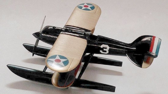 abrasive, I removed the striations from the
unmasked areas. The frosted texture in these areas was markedly different
from that of the striations and the polished wing surface. I used SnJ
Brass Finish with copper polish (hoping to get a bronze-ish look
on the radiators) and SnJ Brass Finish with brass polish on the
smooth wingtips. The results are, to my eye, perfect. The striations and
sandblasted areas are distinct and perfectly convey the sense of
corrugated multi-part radiator panels.
abrasive, I removed the striations from the
unmasked areas. The frosted texture in these areas was markedly different
from that of the striations and the polished wing surface. I used SnJ
Brass Finish with copper polish (hoping to get a bronze-ish look
on the radiators) and SnJ Brass Finish with brass polish on the
smooth wingtips. The results are, to my eye, perfect. The striations and
sandblasted areas are distinct and perfectly convey the sense of
corrugated multi-part radiator panels.
The precursor of the R3C-2, the R2C, had slender interplane struts made from hollowed-out laminated wood. These wings were subject to high-speed flutter, which cost the life of pilot Alex Pearson in September 1924. The interplane struts of the R3C-2 were made from solid laminated wood as a result. In the kit, they are molded with uniform thickness and half-round leading and trailing edges. I filed and sanded them to a thin, aerodynamic profile.
The top wing has a slot that fits over a plug in the fuselage, with the reverse being true of the bottom wing. While looking foolproof, these alignment features didn’t even prove to be fool resistant. Since there was some slop in the lower wing joint, I managed to attach the lower wing with the starboard side rotated about one mm forward. My natural tendency to view the model from above (in which the lower wing was shielded from view) and from the front (where I was checking the alignment) helped preserve my blissful ignorance until the joint was a day old and rock solid. The bright side is that the error is (naturally) hard to see from above and from the front. But, it’s further unnecessary proof that I will continue to do little more than round out the field at IPMS contests.
Cockpit: based on what they provided, Testors must have felt that Doolittle spent the race sitting on a bench seat made from a 2x10, with his hands in his lap! There are no controls or instruments. I felt he deserved a bit better, so I put in a control stick, and scratchbuilt a seat and headrest. I made seat belts with strips of masking tape and buckles with artful blobs of silver paint. I added a tiny instrument panel, brown with black paint circles. Nothing fancy, but a vast improvement over looking into the cockpit and seeing the tab of the lower wing poking up through the slot in the bottom of the fuselage. Given a working stick, Doolittle probably could have flown the plane. (There is a great cockpit photo of the R3C-1 in “The Speed Seekers” listed below.)
 Canopy: the fit was poor. I filed and sanded the
bottoms of the sides and front until it dropped into place in the slot in
the rear of the wing.
Canopy: the fit was poor. I filed and sanded the
bottoms of the sides and front until it dropped into place in the slot in
the rear of the wing.
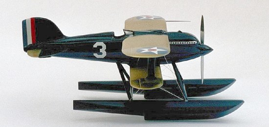
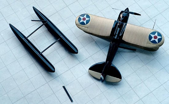
Floats: I securely glued the two sets of halves together, then sharpened the apex of the V’s along the bottoms by flat wet-sanding each side until they came to a point. The floats are large and actually the farthest forward part of the aircraft, so they are the best location for ballast. The model would otherwise rock back onto the rear of the floats, lacking a lump of steel to simulate the D-12 in the nose. I realized this a bit late, so I cut a 1/8” hole in the bottom inside of each float, near but not at the nose, then fed as much .025” tin-lead solder as I possibly could into each float. I had determined ahead of time that I needed at least a yard in each float, and managed to get 44” into the second float. The solder wire would buckle when it hit the far wall, and just feed forward and buckle again when it ran out of room. When the floats just wouldn’t take any more, I flowed in a healthy dose of low-viscosity cyanoacrylate glue through each hole, to lock the maze of solder together. I tapered the edges of each hole, installed tapered plugs fashioned from fat pieces of sprue, and then sanded them flush. The tapered holes and plugs keep the plugs from falling through. It’s a trick handymen use to repair holes in drywall.
After some carving and shaping of the sockets in the floats and the plugs on the ends of the struts, the triangular float struts were installed using the fuselage as a jig. The strut/float joints were then cleaned up, filled, and smoothed. The float assembly then went onto the fuselage with no problems.
The horizontal stabilizers had the raised detail removed, but otherwise no work done. SnJ brass was used on the elevator surfaces, then they were attached to the model.
|
COLORS & MARKINGS |
My reading and surfing revealed that the
polychromatic blue and orange scheme depicted on the box top was for, if
any racer at all, that of George Cuddihy, another pilot of the 1925
Schneider team. The particular aircraft in the very well known
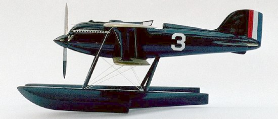 photo of
Doolittle standing on the pontoon of an R3C-2 in September 1925 is not
his plane; it is Cuddihy's. There is another photograph taken on the very
same day of Cuddihy standing on the same pontoon. Doolittle jauntily
hooked his thumbs into his pockets. Cuddihy felt it necessary to hold the
propeller to keep from falling into the water. Doolittle's racer was less
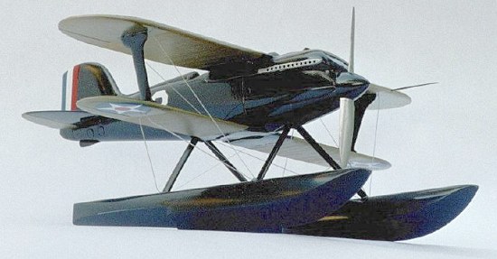
colorful than Cuddihy's: gloss black. But, that was the aircraft I wanted
to recreate, so black the model would be. Although I was at first
disappointed to not be able to use the blue and orange color scheme, I
will say that gloss black is the most forgiving of all aircraft finishes
– the complete opposite of a bare metal finish. My model has some of
both!
photo of
Doolittle standing on the pontoon of an R3C-2 in September 1925 is not
his plane; it is Cuddihy's. There is another photograph taken on the very
same day of Cuddihy standing on the same pontoon. Doolittle jauntily
hooked his thumbs into his pockets. Cuddihy felt it necessary to hold the
propeller to keep from falling into the water. Doolittle's racer was less
colorful than Cuddihy's: gloss black. But, that was the aircraft I wanted
to recreate, so black the model would be. Although I was at first
disappointed to not be able to use the blue and orange color scheme, I
will say that gloss black is the most forgiving of all aircraft finishes
– the complete opposite of a bare metal finish. My model has some of
both!
I masked off the SnJ on the wings and elevators, and airbrushed thinned Testors gloss black onto the model in one pass. It’s hard to hit all of the areas of a biplane fast enough to keep all of the paint wet enough to level. The last thirty seconds of “corrective” spraying did more harm than good and I ended up with some rough finish on the inside surfaces of the floats. That would be hard to polish out, and I made that process even more difficult by continuing on with the decals. These were incomplete (no “3” for the fuselage or “US ARMY” for the tail) and off-color (unless the blue in the stars really was greenish). The tricolor fin flash on the rudder suffered from low density, with variations in the bands, obvious when placed over the black finish. If I were to make this kit again, I would pre-paint the rudder white, then paint the blue and red stripes on. In the opposite order, too – the decals got that backwards. Sigh.
I added the pitot tube on the port wing, using a sorta-stretched sprue that had just the right thickness and taper to it.
Catastrophe!
 I had originally planned to keep this build simple,
but Mr. Van Aken talked me into adding the rigging, which isn't
particularly complex on this aircraft. I also resigned myself to going
back in and fixing the rough finish on the floats, even though access was
going to be difficult. I wanted the gloss paint to set up hard before
proceeding, so I set the model on the mantel behind my woodstove for a
few weeks. Fate intervened. The model got brushed off the mantel and
dropped six feet onto a hard floor. I didn’t witness the catastrophe (no,
a cat didn’t do it), but the model must have landed on the floats. They
parted company with the rest of the model. The hit the lower wings hard
enough to break off both interplane struts. On the bright side, this
neatly solved the problem of accessing the floats for polishing and
rigging! Too bad the crooked lower wing didn’t come off. Miraculously,
neither the hand shaped propeller nor the unique not-so-stretched sprue
pitot tube were damaged.
I had originally planned to keep this build simple,
but Mr. Van Aken talked me into adding the rigging, which isn't
particularly complex on this aircraft. I also resigned myself to going
back in and fixing the rough finish on the floats, even though access was
going to be difficult. I wanted the gloss paint to set up hard before
proceeding, so I set the model on the mantel behind my woodstove for a
few weeks. Fate intervened. The model got brushed off the mantel and
dropped six feet onto a hard floor. I didn’t witness the catastrophe (no,
a cat didn’t do it), but the model must have landed on the floats. They
parted company with the rest of the model. The hit the lower wings hard
enough to break off both interplane struts. On the bright side, this
neatly solved the problem of accessing the floats for polishing and
rigging! Too bad the crooked lower wing didn’t come off. Miraculously,
neither the hand shaped propeller nor the unique not-so-stretched sprue
pitot tube were damaged.
We can rebuild it...
I sanded the rough finish on the floats smooth, then re-shot them with gloss black enamel. With only one set of tops and bottoms to deal with and better access, the paint leveled nicely this time. If I were to build the model again, I would paint the float/strut and fuselage/wings assemblies separately and join them post-paint.
Rebuilding the float-fuselage connection required adding strength to the strut joints, so I drilled out each side of every joint, glued Evergreen rod in the struts, then fitted all back together. I touched up each joint with more gloss black paint.
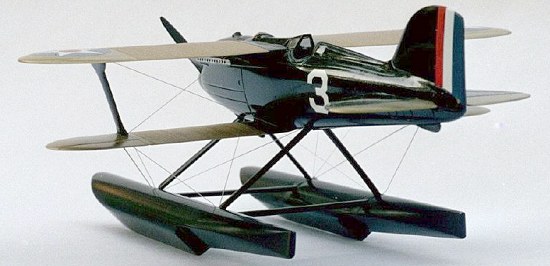
By now, I had located a pair of white "3" decals (from the Hasegawa F4U-4 kit) for the fuselage, so on they went.
 I stretched some sprue and added a piece between a
float and the lower wing. I tightened up the slack holding the model over
a gas-stove burner on a moderate setting and 20 inches up (about eye
level). Unfortunately, as soon as the sprue was tight and I turned the
model to admire it, the float assembly flexed sideways a fraction of an
inch, put more tension on the sprue, and broke it.
I stretched some sprue and added a piece between a
float and the lower wing. I tightened up the slack holding the model over
a gas-stove burner on a moderate setting and 20 inches up (about eye
level). Unfortunately, as soon as the sprue was tight and I turned the
model to admire it, the float assembly flexed sideways a fraction of an
inch, put more tension on the sprue, and broke it.
Hmm. A problem that wouldn't go away. On the real plane, the cables were steel, and stabilized the floats. On the model, the cables are delicate plastic and the floats are actually stabilizing the cables. But the float assembly was too flexible (particularly post repair), so I could confidently predict that every time I tightened a sprue and turned the model the wrong way, the sprue would break. On each side, there are three cables running from the floats to the wings. These would be trouble.
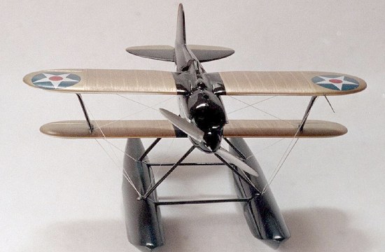
I adopted a new strategy. I installed every piece of stretched sprue needed (14), picking fatter than usual pieces for the float to wing cables. I gave each cable generous slack, then let the kit sit and the joints harden. I did my final touch-ups on the paint, gave the kit a last look-over, and got my photo setup ready. Then, using the stovetop technique, I tightened up every cable simultaneously. That way, any flexing of the floats after tightening was resisted by three cables on each side. The idea worked – they held. To minimize handling between tightening and the photo shoot, I put a piece of paper right on the stovetop and took the pictures there. The multiple pieces of sprue really do share the load – they still haven't broken.
I like stretched sprue. Making it is fun, and its magical way of gradually tightening with heat is my reward for never allowing flame or explosives to touch my models as a kid.
|
CONCLUSIONS |
This kit meets all of my major criteria: decent outline, low part count, and beautiful subject. It doesn't demand that the modeler "do it justice" as a Tamiya masterpiece might. Instead, it says, "Have fun!" I know I did.
|
REFERENCES |
The Speed Seekers, Thomas G. Foxworth, Doubleday and Co. This is a great book about airplane racing in the years 1919-1926. ISBN 0-385-06050-5
June 2004
Copyright ModelingMadness.com.
If you would like your product reviewed fairly and fairly quickly, pleasecontact the editor or see other details in the Note to Contributors.