ESCI 1/48 CF-18A Hornet
| KIT #: | 4012 |
| PRICE: | CAD$25.00 |
| DECALS: | One option |
| REVIEWER: | Pablo Calcaterra |
| NOTES: | Leading Edge 48.87 |
| HISTORY |
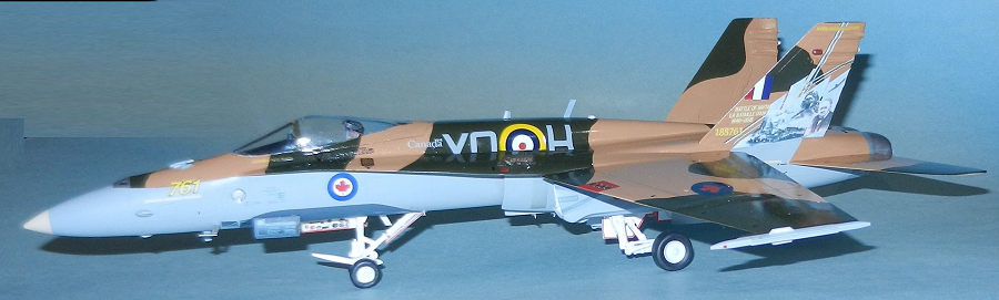
Every year the RCAF Demo team has a CF-18 painted in a particular/representative scheme for that year. A significant milestone in the Air Force or an important Anniversary (i.e. the striking red livery for the 150 years of Canada has been made by Kinetic)
In regard to 188761 it was the airframe to be used by the Demo Team in 2015 to commemorate the 75th anniversary of the Battle of Britain and in 2016 to remember the BTCAP with a very nice scheme with yellow wings and red fuselage.
 This airframe had quite a difficult life. Having been
received on April 10, 1986 while serving in Germany with 439 Sqn it was damaged
during an aborted take off for USAF Alconbury (UK) in October 1987. Capt. D.A.
Friedt ejected, and the plane though it was initially reported as Category A it
was repaired by DASA at Manching and No 1 Air Maintenance Sqn. To execute these
repairs, it is said that the nose of a Spanish F-18 and the wing of an
Australian F-18 were used! In February 1995 the plane was flying with 441 (TF)
Sqn at CFB Cold Lake, Ab. It received ECP avionics update and during a landing
on a wet runway at Yellowknife, NWT in June 2004 the plane ground looped and
again her pilot ejected! One of the missiles came lose and fell from the plane.
She suffered Category D damage.
This airframe had quite a difficult life. Having been
received on April 10, 1986 while serving in Germany with 439 Sqn it was damaged
during an aborted take off for USAF Alconbury (UK) in October 1987. Capt. D.A.
Friedt ejected, and the plane though it was initially reported as Category A it
was repaired by DASA at Manching and No 1 Air Maintenance Sqn. To execute these
repairs, it is said that the nose of a Spanish F-18 and the wing of an
Australian F-18 were used! In February 1995 the plane was flying with 441 (TF)
Sqn at CFB Cold Lake, Ab. It received ECP avionics update and during a landing
on a wet runway at Yellowknife, NWT in June 2004 the plane ground looped and
again her pilot ejected! One of the missiles came lose and fell from the plane.
She suffered Category D damage.
The plane rotated thru several squadrons: 441 in 2006, 409 in 2007. A major overhaul and structural modification took place in 2012. As stated above and due to the low number of hours it was chosen to be the plane of the Demo Team in 2015, 2016.
During the 2015 session it was flown by Captain Denis “Cheech” Beaulieu.
| THE KIT |
This kit represents the very early F-18 tested by the USN Navy in the late 70s. There are many differences between this plane and a CF-188 or CF-18A. It was quite good for what was being flown at the time and represented what was in the air at the time.

There are parts that are very basic (seat, missile rails, tail) with raised panel details (and that are not right), too big air brake and wheel bays with wrong shape. The nose wheels are too large and wide…and the list goes on and on.
Decals are a very small sheet for that plane in test with the USN. Basically there are no stencils. Quite useless with the electroluminescent lights printed in yellow…
My idea was to build a CF-188. When I opened the kit that I had purchased at the local IMPS Show last year I started to find one difference after the other and decided to try to sell it on eBay. Having found many others offering the same kit and with no traction to sell it I changed my mind and using the Revell Monogram kit that I had purchased to convert it to a CF-188 instead of the Esci one I went ahead down the rabbit hole.
| CONSTRUCTION |
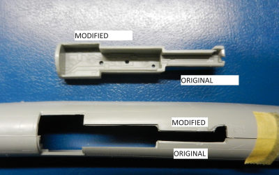
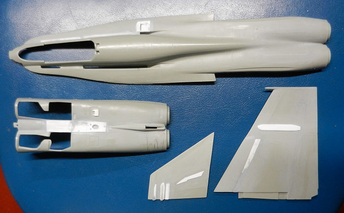
The first task was to correct the main wheel bays. These are the wrong shape and had to be opened up in the fuselage. Because of this the bays themselves had to be modified to match the openings. With pieces of plasticard this was achieved after a lot of work. No wiring/piping was added beyond the basic (and fictitious?) ones supplied in the kit.
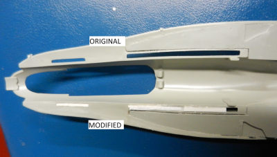
 For the nose wheel bay there is a modification needed
towards the end of it The supports cast in case the plane is represented with
the landing gears closed was removed as well. Because of the new opening on the
fuselage again here I had to rebuild the “box” for the wheels.
For the nose wheel bay there is a modification needed
towards the end of it The supports cast in case the plane is represented with
the landing gears closed was removed as well. Because of the new opening on the
fuselage again here I had to rebuild the “box” for the wheels.
The large spotlight located on the left side of the nose was recreated by drilling a hole and putting a piece of plastic inside the nose. It was then painted in silver and eventually (at one of the later stages) covered with a couple of thick applications of Kristal Klear.
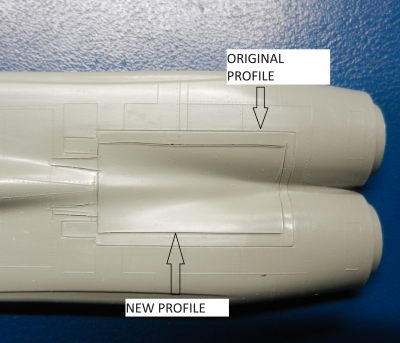
 Then I moved to the top portion of the fuselage. The
kit has the original openings along the fuselage on the LEX. These were blocked
with strips of plasticard and then merged into the extension of the using a lot
of putty sanded again and again after more applications of putty…
Then I moved to the top portion of the fuselage. The
kit has the original openings along the fuselage on the LEX. These were blocked
with strips of plasticard and then merged into the extension of the using a lot
of putty sanded again and again after more applications of putty…
 The air brake is too wide and I rescribed it. While
doing this I found that all the panel lines are wrong and again using the Revell
kit I rescribed them sanding off the original ones.
The air brake is too wide and I rescribed it. While
doing this I found that all the panel lines are wrong and again using the Revell
kit I rescribed them sanding off the original ones.
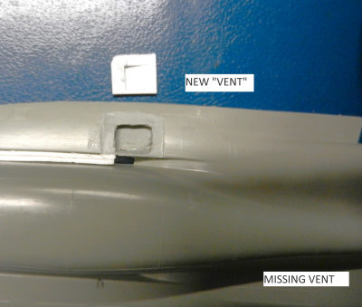 Moving back to the front of the fuselage the openings
present in the LEX fences area are non existent. Thus I cut a couple of square
holes and with thin plasticard constructed the openings. To attached these parts
and make them level with the rest of the surface of the plane I sanded the area
around the openings I had made until the surface was flush. With putty the union
was made smooth. There are several round vents missing in the kit. I used drills
of different sizes to create these.
Moving back to the front of the fuselage the openings
present in the LEX fences area are non existent. Thus I cut a couple of square
holes and with thin plasticard constructed the openings. To attached these parts
and make them level with the rest of the surface of the plane I sanded the area
around the openings I had made until the surface was flush. With putty the union
was made smooth. There are several round vents missing in the kit. I used drills
of different sizes to create these.
 Then it was the turn of the wings and tailplanes.
These don’t have a straight border of attack but it is serrated. I cut out the
narrow border of attack area and reattached it to the wings/tailplanes using a
couple of layers of plasticard to cover the hole between border of attack and
the wings. A lot of putty and sanding plus rescribing panel lines came next.
Then it was the turn of the wings and tailplanes.
These don’t have a straight border of attack but it is serrated. I cut out the
narrow border of attack area and reattached it to the wings/tailplanes using a
couple of layers of plasticard to cover the hole between border of attack and
the wings. A lot of putty and sanding plus rescribing panel lines came next.
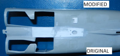 Going back to the undersides of the fuselage I
realized that the kit has a very deep valley between the main landing gear bays
all the way to the engines. Out came again a strip of plasticard that was glued
and several sessions of putty and sanding smoothed the union to the original
plastic. An oval vent present in this area was cut out on the plasticard. The
square intakes on the sides of this vent were scratchbuilt using the Revell kit
as a template. The profile of the area for the arresting hook is wrong: too
flat, curved. I cut out the back part of it and sanded flat the walls.
Going back to the undersides of the fuselage I
realized that the kit has a very deep valley between the main landing gear bays
all the way to the engines. Out came again a strip of plasticard that was glued
and several sessions of putty and sanding smoothed the union to the original
plastic. An oval vent present in this area was cut out on the plasticard. The
square intakes on the sides of this vent were scratchbuilt using the Revell kit
as a template. The profile of the area for the arresting hook is wrong: too
flat, curved. I cut out the back part of it and sanded flat the walls.
The “shoulder” for the folding wings mechanism are not present in the kit. Measuring the Revell ones and using thing plasticard these are added to top and bottom of wings. Under the wings a couple of parts from the spares box were cut and shaped to represent the fairing under the wings where the position lights are located. For the vertical tail planes I again “stole” from Revell the shape of all the sensors and these were recreated using thin plasticard and part of missiles from the spares shaved to shape.
On the nose the gun in the Esci kit is represented with only one hole without the vents/intakes on the side. I created a template with plaster of Paris using the Revell nose. Once I removed the original nose two part epoxy was used to create a better gun/openings. I had to cut out the original gun hole and trim my epoxy part for these two parts to match. It was attached to the fuselage using 2 part epoxy. Once it had dried out I sanded the excess of epoxy and finished the transition using Tamiya putty. The landing gear legs are missing several part/actuators/arms and these were scratchbuilt using parts from the spares and plasticard.
 Then I realized that Esci had not molded the fairings
for the missiles attached to the fuselage. Out came the Revell kit from the box.
I pressed a large blob of blue tac to the Revell fairings and thus had a new
template. It was filled with two part epoxy. When I removed the blue tack I
found the shape quite acceptable but also several air holes in the
surface…Furthermore the internal side of my copies was uneven and did not
conform to the fuselage. I had to sand and scrape the excess until the new parts
and the fuselage were decently matched. With superglue these parts were attached
to the fuselage. Two part epoxy first completed a strong bond. Once the excess
was sanded a lot of putty and sanding merged the union. The wing rails in the
Esci kit are just a round ended rectangle with no structure. With Revell to the
rescue again and using plasticard of different thicknesses I made two new rails.
Then I realized that Esci had not molded the fairings
for the missiles attached to the fuselage. Out came the Revell kit from the box.
I pressed a large blob of blue tac to the Revell fairings and thus had a new
template. It was filled with two part epoxy. When I removed the blue tack I
found the shape quite acceptable but also several air holes in the
surface…Furthermore the internal side of my copies was uneven and did not
conform to the fuselage. I had to sand and scrape the excess until the new parts
and the fuselage were decently matched. With superglue these parts were attached
to the fuselage. Two part epoxy first completed a strong bond. Once the excess
was sanded a lot of putty and sanding merged the union. The wing rails in the
Esci kit are just a round ended rectangle with no structure. With Revell to the
rescue again and using plasticard of different thicknesses I made two new rails.
On the back of the fuselage and close to the exhausts there are a couple of two rectangular screens (2 for the top, 2 for the bottom) that I cut out. The attachment of wing to fuselage is hard to understand. Holes along the fuselage don’t match the tabs on the wings and if forced in the wing is out of angle. I had to cut out the tabs and open the holes on the fuselage to slide them in place.
 Another significant issue is that the spine of the
Esci kit is too wide and rounded. It is nearly impossible to fix unless critical
surgery is performed. I decided to sand the sides as straight as possible and
remove the curvature on the top end. Not perfect but decent.
Another significant issue is that the spine of the
Esci kit is too wide and rounded. It is nearly impossible to fix unless critical
surgery is performed. I decided to sand the sides as straight as possible and
remove the curvature on the top end. Not perfect but decent.
I scratchbuilt the reinforcements located on the inside of the vertical surfaces. These were attached and kept symmetric using a template I crated and tape holding the top of the vertical surfaces in place in a way that they touched the template. The L braces at the fuselage/tails union was were scratchbuilt. Union of tailplanes to fuselage is not good and I had to use more putty to cover the gaps.
After painting the interior details in the cockpit and seat with masking tape harnesses and with the gunsight in place I glued the windshield and canopy to hide the quite simplistic cockpit. I realized that the shape of the clear portion of the back of the canopy is not right so I masked it following the correct contour. Forgot to mention…windshield and canopy had been dipped in Future and left to dry for a couple of days before being attached.
I attached a ventral drop tank support from the spares. A couple of oval bumps in the nose came from some extra pieces in the Revell kit. The arrestor hook supplied by Esci is not good at all. It was much easier to scratch build one using the Revell one as a template.
Nose landing gear wheels are too large and wide. I made a template with blue tac and made copies (1/2 side of the wheels each) using 2 part epoxy then glued together and sanded/puttied. With all those modifications the kit is ready to be painted after covering the cockpit and wheel bays with wet tissue paper.
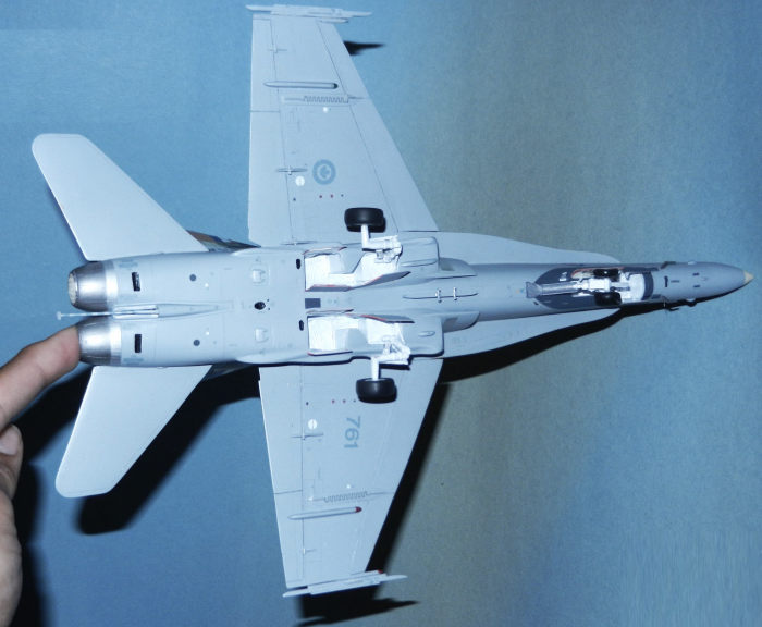
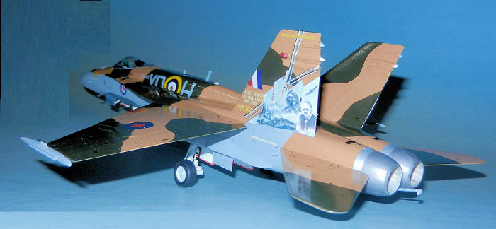
| COLORS & MARKINGS |
The canopy frames were sprayed with black. After a coat with light grey Vallejo Primer the entire plane was painted with ModelMaster FS 36375. The cammo and decals took a lot of time to research on the web. After finding some clear images of the tail planes I masked the grey area where the BoB paintings were to be attached.
I first painted the brown with a combination of FS 30277 Armour Sand and FS 28915 Red Glo in a ratio of 35:30 drops/parts. Once dry and using a template from images from the web I masked the entire plane except the green areas. This were painted with a combination of FS 34079 Dark Green and Black in a 10:1 ratio.
 Once I removed the masks I had to do some little
retouches here and there to some of the demarcation lines. I attached the
landing gear legs and got the plane ready for a session of Future.
Once I removed the masks I had to do some little
retouches here and there to some of the demarcation lines. I attached the
landing gear legs and got the plane ready for a session of Future.
For decals I spent many long days and weeks doing research, printing, testing and adjusting. All undersides decals came from Leading Edge in 1/48.
The top RCAF roundels had actually been painted before applying the cammo. I painted the area in red. For the Maple Leaf I took an image from the web, This one I printed to scale on the same type of paper and then carefully cut it out using a very sharp knife (x-10). I cut a circle in Tamiya masking grid sheet and added to the red area. Then I attached the external side of the circle carfefully matching the circle itself. Then the circle was removed leaving the external “negative” of the circle. Then the tiny Maple Leaf was attached and centered. With the red area protected then I sprayed the blue.
For the unique stencils on the upper sides I scanned the Leading Edge ones (for top surfaces) and converted them to black and printed them in clear decal paper.
The big challenge was the words on the upper side as I don’t have an ALPS printer. My technique is to print the fonts using a background as similar as to the painted surface. In this case I had sprayed the colours on a piece of plasticard. Then I scanned the green and brown and looked for similar hues using Corel Painter. This program would give me around 12 options. I printed all of them in decal paper and once I found one that was close enough I played with the hues/tones till another print on decal paper delivered a matching background colour. This colour was then transferred to PowerPoint where I typed the text(s) to scale.
The roundels on the nose were printed on clear decal paper taking images from the web. I had left a white round area unpainted where the decals (red and blue ink) were appied.
The “761” on each side of the nose were a challenge as it was hard to find images that had a sharp outline. But using some computer features I was able to obtain the desired results.
 One image I found on line is that the internal side
of the main landing gear door was accumulating badges as the year progresses (I
am guessing from other squadrons participating in the same air shows). I printed
these on clear decal paper and attached them to the door.
One image I found on line is that the internal side
of the main landing gear door was accumulating badges as the year progresses (I
am guessing from other squadrons participating in the same air shows). I printed
these on clear decal paper and attached them to the door.
There were some stencils particular to this plane not present in the Flight Decs sheet (for the undersides) and I had to design them. The missing grids on the air intake, behind the LEX fence on the left side and under the nose were printed using images of actual planes. The hinges for the folding wings were designed in PowerPoint, printed and attached.
The fake machine gun ports were created using PowerPoint and printed in white decal paper. Then they were carefully cut out and applied one by one (8 in total). Markings on top of tail and LEX fences were typed, designed and printed using the technique describe several paragraphs above. With the extremely long time consuming process to design, print and apply the decals (they were protected with Micro Mark decal/ink protection) the plane was ready for the final (but not easy) last steps.
| CONSTRUCTION CONTINUES |
A couple of fine coats of Future sealed the decals. At this point I realized that the grey colours (side of fuselage and undersides) were NOT actually shinny like the topsides but matte as in a normal CF-188 in service.
 I had to mask very carefully the demarcation areas
(where some decals are located like the 761s) ensuring that there was no take on
top of them as I did not want to pull them off in a catastrophic accident. Once
the demarcation lines were masked the rest of the top side of the plane was
masked with paper and tape. A nice coat of Model Master matt clear coat was used
for the undersides/sides of fuselage.
I had to mask very carefully the demarcation areas
(where some decals are located like the 761s) ensuring that there was no take on
top of them as I did not want to pull them off in a catastrophic accident. Once
the demarcation lines were masked the rest of the top side of the plane was
masked with paper and tape. A nice coat of Model Master matt clear coat was used
for the undersides/sides of fuselage.
From this moment on everything went fine and fast: starting with the undersides and from the center moving outwards I glued the ventral tank arms on the support (painted in aluminum), wheels and doors, wingtip missile launchers. The antennas and sensors under the nose were added at this point. Main landing gear light was attached to the nose leg and the 3 small lights on the box attached to the same part were painted blue, yellow and red.
The two scratchbuilt red navigation lights were glued to the top of the tails. Then all navigation lights (wingtips, undersides, those close to the LEX fences) were all painted first with silver (as a base) and then clear red and green followed by a few brushed drops of Future.
On the nose area and top of the fuselage several antennas had to be scratchbuilt. The internal side of the exhausts were painted in a creamy colour. The tip of the tail sensors were painted in white. The “bird cutters” were scratchbuilt, attached where the Leading Edge decals are located and then painted in a matching grey.
The lens for the spotlight were made with 2 thick applications of Kristal Klear (with the plane standing on her side!). Once this was dry the plane was ready.
| CONCLUSIONS |
I really like this kind of challenges. Man over plastic. Certainly, there are some areas that are not perfect but it has been a very rewarding project. I don’t think I will ever repeat this experience though…
| REFERENCES |
https://acesflyinghigh.wordpress.com/2015/05/04/planes-of-fame-airshow-2015-rcaf-cf-18-demo-team/
https://photorecon.net/a-behind-the-scenes-look-at-the-2015-rcaf-cf-18-demonstration-team/
https://www.flickr.com/photos/adcristal/18060791590/ and following images in this website.
9 September 2024
Copyright ModelingMadness.com. All rights
reserved. No reproduction in part or in whole without express permission from
the editor. If you would like your product reviewed fairly and fairly quickly, please contact the editor
or see other details in the
Note to
Contributors. Back to the Main Page
Back to the Review
Index Page
Back to the Previews Index Page