Kitty Hawk 1/48 SAAB J.39A/C Gripen
| KIT #: | KH 80117 |
| PRICE: | ~$45.00 |
| DECALS: | Four options |
| REVIEWER: | John Summerford |
| NOTES: |
| HISTORY |
Work on the replacement of the Viggen and Draken aircraft began in 1984. Named the Gripen, (Griffin) it called for the use of the license-built GE-404 engine that also powers the F/A-18 hornet and avionics designed by Ericsson. Stability was sacrificed for maneuverability so a canard and delta wing layout were chosen.
 The first
prototype took to the air on December 9,1988. The usual teething problems
occurred coordinating the new avionics and with airframe. The prototype suffered
a spectacular crash the following February while landing after the sixth test
flight. The control system caused the nose and left-wing tip to strike the
runway. The pilot tried to eject, but pulled the wrong handle. Then the engine
went into after burner. It rolled several times, ingesting gravel, which
(fortunately?) killed the engine. The pilot only suffered minor injuries.
Analysis revealed a lag time between the pilot input and reaction, causing a
repeated input by the pilot.
The first
prototype took to the air on December 9,1988. The usual teething problems
occurred coordinating the new avionics and with airframe. The prototype suffered
a spectacular crash the following February while landing after the sixth test
flight. The control system caused the nose and left-wing tip to strike the
runway. The pilot tried to eject, but pulled the wrong handle. Then the engine
went into after burner. It rolled several times, ingesting gravel, which
(fortunately?) killed the engine. The pilot only suffered minor injuries.
Analysis revealed a lag time between the pilot input and reaction, causing a
repeated input by the pilot.
The next four prototypes were conducting test flights by October 1991.
The Gripen entered service in June, 1993. Control issues appeared again when the first aircraft crashed during a public demonstration the following August. Again, only minor injuries. All Gripens were grounded until the issues were resolved by December.
In September, 1997, the two-seat -B and aerial refueling capable -C variants were in service. The -D variant is an upgraded two-seater. Using the more powerful GE F414G engine, the -NG version also has an upgraded radar and the landing gear relocated into the wings.
The only deployment of Gripens outside of Swedish airspace were reconnaissance missions on behalf of NATO over Libya during 2011.
Gripens have been exported to Brazil, the Czech Republic, Hungary, South Africa, Thailand, and the United Kingdom.
| THE KIT |
 Nine sprues
of light green-gray styrene parts are held in six bags. A separate bag holds a
sprue of 11 clear parts. A photo etch fret and two sheets of decals are at the
bottom of the box. Two of the sprues are devoted to weapons and contain 96 parts
between them. The remaining parts total up to 190. The detail is subtle. Some
minor flash is present and there are ejector pins in unseen places that need to
be dealt with to ensure a good fit.
Nine sprues
of light green-gray styrene parts are held in six bags. A separate bag holds a
sprue of 11 clear parts. A photo etch fret and two sheets of decals are at the
bottom of the box. Two of the sprues are devoted to weapons and contain 96 parts
between them. The remaining parts total up to 190. The detail is subtle. Some
minor flash is present and there are ejector pins in unseen places that need to
be dealt with to ensure a good fit.
Decals are in register and have a flat finish. Markings are included for the weapons plus aircraft from the Swedish, Czech, Hungarian, and South African air forces.
Instructions are printed in a 24-page booklet. The first and last pair are color fold-outs for paint and decals. Two pages are left blank for notes while one page shows a parts map and another page has a load diagram.
| CONSTRUCTION |
Kitty Hawk starts the build with the seat and cockpit tub, but I decided to shake things up a bit and jumped ahead to step 7 and built up the rear fuselage instead. Of note are two inlet pieces at the rear left half that have photo-etch doors. I was unable to find any photos of the aft doors open and only one with the for inlet open. I decided to omit the photo-etch and glued the corresponding pieces in place and put a blanking piece of styrene over the top.
Inserts of interior detail that can be seen if the speed brakes are deployed can be attached, but not needed if the brakes are closed. All of the photos that I viewed show the brakes closed.
 The engine
goes together without any fuss. There are two small stubs that fit into
receptacles inside the fuselage pieces and align the engine properly. While the
liquid cement was curing in one joint, the mating fuselage half was offered up,
and the other stub was aligned. Gluing the halves together proceeded as usual.
The engine
goes together without any fuss. There are two small stubs that fit into
receptacles inside the fuselage pieces and align the engine properly. While the
liquid cement was curing in one joint, the mating fuselage half was offered up,
and the other stub was aligned. Gluing the halves together proceeded as usual.
Building the cockpit held no surprises. I like the single-piece photo-etch harness. It’s very easy to install.
The nose gear well is a separate sub-assembly and fits below the cockpit tub. When it came time to install both units, the tub went in first and the fuselage halves pressed together to ensure proper alignment. When that set, the process was repeated for wheel well and the halves glued together. The instructions call for adding the nose gear at the is time, but it, and the main wheels, can be installed after painting.
If one chooses, the radar can be assembled and installed the nose. There is no hinge mechanism on the nose cone, so I chose to leave it off. The instructions do not indicate if any ballast is needed to prevent tail sitting, so the cone and pitot were left off until later.
Not bothering with the landing gear yet, the main wheel wells were built up and glued inside the lower wing, followed by the upper pieces. The leading and trailing edge control surfaces came next and fit neatly.
Step 14 calls for the wings and rear fuselage to be mated. A test fit revealed a gap at the leading edge. At first thinking perhaps a spreader bar would be needed in the fuselage, a look at next diagram showed that wouldn’t be necessary. Part E7 fits on the underside of rear fuselage forward of the wings. It was taped in place and another test fit with the wings showed the gap closed, so the part was glued in place first.
 While the
glue was curing, attention went back to the cockpit and the canopy was glued in
place after attaching the frame pieces and rear-view mirrors. It was masked to
prevent any damage during the rest of the build.
While the
glue was curing, attention went back to the cockpit and the canopy was glued in
place after attaching the frame pieces and rear-view mirrors. It was masked to
prevent any damage during the rest of the build.
Returning to the wings, they were finally attached to the rear fuselage. The port side was glued first. Making sure of a good seam, pressure was applied to the starboard side for tight fit there. Some minor filling and sanding followed, mostly on the underside.
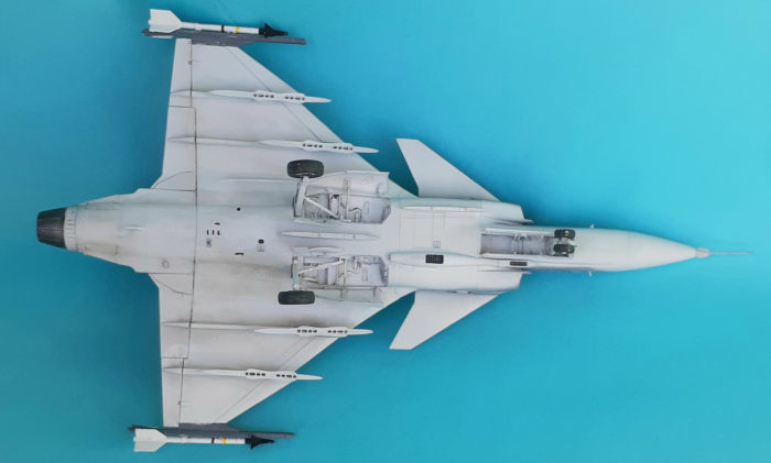
At this point, the instructions have you work from the outside in, meaning add the pylons, then the forward fuselage and intakes. I prefer to work inside out, so the order was: join the fuselage, then the intakes, then the pylons. You have your choice of pylon style, but no indication which ordinance fits to which pylon. After trying for over half-an-hour to figure it out, I took the path of least resistance and chose the pylons illustrated in succeeding steps without ordinance and chose to add only the AIM-9M missiles on the wing tips after painting.
The front and rear portions of the airframe came together. The seam needed a lot of filler to look presentable. This was also the case with the seam for the intakes. A check of the balance confirmed that the model is tail-sitter, so some bits of lead were packed into the nose cone and it was glued in place.
After some debate, the large blade antennae were added and work continued with the model set in a cradle. Of note, blade antenna, part E-21, is illustrated in two different locations in two different steps. It should go into the forward hole shown in step 21not in the rear hole in step 16.
The canards were installed and the model was ready for paint.
| COLORS AND MARKINGS |
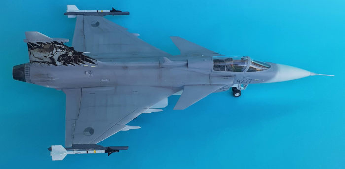
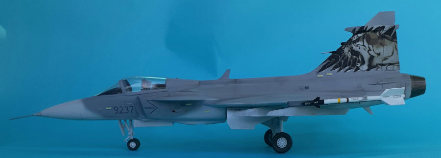
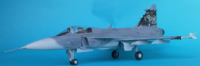
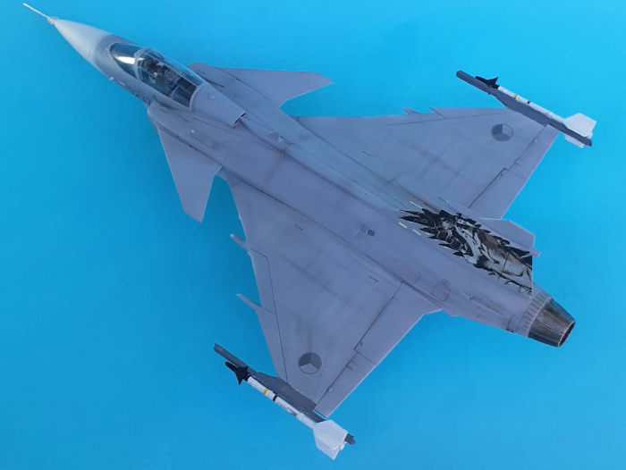
White Mr. Surfacer 1000 primer was sprayed over the entire model. More work was needed on the nose cone before it and the underside were painted Light Gray. The upper surface was painted Medium Sea Gray with a faded overlap on the Light Gray on the sides.
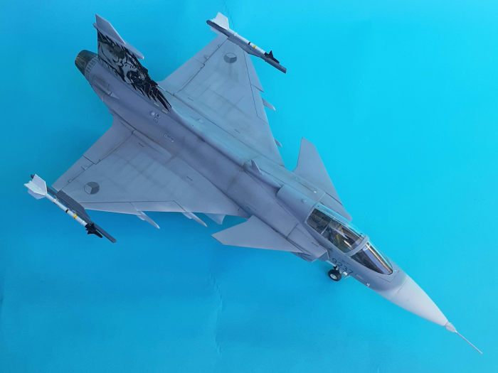
A gloss overcoat from a rattle can prepared the model for decals. I chose the option of the Czech Air Force plane with the tiger motif on the tail. That was the area that needed some SolveASet to get the decal to settle into the nooks and crevices. Getting the decal stripes to wrap around the missile bodies was the most difficult task. SolveASet and prodding with a paint brush got them in place.
Weathering powders were brushed over panel lines and rivets using a stiff bristle brush and a scrubbing motion. An overcoat of clear flat was sprayed over everything.
| FINAL BITS |
I was unable to neatly glue the tiny navigation lights in place, so I substituted blobs of cyano and painted them. A photo-etch antenna was glued to the spine.
 Attention
returned to the main landing gear. The struts and wheels go together well and
the struts mount securely in place. It takes some dexterity with tweezers to get
the retraction arms in place. The doors have positive locating pins and they
glue into place easily.
Attention
returned to the main landing gear. The struts and wheels go together well and
the struts mount securely in place. It takes some dexterity with tweezers to get
the retraction arms in place. The doors have positive locating pins and they
glue into place easily.
Working outward to the wing tips, the AIM-9M missiles and their launcher rails were installed. On one side I glued the rail first and then the missile and on the other side I made the launcher and missile into a subassembly and I found that works better.
The nose gear assembles just as easily as the main gear. With that in place, the tiny angle of attack vanes were glued to the sides of the fuselage and the finishing touch was the pitot glued to the nose.
| CONCLUSIONS |
I think the order of assembly called for makes the build more difficult than it needs to be. That being the biggest gripe, this is a nice kit. The seam between the fore and aft fuselage sections is notable but can be dealt with relatively easily. Some research is required if one wishes to “bomb up” the plane. When completed, one is left with an elegant model that would look good sitting next to a Eurofighter Typhoon model.
John Summerford
10 May 2022
Copyright ModelingMadness.com. All rights reserved. No reproduction in part or in whole without express permission.
If you would like your product reviewed fairly and fairly quickly, please contact the editor or see other details in the Note to Contributors.