| KIT # | 1672 |
| PRICE: | 14 DM ($ 7) |
| DECALS: | FCM 72-02LA |
| REVIEW : | Martin Sczepan |
| NOTES: | PE parts used (Eduard Zoom SS106) |
|
PREFACE |
Sometimes you start a kit as a
‘Slam it together and have fun project’ and it evolves into something
totally different. This was one of these projects. After a pause of almost one
year this was my first model to be built on my new workbench. So I looked for an
easy project and found it in the form of an Academy A-37. I also purchased a PE
set and got a decal sheet for Latin American birds (thanks to Andreas Duda and
Marcus V. T. Borges) and looked forward to have a nice one or two weekend
project.
|
HISTORY & THE KIT |
Since the history of the A-37 and the layout of the kit have already been discussed in Scott's preview, I will start right with the construction.
|
CONSTRUCTION |
This time construction does not start with the cockpit. Since this is a ‘drop-in-affair’, I directly started with gluing the main parts together. At least I wanted to do so. Test fitting revealed the largest shortcoming of this kit. Although the fit promised to be excellent, due to some simplifications in the kit design there were gaping holes in the engine area. Inside of the intake trunk is a gap between fuselage halves and lower wing. The aft end is even worse – no jet pipe is supplied - so the shape is not round and you can look down to the small ‘firewall’ which is near the position of the compressor faces. At least no see trough-effect. One option to solve this problem would be the use of engine covers, another one to mount the FOD screens from the Eduard PE set in the closed and the thrust deflector shields in the deployed position. This would at least partially obscure the view to these problematic areas. I chose the hard way and built jet pipes from ¼” Evergreen plastic tube.
 First the upper and lower wing halves were
glued together. Don’t forget to drill out the mounting holes for the underwing
pylons and aerials if you wish to install them. The gaps in the intake areas
were filled with sheet styrene which was cut and sanded in shape. The intake
area was painted flat black and the PE compressor faces were mounted. The jet
pipe assembly made some modifications on the fuselage halves necessary. I had to
remove some material to get everything to fit. Then it was time to paint the
inside of the pipes in metallic black and to mount the wing on the fuselage. Due
to my modifications the fit was not as good as before, so I had to do some
filling and sanding. The next step was to mount the horizontal stabilizers and
wing tip tanks. At this point I also removed the fin tip antenna and pitot tube
as well as the navigation lights on the tip tanks, since I planned to replace
them with scratchbuilt items.
First the upper and lower wing halves were
glued together. Don’t forget to drill out the mounting holes for the underwing
pylons and aerials if you wish to install them. The gaps in the intake areas
were filled with sheet styrene which was cut and sanded in shape. The intake
area was painted flat black and the PE compressor faces were mounted. The jet
pipe assembly made some modifications on the fuselage halves necessary. I had to
remove some material to get everything to fit. Then it was time to paint the
inside of the pipes in metallic black and to mount the wing on the fuselage. Due
to my modifications the fit was not as good as before, so I had to do some
filling and sanding. The next step was to mount the horizontal stabilizers and
wing tip tanks. At this point I also removed the fin tip antenna and pitot tube
as well as the navigation lights on the tip tanks, since I planned to replace
them with scratchbuilt items.
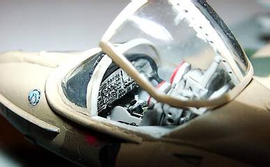
Then it was time to start with
the cockpit construction. Since the opening is large I decided to mount the
seats and control sticks after painting and decaling. The kit lacks the sidewall
padding found on the real aircraft so I simulated this using thin (0.1 mm)
aluminum sheet engraved in the diamond pattern with a sharp needle. To get a
good effect this should be done on a somewhat soft surface (some layers of an
old newspaper). The same technique was used for the seat cushions. After
painting the sidewalls and cockpit tub in different shades of light grey, the
tub was completed with scratchbuilt throttle controls and mounted inside the
fuselage. Since I intended to mount the model on a base, I did not use weights
to keep the nose down. The raised detail on control panel was sanded down and it
was glued with the decking. After painting the assembly in grey and flat black
the painted Eduard instrument panel (PE/film type) was mounted. Everything
seemed to fit nice so I glued the whole instrument panel subassembly to the
fuselage. When I held the windshield in place for a test fit, I realized that
the decking sits much to high so that there is only a very small gap between
decking and windshield. The only way to correct this fault at this stage was to
sand down the decking as far 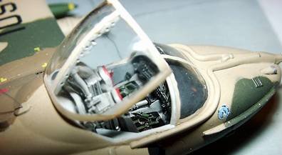 as
possible and to repaint it. The windshield was glued in place and the small gaps
were filled with my favourite fine filler Mr Surfacer 500 from Gunze. Now it was
time to mount all the small parts. I started with the underwing pylons. Next
were the gun fairing and the ducting for the refueling probe. The probe itself
was cut off since the Chilean version of the A-37 uses a short single point
refueling probe instead of the long air-to-air refueling probe found on most
other A-37. For the exact antenna layout you should carefully study your
references since shape and locations of the used antennas can vary. I mounted
all antennas found on Chilean A-37 and modified the shape of the dorsal blade
antenna. The rod antennas right behind the cockpit and on the small stubs on the
leading edges of the horizontal stabilizers were left off at this point.
as
possible and to repaint it. The windshield was glued in place and the small gaps
were filled with my favourite fine filler Mr Surfacer 500 from Gunze. Now it was
time to mount all the small parts. I started with the underwing pylons. Next
were the gun fairing and the ducting for the refueling probe. The probe itself
was cut off since the Chilean version of the A-37 uses a short single point
refueling probe instead of the long air-to-air refueling probe found on most
other A-37. For the exact antenna layout you should carefully study your
references since shape and locations of the used antennas can vary. I mounted
all antennas found on Chilean A-37 and modified the shape of the dorsal blade
antenna. The rod antennas right behind the cockpit and on the small stubs on the
leading edges of the horizontal stabilizers were left off at this point.
|
PAINT & DECALS |
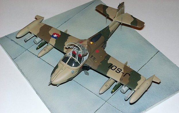
After carefully masking the canopy area with tape and Humbrol Maskol and stuffing the engine intakes and jet pipes with small pieces of Kleenex tissue, the model was primed with a layer of Mr. Surfacer 1000. Then the camo pattern was airbrushed in successive layers of tan (Agama I4M, some Italian sand color lightened with white), earth brown (Humbrol 29, RAF Dark Earth) and dark green (Humbrol 116, FS 34079). Then the landing gear bays were sprayed with zinc chromate yellow (Model Master) and masked with Maskol after drying. The last area to be painted was the underside which was airbrushed with light grey (Humbrol 127, FS 36375). The colors were chosen to match the photo of the plane on FCM’s website. Masking was done with my favorite technique of using Post-It notes paper cut to shape. After some touchups with a paintbrush and hand painting the flat black areas on the intakes and fin the model was prepared for decaling with a layer of Revell clear coat. The decals are a little bit on the thick side but after some treating with Microset and Microsol the went on fairly well. A second gloss coat was airbrushed before the final top coat of Humbrol matt varnish was applied. Weathering was done with a light wash and some paint chipping simulated with silver paint.
|
CONSTRUCTION CONTINUES |
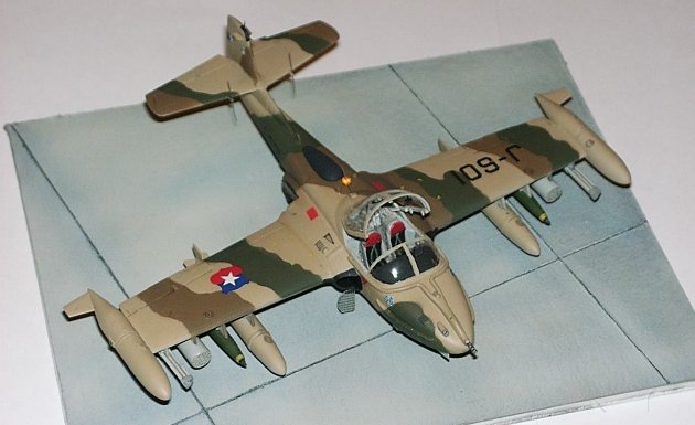
The position lights were made using small drops of clear two-component resin glue painted in transparent red and green respectively. At the final stage all small parts were mounted staring with the landing gear. Unfortunately the kit has some problems here. The scissors were molded on the oleos as solid triangles. I replaced them with scratchbuilt ones from sheet styrene. After mounting of the undercarriage legs and wheels the plane sat with a strange tail up position - obviously the front landing gear is to short. The easiest solution for me was to replace the front landing gear strut with a piece of copper wire of the appropriate length and diameter. The underwing stores were installed next. Since the fins of the Mk 82 bombs were really chunky, I replaced them with scatchbuilt fins from sheet styrene. If you use the SAA-14 dispensers you should mount them in the right direction. The instruction sheet is right here – the openings face to the rear.
Antennas were made from thin aluminum wire, the pitot tube from hypodermic needle with a piece of wire inserted. The FOD screens from the Eduard PE set were mounted in a 'semi deployed' position as they are seen on many reference photos. After all small bits and the ejection seats were installed, the model was mounted on a base. The last step was to glue the canopy in place and do some additional light weathering with pigment dusts. Test fitting of the canopy revealed some fit problems here. The mounting hole for the strut is in the wrong position so the canopy sits in a strange ‘half open’ position. I solved the problem by drilling a new hole in the cockpit tub and somewhat shortening the strut to get the right opening angle here.
|
CONCLUSIONS |
The Academy A-37 is a nice little
kit with good fit and fine details. You get a great variety of underwing stores
to bring your ‘micro A-10’ to life. Only the engine area is a little bit to
simplified for my taste. You should also watch out for the landing gear so that
your model sits on the ground with the right attitude. Everything else is just
nice as it comes out of the box and for the price of the kit you can’t go
wrong.
Highly recommended.
|
REFERENCES |
The A-37 in Action book by
Squadron/Signal
Kiwi Aircraft Images http://www.kiwiaircraftimages.com/aviation.html
FCM decals website http://fcm.cplp.net/fcm-ing.htm
March, 2001
Thanks to Detlef ‘Det’ Hoffmann for the digital photography.
Copyright ModelingMadness.com.
If you would like your product reviewed fairly and fairly quickly, please contact the editor or see other details in
the Note to Contributors.
Back to Reviews Page
Back to Main Page 2019