Kitty Hawk 1/48 MiG-25PD/PDS Foxbat
| KIT #: | KH80119 |
| PRICE: | $74.99 SRP |
| DECALS: | Three options |
| REVIEWER: | Kevin Thompson |
| NOTES: | New tool kit. OOB build with some corrections. |
| HISTORY |
The Mikoyan-Gurevich MiG-25 was designed as a high-speed,
high altitude interceptor as a response to U.S. aircraft that were under
development in the late 1950s. As the Soviet Union continued to improve its air
defense system, it became obvious that the IA-PVO (Soviet Air Defense Force) was
badly in need of a new interceptor to replace the Yakovlev Yak-28 “Flashlight”
and Tupolev Tu-128 “Fiddler” types
that were in service at the time. Priorities were for both higher altitude and
much higher speed capabilies.
In the late 1950s, the Mikoyan-Gurevich design bureau was
testing and developing several experimental interceptor designs, two of which
were built around the new Tumansky R15B-300 engine. At the time, the R15 was in
its infancy, and the turbojet was capable of just over 22,000 pounds of thrust
with afterburner. Mikoyan first produced the Ye-150 prototype, which led to the
later, more refined Ye-152. These two prototypes resembled the MiG-21 in
appearance with their tailed delta configuration, but were much larger, heavier
and faster. Although these single-engine aircraft were prototypes (and
ultimately not destined for production), the research and experience gained with
all facets of flight test were invaluable, and led to more knowledge regarding
high-Mach flight characteristics, propulsion systems, thermodynamics, and
life-support systems.
The Ye-152 was ultimately developed into the Ye-152M
(designated “Ye-166” in its publicized flights for security reasons), and set
world records for altitude and speed in 1961.
By 1960, both the VVS (Soviet Air Force) and the IA-PVO
had issued requirements for an aircraft capable of “about Mach 3” and an
altitude capability of 65,000 feet. The VVS aircraft would perform the aerial
reconnaissance role, with the IA-PVO aircraft serving as an air-defense
interceptor. For the latter, the task of intercepting the potential threat of
U.S. intercontinental bombers such as the Boeing B-52
Stratofortress at long ranges, while
at the same time protecting the vast land area of the Soviet Union was
particularly daunting. The idea was to intercept and destroy the bombers at a
great distance before they reached their intended targets.
Through various forms of espionage, the Soviets were
learning of new high-performance aircraft under development in the United
States, most notably the Lockheed A-12 reconnaissance aircraft and the North
American XB-70 Valkyrie
intercontinental bomber. Both of these U.S. designs were intended for speeds of
Mach 3 and beyond.
 n March 10, 1961, Mikoyan had issued the order to go
ahead with design work on an all-new aircraft, designated Ye-155. Mikoyan
himself was head of the project, with Nikolai Matyuk as chief designer alongside
Rostislav Belyakov (who several years later became Mikoyan’s successor). Mikhail
Gurevich was involved very early on, but soon retired from the MiG firm.
n March 10, 1961, Mikoyan had issued the order to go
ahead with design work on an all-new aircraft, designated Ye-155. Mikoyan
himself was head of the project, with Nikolai Matyuk as chief designer alongside
Rostislav Belyakov (who several years later became Mikoyan’s successor). Mikhail
Gurevich was involved very early on, but soon retired from the MiG firm.
The Ye-155 was a high-wing monoplane with two R15B-300
engines mounted side-by-side in the rear fuselage. Wings were of a low-aspect
trapezoidal layout, with a 42 degree leading-edge sweep. The wings, as well as
the two massive air intake boxes at the front of the main fuselage section,
greatly resembled those on the North American A3J (later A-5/ RA-5)
Vigilante that first flew in 1958.
Outwardly-canted twin vertical stabilizers and ventral fins were fitted, as well
as single-piece, all-flying horizontal stabilizer assemblies.
Construction was of 80% arc-welded nickel-steel alloy, 11%
was aluminum, and 9% titanium in heat-critical areas. The Ye-155 was large, with
a length of over 60 feet, a span just over 40 feet, and an empty weight in the
60,000-pound region. By this time the R15B-300 engine had a thrust close to
25,000-pounds with afterburner.
In April 1962, the CIA-backed Lockheed A-12 made its first
flight from Groom Lake, Nevada, followed up by the USAF YF-12A interceptor
version in August the following year. On March 6th, 1964, the
prototype Ye-155R-1 took to the air for the first time with Alexander Fedotov at
the controls. As flight testing progressed, Fedotov was joined by Pyotr
Ostapenko. These two pilots bore the brunt of all the early flight-testing. The
first several Ye-155 flights were performed by the reconnaissance version
prototype, followed up by the Ye-155P-1 interceptor version in 1965. Early
flight testing did not go smoothly. Many problems of stability, vibration and
fuel consumption had to be solved, particularly as the flight test envelope
speeds gradually increased. It was also found that high-heat paints would be
required, as the 500-plus degree temperatures encountered at high-Mach 2 speeds
would cause the paint to burn and flake off, exposing the bare metal underneath.
Interestingly, the same phenomenon occurred during the XB-70 test program!
As the Ye-155 evaluation program progressed, lessons
learned in flight-test provided for significant improvements implemented on each
subsequent pre-production aircraft. About 200 test-flights had been completed on
both the recon and interceptor versions. Stability had been improved by various
modifications and the flight-performance envelope had been established.
Pre-production examples of both interceptor and reconnaissance types began
rolling off the assembly line at the Gorkii factory near Moscow. The third
reconnaissance aircraft, Ye-155R-3, was now fitted with a full camera suite and
was being evaluated. The interceptor version, with its radome nose designed to
house the Smerch (“whirlwind” or
“tornado”) radar system was in its test phase. The 600-kilowatt radar system was
the most powerful fitted to an aircraft at the time, and was virtually
“jam-proof”. An enormous 5,300-liter (1350-plus gallon), aerodynamic external
fuel tank was developed and mounted in the ventral fuselage to enhance range on
the reconnaissance version.
In early 1965, both the XB-70
Valkyrie and SR-71
Blackbird were now into their
respective flight test programs, although the B-70 was already cancelled as a
bomber, relegating the two prototypes to fly strictly for high-speed research.
At this time, the United States was completely unaware of the Ye-155 program in
the Soviet Union.
This all changed on July 9th, 1967 when a large
military air show took place at Moscow’s Domodedovo airport. Toward the end of
the show, three Ye-155P interceptors and one Ye-155R made a fly-past, with the
air show announcer stating over the PA system; “these aircraft have a capability
of Mach 3”. Once the information had trickled to the west, the United States and
its allies went into a bit of a panic. When the photos of the fly-past and
subsequent information were gathered by U.S. officials, it was believed that the
Soviet Union now possessed a true air superiority fighter, capable of Mach 3,
and probably built almost entirely out of titanium. The NATO ASCC (Air Standards
Coordinating Committee) gave the new aircraft the reporting name “Foxbat”,
and reasoned that the official designation was MiG-23, as this was the first new
design they had seen since the MiG-21 entered service. In reality, the MiG-23
designator was
 assigned to a new, smaller fighter developed from the Ye-231
variable-geometry prototype. With the presumption of the Foxbat’s performance
levels, the U.S. aircraft industry was forced to “up their game” in the
performance requirements of the forthcoming Grumman F-14
Tomcat and McDonnell Douglas F-15
Eagle air superiority fighters under
development. Never before had a Soviet aircraft created such frenzy in the west,
and for a short time the term “Foxbat Shock” was used in the western press.
assigned to a new, smaller fighter developed from the Ye-231
variable-geometry prototype. With the presumption of the Foxbat’s performance
levels, the U.S. aircraft industry was forced to “up their game” in the
performance requirements of the forthcoming Grumman F-14
Tomcat and McDonnell Douglas F-15
Eagle air superiority fighters under
development. Never before had a Soviet aircraft created such frenzy in the west,
and for a short time the term “Foxbat Shock” was used in the western press.
In 1971, the interceptor version of the Ye-155 went into
production as the MiG-25P (“P” standing for
Perekhvatchik, Russian for
interceptor). At roughly the same time, the reconnaissance version went into
service as the MiG-25R (Razvedka is
the Russian word for reconnaissance). That same year, several MiG-25R
reconnaissance flights were made over the Sinai Desert and Israel by Soviet
crews from VVS Detachment 63, which was temporarily based out of Cairo-West air
base, Egypt. The over flights were made between 55,000 and 75,000 feet, and at
speeds between Mach 2.5 and Mach 3.2. The Israeli Air Force, with its Mirage III
and F-4 Phantom fighters, combined with their Hawk surface-to-air missile
system, could do nothing to intercept these fast and high-flying photo planes.
Although the MiG-25 was officially redlined at Mach 2.83, a few flights were
made up to Mach 3.2, but for a very short period, and when these aircraft landed
back at Cairo their engines were damaged beyond repair. The R15B-300 engine was
not able to sustain flight above 2.83 without suffering over-speeding and
subsequent overheating. It was stated that one VVS pilot, named Krasnogorskyi,
had reached 2,125 miles per hour (3400 km/h) on one sortie, and was reprimanded
for his action. Indeed, Israeli radar had “clocked” Foxbats at Mach 3.2 on at
least one occasion. Soviet MiG-25R units operated out of Egypt off-and-on
through 1973.
During the very early 1970s, the Soviet Union claimed
several speed and altitude records with the Ye-155, designated “Ye-266”, again
for international publicity and internal security reasons.
From 1971, the MiG-25P (Foxbat-A) was the main interceptor
for the IA-PVO for several years, and was deployed all over the nation,
including the Far East of the Soviet Union. It was now the backbone of the
IA-PVO. Development of the MiG-25 continued in many subsequent variants,
including bomber, reconnaissance-bomber, two-seat trainer for both interceptor
and recon-bomber versions, and even a “Wild Weasel” air-defense suppressor
version, the MiG-25RBM. Bomb-equipped Foxbats actually performed practice
bomb-runs with reasonable accuracy from over 65,000 feet at Mach 2-plus with
“dumb” free-falling 500kg (1,100 lb) bombs. From that speed and altitude, bombs
would cover several miles in distance to target on free-fall, so a lot of
calculations would have been imperative to achieve accuracy.
On September 6th, 1976 a MiG-25P
surprise-landed at Hakodate International Airport on the island of Hokkaido,
Japan. It was flown by Lt. Viktor Belenko, a pilot with a PVO unit based out of
the Vladivostok region. Belenko subsequently asked for political asylum. This
intelligence coup was not necessarily an impulsive action, but possibly a
carefully-planned exercise to bring a modern Soviet aircraft into US hands,
along with technical manuals for the MiG. Taking technical manuals on flights
was strictly forbidden, so a conspiracy theory makes sense to this day. Belenko
later wrote a book titled “MiG Pilot” which outlines his life in the Soviet
Union prior to the defection, and his surprise of the many ways the west
differed from the east, particularly after Soviet propaganda portrayed the US as
a “poor, rotten society”.
Belenko’s Foxbat was disassembled and analyzed by both US
and Japanese technicians and information of the aircraft’s true potential was
ascertained. Though it was never test-flown by the USAF or JSDAF, they had all
the information they needed, making test-flying unnecessary. After examining the
radar set which used vacuum tubes instead of transistors, and branding the
predominantly steel construction as “crude”, officials in the west had
downgraded the Foxbat’s true potential. The radar used vacuum tubes to ease
maintenance in remote areas, where supply may be limited, and vacuum tubes are
more resistant to electromagnetic pulse (EMP; nuclear) attacks than transistors.
The inspectors cited poor forward visibility and had surmised that in no way the
aircraft is a true dogfighter, with its g-limit at 4.5, and its long-range
missile system of R-40T infra-red and R-40R radar-guided units relegating it
strictly to interception duties. The Mach 2.8 maximum speed was still, in
itself, impressive. The aircraft was returned back to the Soviets dismantled,
via a USAF C-5A and a JSDAF Kawasaki C-1 from Hakodate to Hyakuri where it was
shipped back to the USSR.
 The MiG-25 used an alcohol-based cooling system, as well
as the hydraulic fluid itself was alcohol-based. This makes sense in cold
climates, to protect the fluid from freezing. In Belenko’s book, he mentions the
random alcoholism by MiG-25 ground crews and pilots alike by their occasional
consumption of the fluid as a past-time. The aircraft’s fluid, nicknamed “Massandra”,
was apparently palatable in small doses, but eventually excess took over. This
may have stemmed from long periods of inactivity in desolate locations for these
crewmen. In any case, the MiG-25 was never given an official name, as is the
case with most Soviet aircraft, but its nicknames included “the alcohol carrier”
and “Letayushii
Gastronom” (flying liquor store)!
Eventually, alcohol-based fluids were phased out on later Soviet aircraft...
The MiG-25 used an alcohol-based cooling system, as well
as the hydraulic fluid itself was alcohol-based. This makes sense in cold
climates, to protect the fluid from freezing. In Belenko’s book, he mentions the
random alcoholism by MiG-25 ground crews and pilots alike by their occasional
consumption of the fluid as a past-time. The aircraft’s fluid, nicknamed “Massandra”,
was apparently palatable in small doses, but eventually excess took over. This
may have stemmed from long periods of inactivity in desolate locations for these
crewmen. In any case, the MiG-25 was never given an official name, as is the
case with most Soviet aircraft, but its nicknames included “the alcohol carrier”
and “Letayushii
Gastronom” (flying liquor store)!
Eventually, alcohol-based fluids were phased out on later Soviet aircraft...
Once the Soviets got Belenko’s plane back, they realized
that the US had gleaned all the information they needed from its disassembly and
inspection, and that the Americans had figured out the aircraft’s limitations.
An improved, updated MiG-25 was needed. So less than two months after Belenko’s
defection, a rather hasty plan was put into place in November of 1976 to upgrade
the interceptor version. The upgrades included a new quasi-continuous radar
system, the Sapfir (Sapphire),
recently introduced on the MiG-23 Flogger
variable-geometry fighter. An infra-red search and track (IRST) system was
added, making the weapons system less susceptible to enemy electronic counter
measures (ECM), and allowing sneak attacks on the enemy without having to switch
on the radar. Newer versions of the R-40 missiles had almost twice the range of
the previous versions, and the smaller R-60 close-range or “dogfight” missiles
could now be carried. Provision for the large ventral drop tank was also added.
These
new-production aircraft were designated MiG-25PD (Perekhvatchik
Dorabotannyy: interceptor, upgraded).
NATO identified this new model as Foxbat-E. Production of the new aircraft began
in late-1978, and the earlier MiG-25P models were also subsequently upgraded to
the PD specification (with the exception of the drop tank provision) with the
designation PDS, the “S” meaning “Stroyou”
or field modification. Production ended in 1983, when the Gorkii factory began
building the new MiG-31 Foxhound.
In 1977, a MiG-25 with upgraded engines, designated
MiG-25M, set the absolute world altitude record for a jet aircraft at just over
123,000 feet. It has been said that the aircraft’s engines flamed out just short
of the mark, and the plane coasted on inertia to the record height, slowing down
to just 75 km/h (45 miles per hour) as it reached its zenith.
MiG-25s were exported to Algeria, Bulgaria, India, Iraq,
Lybia and Syria. Today, several examples remain in the inventories of CIS states
after the collapse of the Soviet Union in 1990. Of the export nations, only two
(Iraq and Syria) have used their Foxbats in anger.
Syria had skirmishes with the Israelis in 1981, when they
claimed the downing of an Israeli F-15 with a MiG-25, though this has not been
substantiated.
Iraq claimed several Iranian aircraft destroyed by their
Foxbats during the Iraq-Iran war in the 1980s, including F-4E Phantoms, Northrop
F-5Es, and C-130 transports, among others. It has also been published that on at
least one occasion an Iranian F-14 Tomcat had shot down a MiG-25 during this
eight-year conflict.
On January 17th, 1991, the opening day of
Operation Desert Storm, an Iraqi MiG-25PD piloted by Lt. Zuhair Dawood shot down
a US Navy F/A-18 Hornet piloted by Lt. Cdr Scott Speicher, from the USS
Saratoga. The Hornet was downed by one of the MiG’s two R-40TD infra-red
missiles. It was also reported that in at least one incident four USAF F-15s had
fired a total of 10 air-to-air missiles on two Iraqi MiG-25s, with the Foxbats
having outrun the AAMs!
The first-ever aerial victory for a USAF F-16, and the
first using an AMRAAM missile was the downing of an Iraqi MiG-25 violating the
imposed “no-fly zone” on December 27, 1992.
The last-ever aerial victory for a Foxbat was a USAF MQ-1
Predator drone (UAV) downed by an Iraqi MiG-25PD on December 23, 2002. It was
the first time in history that an aircraft and an unpiloted UAV engaged in
combat. With the launching of “Operation Iraqi Freedom” in 2003, many of Iraq’s
Foxbats were destroyed on the ground, heavily damaged, or later found buried
under sand.
In all, 1,190 MiG-25 variants were produced, mostly interceptors. They were big, fast and powerful, and epitomized Soviet Cold-War technology. The MiG-25 enjoyed a long, reliable service life, with no major defects or bad accidents. Foxbats held a 90% flyable readiness rate, with a mean time between overhauls (MTBF) of 66 hours (the prescribed minimum was eight hours!). It was, along with the Lockheed Blackbird family, and the experimental North American XB-70 Valkyrie, one of only three military aircraft to actually achieve Mach 3, and was the only one built in mass numbers. The MiG-25 was (and is to this day) the world’s fastest operational combat aircraft, and played no small part in deterring U.S. SR-71 reconnaissance flights over various parts of the former Soviet Union where it was deployed in large numbers during the Cold War.
| THE KIT |
As a kid growing up in the 60s and 70s, I had a great
fascination for airplanes, and I started building models when I was seven or
eight years old. My father, Jonathan Thompson, was an aviation and automotive
writer, editor, graphic artist and publisher. Consequently, he had many aviation
periodicals in his possession, both American and foreign. The first time I saw a
picture of the Foxbat, I was absolutely stunned by its sinister good looks. The
aircraft had sharp edges and points everywhere, and the performance estimates I
read of were unbelievable. This thing was a beast! Two other aircraft that
caught 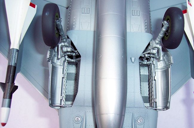 my attention equally back then (you guessed it) were the XB-70 Valkyrie
and Lockheed YF-12A. There were (crude) kits of the two U.S. planes available,
but no “Russian Foxbat” yet.
my attention equally back then (you guessed it) were the XB-70 Valkyrie
and Lockheed YF-12A. There were (crude) kits of the two U.S. planes available,
but no “Russian Foxbat” yet.
The four main issues with this kit were well-covered on
internet forums.
The second issue is the fuselage cross-section just aft of
the main gear. This area should be more rounded down by the main gear; the
cross-section is a bit too slab-sided. This would be very difficult to correct,
but is less noticeable than the forward fuselage shape issue mentioned above,
particularly when the model is completed with armaments mounted. It is still
wrong, though.
The kit’s third major issue concerns the intake doors and
total lack of intake trunking. On the real aircraft, there are upper-mounted
doors in the intakes that are moved during the supersonic flight profile to slow
down intake air. Most, if not all supersonic jets have this feature in one form
or another. In the kit’s instruction sheet, it shows to position the doors fully
down, completely closing off the intakes. Although the later MiG-29 did indeed
have this feature (to prevent FOD entry during taxiing while air was drawn in
through upper louvers), the MiG-25 had no such feature, and closing off the
intakes on this big bird is completely wrong. Fortunately there is a simple
solution for this issue, which I will mention later. The lack of intake trunking
is a bit of a surprise for me, especially considering the price of the kit, but
again, for me, it’s not the end of the world. My finished models are usually
viewed from above while they are sitting on a shelf or table (as are probably
99.9% of everyone else’s). If I was concerned about some IPMS judge with a small
pen light leaning down and looking directly into the intakes for detail, I
suppose I would make up some trunking.
The fourth major issue is the exhaust nozzle assembly. The
two exhaust nozzles on MiG-25 interceptors are very different from the
recon/bomber versions. The former are much more rounded in radial view, and are
much shorter overall longitudinally. The recon and bomber types have larger,
deeper, more fluted nozzles. The kit is supposed to be a PD interceptor, but has
the recon/bomber type nozzles. Probably not quite enough research when the kit
was engineered, but the good news here is that the nozzles are very accurate and
nicely done for the recon/bomber versions.
None of these issues are ‘fatal” (at least not for me),
but there are some out there who literally opted out on purchasing the kit for
those very reasons. Not all kits can be perfect (in fact, not one kit ever was),
but some kits require just a little more modeling skill, and help from the
aftermarket. As of this writing, several resin upgrade and correction sets are
“in the works”, and many initial views appear very well done. The modeler who
wants absolute accuracy can look forward to engines and nozzles, tires/wheels,
some cockpit sets, and possibly corrected nose accessories in the near future.
| CONSTRUCTION |
Following the instruction sheet, here is a step-by-step
description of the build with notes in each segment about where small
improvements can be made, keeping the build “out-of-box”.
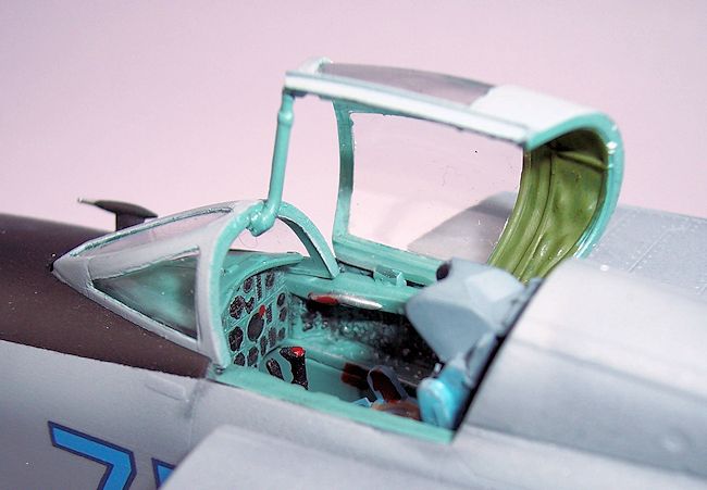
The first two steps are ejection seat and cockpit tub. Not
much to deviate from initially, except the detail is a little on the soft side
and a bit sparse for most. Disregard the “Air Superiority Blue” color call-outs
on the cockpit assembly steps. The majority of the cockpit is the “turquoise”
color used on most Soviet aircraft from the late 1960s onward. Model Master
“Russian Interior Green” is a pretty close match. For the instrument panel, use
photo-etch part “PE3”. It is the one closest to an interceptor instrument panel.
PE4 is appropriate for the forthcoming bomber/recon kits. The KM-1 ejection seat
is a mixture of colors, and good color images can be seen all over the internet
for reference. Again, the cockpit detail is soft and
 sparse; many modelers will
want to use upgrade sets already available for the old Revell kit, or new ones
coming soon.
sparse; many modelers will
want to use upgrade sets already available for the old Revell kit, or new ones
coming soon.
The third step is the nose gear and nose gear bay. Kit
plans say to build up the whole assembly at once, but it would be better to
build up the nose gear bay now, but put the actual gear leg and wheels on later,
after major painting. Gear bay was painted in Model Master Stainless Steel
Buffing Metalizer.
Step four outlines putting nose gear bay and cockpit tub
in place between forward fuselage halves. There was no drama here, and the fit
is just fine.
Fifth step is the intake boxes. First of all, there are
ejector pin recesses in both the intake splitters and the inside walls of the
boxes themselves. Fill and sand these smooth first, then paint the interior
parts of the splitter and boxes in a stainless steel or dull silver. When
installing the intake doors, DISREGARD the instructions on this one. Foxbat does
NOT have fully-closing FOD doors; they are variable ramp doors.
Cement the forward-most intake door pieces F16 and F20 at
the same angle as the plans show, but parts E11 and E12 should be installed
facing towards the engines in a relatively horizontal position, quite well open.
There is even a notch in the splitter and boxes for this second position if one
looks closely. The instructions sheet error probably stems from lack of research
or lack of communication with the “tooling” department. PE parts 1 and 2 are
added now and are a nice touch. Overall shape of intakes is good, but due to
lack of trunking, the doors have a bit of a gap on either side, whereas on the
real aircraft they are a good tight fit, and actually leave slight rub marks on
the splitters from up and down operation.
The end of the fifth step tells you to cement complete
splitter/box assemblies to forward fuselage assembly from step 4. I recommend
installing only the splitters at this time, as getting a good fit between intake
boxes and main fuselage box section later would be a challenge if done as
instructions state. Dry-fitting along the way can let the modeler decide for
themselves regarding this step. On this one I deviated as stated, and was glad I
did later on; it kept sanding to a minimum on a joint that is highly visible on
the finished model.
Steps 6 through 8 are the main gear/wheel assemblies and
main wheel wells. Although the detail is a bit soft, they are well-done overall,
with each main leg comprising some ten plastic parts around a strong metal rod,
with the bends already there, and color-coding in gold or silver for left or
right respectively. I would recommend putting a little more “knee-bend” or
“squat” in the main gear legs, to give the aircraft a more-loaded, tail-low
look. I did not do that on my build, but wished I had. These assemblies can be
built up now and set aside, or done later after main airframe assembly. Tires
are dull black with green wheels/hubs. I like using Model Master FS 34102 for
the green. Gear legs are dull silver. I used Model Master Dark Anadonic Grey
Metalizer for all three gear legs. Detail them with washes or dry-brushing as
you wish. The wheel well box sections go together nicely and have reasonable
detail inside. Leave the main gear leg assemblies out of the main wheel wells
for now, but do test fit them now and open up the holes in the wells now, if
needed. This kit had a very tight leg-to-well fit from not doing that ahead of
time and it was a bit of a challenge to get the model to sit level side-to-side,
so do it now while you can!
Step 9 is the engines/burner cans and nozzles. There are
two minor issues with these assemblies in detail, but until resin aftermarket is
available, they are not really fixable. These include the fan assembly, and
afterburner flame rings. The fans on part D4 are molded going two separate
directions (counter-rotating) where on the real bird both engines rotate in the
identical clockwise direction, so the fan on the left is actually correct. Not a
big issue in the end because you really don’t see them much when assembled.
Because this kit has NO front engine detail, I elected to turn the fans around
facing forward so there was something to see through the intakes. No trunking,
but the fans and vortex generators CAN be seen within the intakes. The flame
rings should actually be dished concave facing forward, but on the kit, parts F1
and F2 are dished convex. Again, a bit more research here during kit engineering
would have made them more accurate. Burner cans D9 through D12 need to be
notched out a bit at the rear, serving as reliefs for all four of the canted
vertical flying surface locater tabs to fit properly once the engines are
sandwiched in the fuselage main box. They have cut-outs on one semi-circular
side of each can, but not the other. This will become obvious to the builder
during dry-fitting. The nozzle ends (the four parts H5 through H8) fit to the
engines is good, but keep in mind that these are correct ONLY FOR A BOMBER OR
RECON VERSION. Kitty Hawk did not provide the correct, shallow, more circular
nozzles for the interceptor version that this kit is supposed to represent.
Aftermarket resin is on its way, but I elected to use the incorrect nozzles to
show exactly how the kit comes. What I did do was cut them a bit shorter, a
 compromise for sure, and still not accurate, but providing a little closer
“interceptor look” to the exhausts. The engine internals were painted in Model
Master Jet Exhaust, with a light tan/grey dusting to give them a slightly
“sooty” look.
compromise for sure, and still not accurate, but providing a little closer
“interceptor look” to the exhausts. The engine internals were painted in Model
Master Jet Exhaust, with a light tan/grey dusting to give them a slightly
“sooty” look.
Step 10 mounts the left and right main gear wells and
engines into the lower fuselage main box. No magic here, except a couple of
notes. Remember to notch out the rear of the burner cans as mentioned in step 9
to make room for the (canted) vertical flying surfaces later, and also to get
the engine assemblies centered in the lower fuselage box. Additionally, the
right side horizontal stabilizer mounting hole may be plugged shut (a production
error) as will be the elevator actuating rod locator hole on the same side.
Opening them up before installing engines will make life easier. Put a strong
bead of cement on the main gear well assemblies where they mate to the fuselage
box. Fit is pretty good, but you will want them to be strong. I used several
beads of cement on them on the inside mating surfaces to make sure the wells
won’t come loose, ever. Inside of fuselage box sections, both upper and lower,
were painted in Model Master Stainless Steel. Due to lack of trunking, the main
gear wells were painted flat black on the inside portion in a compromise to keep
them from standing out so boldly when seen through the intakes.
Step 11 puts the two vortex generator “trees” in the upper
fuselage box section A1. The next step is joining fuselage main box sections A1
and A2 together. Now this exercise really calls for care and patience. The lower
half is warped “fat” and the upper half is warped a bit “skinny”. I carefully
got the locator tabs at the wing root section lined up first, got strong bonds
on them, used clamps and tape, and let them dry. Then I concentrated on getting
the section aft of the wings lined up and carefully cemented and aligned these
edges. Although the box sections are warped individually, as long as the engines
are correctly located and trimmed as recommended, and the two sections are
properly lined up and strongly cemented, subsequent joint-sanding isn’t so bad,
and the box section sights true from any direction when done. Those two warped
parts WILL go together with patience.
Parts
D5 and D7 are intake lower doors. Kit has them posed down, but most photos have
them in the slightly up or “raised” position. Aircraft looks much better with
them closed, but if you want them down or opened, cement them in place as they
are. If you want them up or closed, bend the locator tab on each door
appropriately and then cement them. The latter technique is what was done on
this build. Once the main box is dry and strong, cement forward fuselage/intake
splitters assembly from steps 4 and 5 to front of box section. Pay close
attention to height on both top and bottom here; you will want to get upper
fuselage fairing aft of canopy lined up later. A bit of clamping will pinch the
forward fuselage into the box section correctly, though the joint contact area
is small there. Again, be patient and continue head-on sighting as cement dries.
Left
and right intake boxes can now be fitted as well. Some slight trimming of intake
doors on inboard side may be necessary to have a tight fit against splitter.
Vertical sides of fuselage main box and intakes were a decent fit, but on the
left side upper surface of the intake box (the horizontal area), there was a gap
between it and the splitter. Right side was okay, so I inserted and trimmed a
sliver of .010 sheet styrene, used CA as filler, and problem solved. I was much
more concerned about the side fit of the intake boxes to the main fuselage box,
and was pleasantly surprised with those.
Step 12 hangs the horizontal stabs, ventral fins, wing
root forward aerodynamic fairings, gear doors and ventral forward antenna to the
lower box section. Your modeling style will dictate when you fit these parts
(now or later after painting), but one recommendation is to wait until later to
fit horizontal stabs, because with the engine area at rear of fuselage, the
masking and painting will be greatly simplified with stabs off. Another note is
that main gear doors comprise four doors, two on each side. On real aircraft,
rearmost doors are opened wider than the front ones. The kit provides tabs on
these doors in the correct different angles, and the fit is very good. Main gear
doors have nice internal detail, and the correct aerodynamic blisters on the
outsides, Gear door insides were painted in Model Master Stainless Metalizer.
Step 13 fits the upper air brake door and parachute
fairing to the top of the main fuselage box, as well as the fairing just aft of
the cockpit. The latter is a great fit, and the line from the central upper
fuselage hump lines up well. With regard to the air brake, I recommend cementing
it shut, as the recessed area beneath it in the rear upper fuselage is
ficticious. On the actual aircraft, the air brake fits over smooth sheet metal
beneath it. The detail in the recessed air brake area below it is purely
imaginary. Again, more research into the real bird during kit engineering would
have benefitted the kit.
Step 14 is assembling the wings. Because MiG-25
interceptors have a slightly larger wing than the recon/bomber versions, the kit
provides common upper and lower main wing sections and two different length
tips. The engineering of the interface between these two units is curious; Kitty
Hawk engineered a sort-of “saw tooth” pattern joint to mate them together that
does not exist on the real aircraft, although Eric Chan’s color plates on the
instructions actually show the saw tooth demarcation line! Therefore, once
cement is dry, a significant amount of sanding is required to smooth out this
saw tooth joint, resulting in much fine detail (which was otherwise relatively
accurate) to be lost. So some re-scribing is required. The wingtips are also
thicker than the outer portion of the main wing assembly, so the sanding duty is
a bit intensified. CA glue was used as filler to the joint, and aids in sanding.
The wings themselves look quite nice, with very sharp leading and trailing edges
and a nice, thin airfoil. Separate flaps and ailerons allow the control surfaces
to be posed in various positions, and have a good fit, but the instruction sheet
incorrectly shows both ailerons posed in the down position. This would suggest a
“fly-by-wire” flight control system, which the MiG-25 never had. It is therefore
recommended to pose all wing control surfaces in the neutral position, as this
is the way they appear in the photos that I have seen of
 Foxbats on the ground.
The upper wing fences are molded too long, and intrude into the flap area.
Simply cut and shape them by about 1/8 of an inch or so, resulting in the rear
end of each wing fence stopping just short of the flap hinge line.
Foxbats on the ground.
The upper wing fences are molded too long, and intrude into the flap area.
Simply cut and shape them by about 1/8 of an inch or so, resulting in the rear
end of each wing fence stopping just short of the flap hinge line.
Step 15 fits the vertical stabilizers, missile pylons and
upper by-pass doors to the intake boxes. The vertical stabilizers are nicely
done overall, but in an attempt to cover all variants, Kitty Hawk has molded
some extra detail to the bases of these fins that don’t exist on the PD
interceptor version. Looking at the fins from the side, remove the three tiny
scoops in the very base of each fin side. Then take the RIGHT FIN ONLY, and
remove the horizontal blisters, both inboard and outboard, that are at the very
forward lower part of the fin. The MiG-25PD had these protrusions only on the
left fin, and they do not exist on the right side. Some quick sanding, finishing
off with 400 to 600 grit paper will remove and polish out these blister areas.
Be careful not to break off the delicate antennae on the rear of the fins; they
are nicely done, but fragile. Some re-shaping of the rudder outline will be
necessary for a good fit into each fin assembly, but is not that difficult.
Again, I posed them neutral as well as all the wing control surfaces. I have
never seen any photos of parked Foxbats with control surfaces very far from
neutral positioning. The bulges at the base of fins (parts F17 and F19) are
fitted inboard, and the kit has recesses to accommodate them.
With regards to the upper by-pass doors in the upper rear
portions of the intake boxes, they are a bit sharp-edged with comparison to
photos of the actual plane. Fit is good, but when dry just sand them a little to
round-off the edges. I did not do that on this build, but I should have. Fit of
vertical stabs and wings to fuselage main box is quite good. A small amount of
CA glue can be used to mount them, and then again as filler, and once dry,
finish-sanding really is minimal. These parts all fit pretty well. Remember
during wing assembly that MiG-25 has 5 degrees of anhedral. The right wing is a
nice fit with the correct anhedral, but the left wing will require a small
amount of babysitting and head-on sighting as the cement dries.
The missile pylons can be added now, or later after
painting if you wish. The latter was chosen on this build so I could achieve
some pre-shading with even paint and clear coat applications. Again, your
modeling style will dictate when you wish to install the pylons.
Step 16 is the radar assembly. The radar set in this kit
represents the old “Smerch” radar, and is not accurate for the MiG-25PD, which
used the “Sapfir-25” set. I used none of these parts as I was posing the radome
closed, and not only was it the wrong radar version, but it would not show on
the finished product anyway. However, in this step, I recommend installing
approximately 1.5 ounces (42 grams) to 2 ounces (56 grams) of weight to either
the radome (parts PD3 and PD4), or the very forward fuselage assembly (parts PD1
and PD2). I actually over-killed my nose weight, using 4 ounces (112 grams), and
while the nose gear leg strength may be tested, the model will never be a
“tail-sitter”!
After the radome and very-forward fuselage were installed and cement dried, the complete airframe was seam-sanded. Much to my surprise, the sanding was really not all that heavy. Careful assembly meant the overall parts fit went pretty well. Only a small amount of filler putty was used around the nose/radome area, where I was most aggressive on the sanding to get the shapes a bit closer to correct. The remainder of filling was done using CA glue. Now it was time for painting.
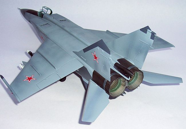
| COLORS & MARKINGS |
The radome and di-electric panels on vertical fins and
ventral fins as well as the forward parts of the wingtip pods were painted in
Model Master Gunship Grey FS 36118. I then masked them off very tightly and
painted the anti-glare panel flat black. After masking that, it was time to use
various metalizers at the aft fuselage and engines. The MiG-25PD (as well as
most variants of the Foxbat) has a large bare-metal area on the fuselage
underside that begins at a panel line just aft of the main landing gear. For
this I used Model Master Dark Anadonic Grey, which closely simulates the bare
steel panels at the bottom of the fuselage at the engine bay. Exhausts and the
metal just forward of them were sprayed in Model Master Exhaust with a light
mist of Model Master Burnt Iron and then polished. In retrospect, a mixture of
the Anadonic Grey and Exhaust may have been a bit more accurate, but photos of
various Foxbats in color have revealed different shades of heated, weathered
engine panels from plane to plane. The Burnt Iron has a bit of a brownish hue to
it. The entire bare metal area was sealed, and masked off.
 For the main airframe color I chose Model master FS 36375
Dark Ghost Grey. I had heard that FS 36230 was also a close match, but to my eye
the former color looked appropriate, especially with a pre-shading of dark grey
or black. The MiG-25 airframes got faded and discolored after a very short
period of time. The same heat effect occurred on the SR-71 Blackbird after
intense heat concentration on high-Mach number flights. The leading edges of the
wings and horizontal stabs were shot with Model Master Aluminum Plate Buffing
Metalizer.
For the main airframe color I chose Model master FS 36375
Dark Ghost Grey. I had heard that FS 36230 was also a close match, but to my eye
the former color looked appropriate, especially with a pre-shading of dark grey
or black. The MiG-25 airframes got faded and discolored after a very short
period of time. The same heat effect occurred on the SR-71 Blackbird after
intense heat concentration on high-Mach number flights. The leading edges of the
wings and horizontal stabs were shot with Model Master Aluminum Plate Buffing
Metalizer.
Once all the paint was dry, the masking tape was removed
and the model was shot with a couple light coats of Testors Glosscote. It was at
this time that I realized another error on this kit; the dark grey di-electric
panels on the ventral fins were too long from the leading edge, they went back
too far. Rather than re-mask and spray them, I let them go, as this was again
what was representative of the kit, this being an out-of-box build.
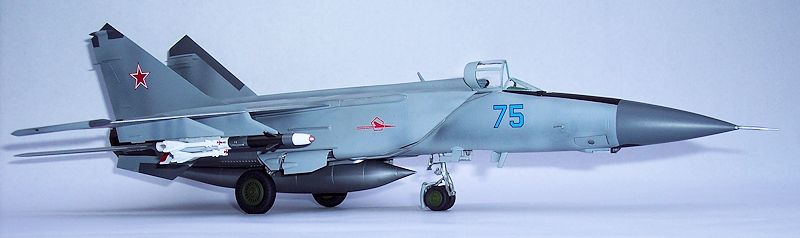
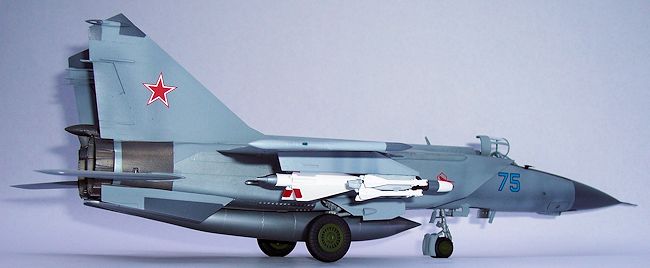
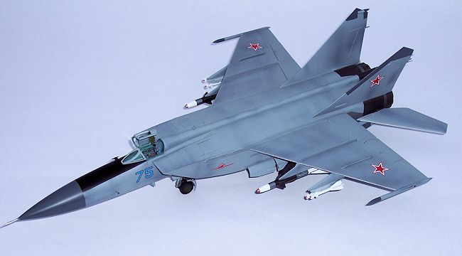
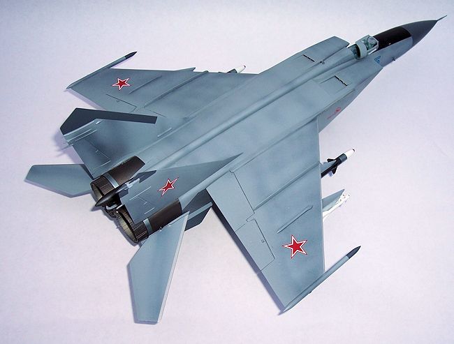
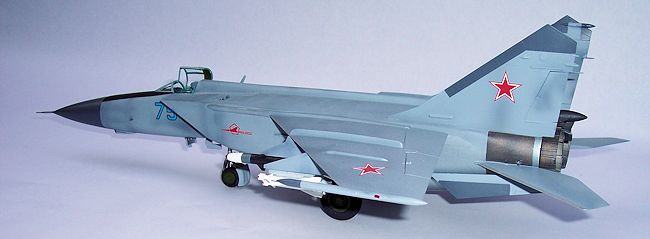
As earlier mentioned, the kit has decal options for Soviet, Ukrainian and Iraqi versions. For me, the only way to do a Foxbat is with red stars on it, so I chose the Soviet option, “Blue 75”, circa 1979. The decals went down nicely with no trouble, and decal setting solution was applied. The kit decal sheet has many stencils on it, but they appear too large and overly-visible when compared to photos of the real thing, so I opted out of the stencil decals, with the exception of the serial numbers for the R-40T missiles. Another coat of Glosscote, then it was sprayed with two thin coats of Dullcote, to tone it down a bit.
| FINAL ASSEMBLY |
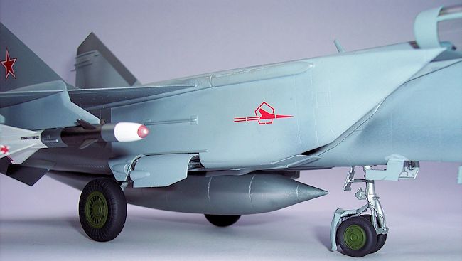
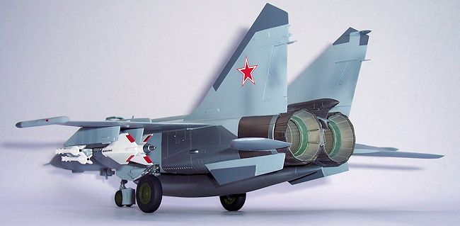
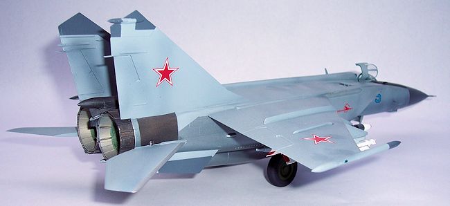
The landing gear legs were installed, followed by he gear doors, then the wheel/ tire assemblies. Doing these in this order assures there is enough room for your fingers to get the main gear doors in place before the wheels and big main tires. Main gear on the Foxbat has slight negative camber, which is built-in to the main gear legs. Another note is that tire tread on Foxbat main gear is raised, although kit used recessed panel lines on the tires. Aftermarket resin is on the way to correct that, as well. Light transparencies were installed just aft of the intakes on the lower fuselage, as was the IRST sensor with black anti-glare panel painted in an elliptical shape. Pitot tube on PD version has no fins on it, like earlier P interceptor or recon versions, so the pitot tube was carefully filled with CA glue, sanded, installed and painted using Stainless Metalizer. Open canopy and fixed windshield were masked, sprayed with Russian Interior Green, then the light grey overall with a Dullcote finish. Inside of canopy just above and behind pilot’s head is a heat-protective area acyually molded inside the canopy. That was painted FS 34102 green, Prop rod for canopy was painted in Russian Interior Green and installed. The prop rod is molded too thick and is clumsy-looking; it could be replaced with stretched sprue on a future build. The missiles were built-up, painted and installed. I used the R-40T missiles inboard and smaller R-60s outboard. The kit is now complete.
| CONCLUSIONS |
 The MiG-25 Foxbat, as an aircraft type, has not been very
widely kitted or particularly well-kitted. Most kits of this iconic Soviet
aircraft were produced in the 1970s or early 80s, without a wealth of
information to gather from with which to make a really accurate model. This
particular kit from Kitty Hawk, despite some inaccuracy issues, captures the
MiG-25 quite well overall. My recommendations to the staff at Kitty Hawk Models
is to study each subject more thoroughly and make the distinction between
variants before issuing a kit of any particular subject, so that the particular
variant is well-defined. However, I do wish to thank Kitty Hawk Models for
producing this kit. It is, despite some inaccuracies, light years ahead of the
kits in the same scale that preceded it, is a subject that few kit manufacturers
have dared to tackle, and is the best kit available, anywhere, of the MiG-25PD
Foxbat-E. I look forward to Kitty Hawk’s future MiG-25 releases, as well as all
the other projects they are currently developing.
The MiG-25 Foxbat, as an aircraft type, has not been very
widely kitted or particularly well-kitted. Most kits of this iconic Soviet
aircraft were produced in the 1970s or early 80s, without a wealth of
information to gather from with which to make a really accurate model. This
particular kit from Kitty Hawk, despite some inaccuracy issues, captures the
MiG-25 quite well overall. My recommendations to the staff at Kitty Hawk Models
is to study each subject more thoroughly and make the distinction between
variants before issuing a kit of any particular subject, so that the particular
variant is well-defined. However, I do wish to thank Kitty Hawk Models for
producing this kit. It is, despite some inaccuracies, light years ahead of the
kits in the same scale that preceded it, is a subject that few kit manufacturers
have dared to tackle, and is the best kit available, anywhere, of the MiG-25PD
Foxbat-E. I look forward to Kitty Hawk’s future MiG-25 releases, as well as all
the other projects they are currently developing.
| REFERENCES |
Various Soviet aircraft-related links on the internet
Special thanks for the review kit to Glen Coleman of Kitty
Hawk Models via Tom Cleaver.
If you would like your product reviewed fairly and fairly quickly, please contact the editor or see other details in the Note to Contributors.