|
BACKGROUND |
For the history of this helicopter and what is in the box please look at Scott’s preview.
|
CONSTRUCTION |
I built this model for two reasons. First was to test my freehand airbrushing technique. The second was to have a model for our local IPMS chapter contest for Russian/Soviet helicopter. I succeeded beyond my wildest imagination with the freehand airbrushing. I did not attend our IPMS meeting, however, as that night we had guests from out of town. Now on to the construction.
 I am not going to bore you with step by step details
of my construction. Instead I am going to point out some of the
construction steps that I think the builder should pay attention to:
I am not going to bore you with step by step details
of my construction. Instead I am going to point out some of the
construction steps that I think the builder should pay attention to:
--The instructions call for painting the instrument panel Russian interior blue-green (actually the mention regular Testors blue but I think they mean Russian interior blue-green). The pictures that I have seen of the instrument panel for this helicopter show a very dark gray color. Therefore, I painted the instrument panel Tamiya acrylic German gray (RLM 66) with black instruments.
--The instructions call for connecting the rotor stubs, the actuator plates and the actuator rods for the rotor to the rotor shaft in the second step and then connecting the whole assembly to the fuselage in the next step. I only connected the bottom most actuator plate (part number). This was done for two reasons: First of all part of the blades are molded on the rotor stubs and need to be sanded to blend in with the rotor blades and painted together with them. This would be very difficult once the rest of the helicopter is assembled. Secondly, the model would go through a lot of handling after this step including getting the paint job. As the actuators are rather fragile, doing so would guarantee that you would break the actuators. Of course the only reason to assemble to rotor shaft at this stage is to have it rotate. However, as the rotors cannot counter-rotate like the real thing this is not very useful or realistic. Therefore, you might as well leave the drive shaft off until the very end and glue it in place. However, I wanted the blades to rotate so I can position them for display. Therefore, I connected the shaft and the bottom actuator plate (as this part cannot be put on the shaft after it is assembled to the locking cap through the base) and connected the assembly through the base to the locking cap. Then the whole thing along with the cockpit was sandwiched to the fuselage halves. By the way, even though the actuator plates are keyed to the shaft, they could be connected upside down. I connected the bottom actuator plate to the shaft upside down and I realized it was upside down too late. Another thing about both actuator plates is that they are attached to the sprues at the stubs for the actuators. It is very easy to cut these stubs off thinking that they are just excess plastic. I did this and I had to rebuild one of the stubs from styrene sheet.
--I don’t know if the molding is bad or I just connected the fuselage halves incorrectly. Whichever the case may be I was left with nasty seam between the fuselage halves that I needed to sand down and in the process lost a lot of detail. I recommend that you take time and even remove the alignment pins for a better fit.
 --The blades are not bent as they would be when the
helicopter is on the ground. After I assembled the blades to the rotor
stubs I gently bent them under hot water until they looked right to my
eyes.
--The blades are not bent as they would be when the
helicopter is on the ground. After I assembled the blades to the rotor
stubs I gently bent them under hot water until they looked right to my
eyes.
--The canopy was very problematic. In my sample if I had attached the canopy’s bottom to the fuselage I would have been left with a huge gap and a nasty step at the joint between the top of the canopy and the fuselage. Therefore, I decided to align the top of the canopy with the fuselage and deal with whatever gap I was left with at the bottom of the canopy. Doing so minimized the gap between the canopy and the fuselage at the top and made the bottom of the canopy flush with the fuselage on the right side. I was left with small gaps in front and to the left side of the canopy. I filled the gap on the top of the canopy with superglue and sanded it flush with the fuselage as best as I could and I filled the gaps at the bottom of the canopy with Kristal Klear. By the way, the windshield wiper that is molded to the canopy is in the wrong position based on the pictures that I have seen. Better modelers my want to scrape the model’s wiper off and scratch-build a new one but that is beyond me. Also I recommend that you paint and mask what I guess are the rearview mirrors on the part that attaches to the top of the canopy before you attach it to the canopy.
--For the camouflaged version the instructions tell you to paint the landing gears and the wheel-wells Russian interior blue-green. However, given that the front wheel well is open and the whole landing gear and the well could be seen even when the landing gears are retracted, I thought it made more sense to paint the landing gear and wheel-wells the underside colors. Therefore, I painted them all Model Master light ghost gray. Although I have not seen close-up pictures of the landing gear of the prototype helicopter that I was modeling, I have seen pictures of other camouflaged Ka-50s where the main landing gear wells are painted the underside color.
--The plates in the middle of the exhaust on my sample were short-shot. This seems to be a trend with Italeri that their thinner parts tend to be short-shot ( I had a similar experience with Italeri’s 1/72 Mig. 29 and its intakes). After assembling the exhausts I filled the gap between the plate halves with superglue and sanded them flush.
 --The instruction tells you to paint only the
connection plates of the rotor stubs bright brass. However, based on
the pictures that I have seen the blade shafts and their blade
attachment plates are bronze colored. Therefore, I hand-painted these
with Humbrol enamel bronze.
--The instruction tells you to paint only the
connection plates of the rotor stubs bright brass. However, based on
the pictures that I have seen the blade shafts and their blade
attachment plates are bronze colored. Therefore, I hand-painted these
with Humbrol enamel bronze.
--Even though the tail wing is connected to the fuselage at panel lines, the gap between it and the fuselage maybe to deep for your liking. You may want to fill this gap either partially or completely to tone down this effect.
--The AT-9 missile racks should be connected to the pylon before attaching the missiles as that way the front rack and the rear rack could be aligned together.
--The instructions for painting the AT-9 missiles are not very clears as they do not tell you what color to paint the hatches on the missile tubes. Internet was no help on this either as every picture of AT-9 that I have seen seems to have its own color scheme. Therefore I decided to paint the front portion of these missiles flat black and their rear portion field brown (FS 30117) following more or less the instructions.
--There are small handles on and next to the hatch on top of the fuselage as well as a stub antenna for the bottom of the fuselage. I attached these to the fuselage before painting in the hope that I won’t knock these off as I prefer to use plastic cement whenever I can. If I had waited until the model was painted then I had to attach them with superglue. It suffices to say that I knock off the handles and I lost them and I broke off the antenna. I had to make new handle from thin lacquered wire and connect them along with the antenna to the fuselage with superglue after the painting was done.
--The area around the turbine intakes is painted black. However, masking these areas is extremely difficult once the intakes are attached to the fuselage. After brush painting the turbine faces and the struts for the intake shields silver and masking them, I shot these parts black and masked the areas that are to remain black with liquid mask. I then attached these to the fuselage.
|
COLORS & MARKINGS |
 Before I get into the details of painting I think I
should mention that I had dipped the canopy in Future and had masked it
with Bare Metal Foil before attaching it to the fuselage. Furthermore, as
the door to the cockpit is separate from the main canopy and I did not
want to get any paint into the cockpit, I stuffed the cockpit with wet
tissue paper and then attached the door to the canopy with Model Master
Clear glue after the door was masked with Bare Metal Foil too. I had
stuffed wet tissue paper into the rotor shaft well and masked the shaft
with Parafilm-M. I then painted the windshield wiper black and shot the
whole canopy area with Russian interior blue-green so that from the
inside the canopy framing would have the same color as the cockpit
interior.
Before I get into the details of painting I think I
should mention that I had dipped the canopy in Future and had masked it
with Bare Metal Foil before attaching it to the fuselage. Furthermore, as
the door to the cockpit is separate from the main canopy and I did not
want to get any paint into the cockpit, I stuffed the cockpit with wet
tissue paper and then attached the door to the canopy with Model Master
Clear glue after the door was masked with Bare Metal Foil too. I had
stuffed wet tissue paper into the rotor shaft well and masked the shaft
with Parafilm-M. I then painted the windshield wiper black and shot the
whole canopy area with Russian interior blue-green so that from the
inside the canopy framing would have the same color as the cockpit
interior.
This project was picked primarily for testing my free-hand airbrushing skills. After airbrushing the gun bay and a couple of grills on the fuselage flat black and masking them, I airbrushed the underside and the wheel-wells along with the wing pylons with Model Master light ghost gray. I then masked the wheel-wells with liquid mask and masked the underside with Tamiya tape. I then shot the model with Model Master Sand according to the instructions. Next I tried to paint the green parts of the pattern with Model Master field green free-hand with my Badger 155 double action airbrush and I made a mess of it. Ben Pada of our IPMS chapter had told me to use very thin paint with a single action airbrush and adjust the paint knob to just a trickle so I could have a very fine line. Ben also told me to have all the colors of the camouflage ready to touch up as I progress with my painting. I also asked for advice on the Modeling Madness forum with regards to this and Lee Kolosna also offered similar advice with the addition that I should first shoot the whole model with the lightest color of the camouflage then draw the camouflage pattern on this base color with pencil and finally try to paint inside the lines (like I did when I was in grade-school).
 Armed with this knowledge, I shot my model with
Model Master sand again using my Badger double action and got rid of the
green areas that I had messed up. After the sand was dried I drew the
camouflage patterns on it and proceeded to paint inside the lines with
field green. As much as I tried I could not get the thin lines that I
needed with my Badger airbrush so I dug up my old Aztek 1000s (now sold
as a Testors single action airbrush) with a medium head. I thinned my
paint to a mixture of 30% paint and 70% thinner and turned up the
pressure on my compressor to maximum so I could get lines about a
millimeter or so thick. I then proceeded to paint inside the lines and
was surprised at how well this technique worked. It was a tedious process
and altogether took about six hours as I had to use each color at least
four times for touch-ups and pattern refinement. However, in my opinion,
the end results was well worth it as I never thought that I could come up
with such a realistic feathering in 1/72 scale free-hand. I should note
the previously I had used soft masks to get my feathering but given the
complexity of the camouflage pattern and the shape of the model it is
doubtful that I could have achieved as fine a pattern with soft masks as
I did freehand. I also painted the top edge of the pylons appropriate
camouflage colors (three of them green and one of them sand).
Armed with this knowledge, I shot my model with
Model Master sand again using my Badger double action and got rid of the
green areas that I had messed up. After the sand was dried I drew the
camouflage patterns on it and proceeded to paint inside the lines with
field green. As much as I tried I could not get the thin lines that I
needed with my Badger airbrush so I dug up my old Aztek 1000s (now sold
as a Testors single action airbrush) with a medium head. I thinned my
paint to a mixture of 30% paint and 70% thinner and turned up the
pressure on my compressor to maximum so I could get lines about a
millimeter or so thick. I then proceeded to paint inside the lines and
was surprised at how well this technique worked. It was a tedious process
and altogether took about six hours as I had to use each color at least
four times for touch-ups and pattern refinement. However, in my opinion,
the end results was well worth it as I never thought that I could come up
with such a realistic feathering in 1/72 scale free-hand. I should note
the previously I had used soft masks to get my feathering but given the
complexity of the camouflage pattern and the shape of the model it is
doubtful that I could have achieved as fine a pattern with soft masks as
I did freehand. I also painted the top edge of the pylons appropriate
camouflage colors (three of them green and one of them sand).
After the painting was done I removed the masks on the fuselage with the exception of the canopy I shot the model with Future and let it dry for about two hours. I then applied the decals. Italeri decals were thin and in register and reacted reasonably well to Micro Set. After the decals were dry I wipe the model with a damp tissue to get rid of the excess glue. I then airbrushed the whole model with Micro Flat finish. I had previously used Acryl flat coat but the last couple of times that I had used it the finish had cracked. As I did not want to use lacquer top coats again I am now using Micro Flat finish. This was the second time that I had used this and I am quite happy with it. As this was a prototype helicopter I did not do any weathering on it.
|
FINAL CONSTRUCTION |
After I was done with painting and decaling the fuselage I removed the masks on the canopy and removed the tissue from inside the cockpit. Unfortunately I was left with the residue of the glue from the Bare Metal Foil. I tried to clean this up with alcohol but I managed to fog up the canopy and some of the finish around it. This meant that I had to do a little bit of touch up of the canopy framing and to coat the canopy with a little bit of Future. I am not sure what it is but even though the windows were brushed again with Future, I am seeing a little bit of fogginess even though their surfaces seem very smooth and shiny. By the way, after I was done with this model I read in FSM that Goo Gone seems to work on Bare Metal Foil glue rather well and next time I plan to use it.
Next I attached the gun and the exhausts with superglue. Both these items were painted with Metalizer non-buffing gunmetal. I also painted the inside of the exhausts flat black. I wish I had a better picture of the gun bay as I would have loved to spruce up the gun with a couple of hydraulic lines. I also attached the turbine intake shields.
 After the exhausts and the gun were attached I
connected the landing gears. As the wheels for the main landing gear are
visible from outside when the landing gears are retracted and they are
supposed to be painted green, I painted them Model Master field green to
match the green of the camouflage even though the instructions said that
I should paint them a different shade of green. The pictures that I have
seen of this helicopter are inconclusive about the color of the wheels
and to my eyes they seem to match the green color of the camouflage. I
had a little bit of trouble getting the landing gears to fit properly and
had to enlarge their attachment holes on the fuselage in order to get
them to fit. Because I had not enlarged one of these holes enough as I
was forcing the landing gear in the hole I broke it and had to fix it
with superglue and paint it again. I should mention that the landing
gears seem very well done with fine details. Also I had to thin the front
right attachment point of the front landing gear a little to get it to
fit.
After the exhausts and the gun were attached I
connected the landing gears. As the wheels for the main landing gear are
visible from outside when the landing gears are retracted and they are
supposed to be painted green, I painted them Model Master field green to
match the green of the camouflage even though the instructions said that
I should paint them a different shade of green. The pictures that I have
seen of this helicopter are inconclusive about the color of the wheels
and to my eyes they seem to match the green color of the camouflage. I
had a little bit of trouble getting the landing gears to fit properly and
had to enlarge their attachment holes on the fuselage in order to get
them to fit. Because I had not enlarged one of these holes enough as I
was forcing the landing gear in the hole I broke it and had to fix it
with superglue and paint it again. I should mention that the landing
gears seem very well done with fine details. Also I had to thin the front
right attachment point of the front landing gear a little to get it to
fit.
After the landing gears were attached I moved on to the under-wing stores. I had already made the rocket pods and had painted them with Gunze lacquer aluminum polishing metalizer and had polished them to a shine. I then attached them to their pylon with superglue. I also attached the AT-9 missiles to their racks, carefully aligning them as there is not positive lock. I think either the racks are too thin or the pylons are too long as the pylon does not allow you to attach the middle two missiles on the bottom to their attachment points on the racks properly. After the missiles and the pods were attached to their pylons the pylons were connected to the weapons’ wings with superglue.
Finally, I attached the rotor blades, the top actuator plate and the actuators. As I mentioned before I had attached the bottom actuator plate incorrectly and this was when I noticed it. I had to fudge a little bit here and connected the actuators that connect the bottom actuator plate to the bottom rotor on the wrong side of the blades. The rotors and the actuators were painted the proper colors before attachment according to the instructions with the exception of the connecting rods as mentioned before. I should also mention that it would be easier if you connected the bottom rotor first, then the actuators that connect it to the bottom actuating plate then the top actuating plate and the actuators that connect it to the bottom actuating plate and finally the top rotor and the actuators that connect it to the top actuating plate. I did not do so and had to be very careful as I attached the actuators with superglue to the rotors.
|
CONCLUSIONS |
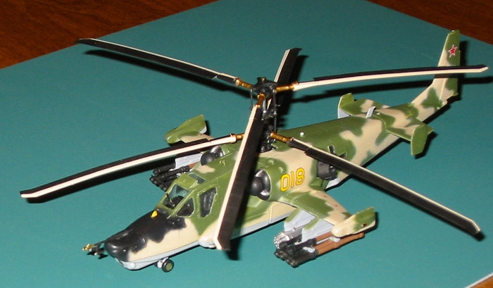
While this was not a well-built model and the model itself had many short-comings in terms of fit I am very please with the results as this model sports the best paint job I have ever put on a model and the subject is rather interesting and looks menacing with all its missiles and rockets. Overall grade: B.
August 2004
|
REFERENCES |
http://www.military.cz/russia/air/helicopters/Ka_50/ka50_en.htm