|
KIT: |
Revell 1/48 A-10A Thunderbolt |
|
KIT # |
4503 |
|
PRICE: |
$5.00 (1979) |
|
DECALS: |
One aircraft |
|
REVIEW: |
Roger Jackson |
|
NOTES: |
|
|
HISTORY |
Fairchild’s A-10 Thunderbolt II was the direct result of the Department of Defense’s cancellation of the Army’s fledgling purpose-designed AH-56 Cheyenne attack helicopter program. Lobbying hard to support its parochial interests during the Vietnam War era of increased defense spending, the Air Force simply would not cede the close air support (CAS) mission to the Army, though the inherent dangers were detested as they placed costly aircraft and expensively-trained pilots at risk.
Citing the notorious Key West Accords of 1948, whereby the Army was forbidden under the terms of this pact from arming helicopters for offensive missions or operating any fixed-wing aircraft other than utility/liaison/spotter types, the Air Force claimed dominion over the Army in this regard. The Navy and Marine Corps, in an admirable display of defiance, had stormed out of the Key West meetings, leaving the Army to futilely flail Don Quixote-style, against the Air Force windmill.
The Vietnam War, and the Army-developed tactics and doctrine used to fight it had de facto abrogated the Key West Accords, though the Air Force obstinately refused to acknowledge it. Helicopter gunships, combined with air-mobile infantry, armored cavalry, and fixed firebase artillery support, had proven the efficacy of the combined-arms operational concept. Bell Cobra attack helicopters gave field commanders instant and accurate fire support, of which the same could not always be said for Air Force tactical aircraft.
Jets were too fast and generally too vulnerable to small-arms fire to be truly effective tools in this arena, while organic helicopter assets were able to provide precise fire support in surgical fashion to local theater commanders at all levels from squad to division, and on demand. This gave the Army the flexibility to adapt to rapidly changing battlefield conditions and make maximum use of fire-and-maneuver opportunities as they arose. Helicopter gunships became a staple in the Army’s combined-arms battle doctrine and would remain so.
 Lockheed’s Cheyenne was
a second-generation gunship platform embodying much of what was learned with
Bell’s AH-1 series. As a result, it was faster, carried a heavier payload, had
advanced survivability features, and offered a complete suite of
state-of-the-art sensors to give it night/all-weather capability. While it was
considered revolutionary by contemporary standards and most certainly would have
advanced Army Aviation to the cutting edge, it was also very expensive at about
$2,000,000 a copy.
Lockheed’s Cheyenne was
a second-generation gunship platform embodying much of what was learned with
Bell’s AH-1 series. As a result, it was faster, carried a heavier payload, had
advanced survivability features, and offered a complete suite of
state-of-the-art sensors to give it night/all-weather capability. While it was
considered revolutionary by contemporary standards and most certainly would have
advanced Army Aviation to the cutting edge, it was also very expensive at about
$2,000,000 a copy.
The Air Force, with more than casual interest, watched the Cheyenne flight-test program progress to near-production status, then began to squawk and snivel to Congress and the Department of Defense, shamelessly using surrogates in the aerospace industry. Congress, with various alleged payola and bribery scandals involving Lockheed’s overseas marketing practices still simmering, was loath to listen to any Lockheed or Army rebuttals, and after review upon review, ultimately killed the promising AH-56.
With the Army’s legitimate (and crucial) need for a close-air-support aircraft yet unfulfilled, the Air Force (still stubbornly standing obstreperously on the ludicrous Key West Accords) stepped in and offered to purchase a new aircraft specifically designed for the mission if only they could get their hands on all that Army-allocated money. To extinguish inter-service pyrotechnics, the Air Force condescendingly agreed to allow Army planners to "assist" in delineating the program’s parameters, though there was never any doubt as to who was actually driving the train.
Congress acquiesced and the Air Force issued a request-for-proposal to the aerospace industry. The specifications mandated a pair of high-bypass turbofan engines, a 12,000 lb payload, extended loiter time, and curiously enough, VFR avionics only. Wisely, battle damage resistance was stressed, while over-engineered high-tech features were discouraged. Several companies expressed interest but only two designs submitted to the Air Force resulted in actual hardware; Northrup’s A-9 and the Fairchild A-10.
Both aircraft performed well during the competitive fly-off, but Northrup was always regarded as a red-headed stepchild among defense contractors (exacerbated in spades after the YB-35/49 brouhaha with Stuart Symington, then Secretary of the Air Force), and hence, never really had a chance at winning a production contract. The mercifully brief Snark cruise missile fiasco had also contributed to the Air Force’s perception of the company as an uncooperative maverick within the industry.
Conversely, Fairchild (who had recently merged with Republic Aviation) was considered a ‘team player’ at the Pentagon and within the Washington beltway community. A substantial history of successful military aircraft designs including the P-47, F-84, F-105, C-119, and C-123 enhanced this opinion considerably, thus increasing the company’s odds of receiving an order. Fairchild’s manufacturing facilities were also bigger, minimizing the need for sub-contractors and outsourcing.
 Both the A-9 and A-10
were simple aircraft with large amounts of titanium armor plate, redundant
hydraulic, electrical, and flight control systems, and designed to carry General
Electric’s new GAU-8 30 millimeter Gatling gun. Ample wing pylons allowed
carriage of virtually every air-to-ground munition in the Air Force’s
inventory, while a large internal fuel capacity gave the competing prototypes
sufficient range and loiter time for their intended role. Beyond that, the
similarities ended.
Both the A-9 and A-10
were simple aircraft with large amounts of titanium armor plate, redundant
hydraulic, electrical, and flight control systems, and designed to carry General
Electric’s new GAU-8 30 millimeter Gatling gun. Ample wing pylons allowed
carriage of virtually every air-to-ground munition in the Air Force’s
inventory, while a large internal fuel capacity gave the competing prototypes
sufficient range and loiter time for their intended role. Beyond that, the
similarities ended.
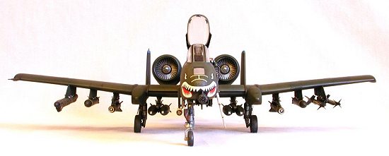
While the A-9 was relatively conventional in layout, the A-10 was downright ugly. The engines were mounted in separate pods at the rear of the fuselage while the empennage featured a pair of slab-sized fins and rudders. The main gear semi-retracted into pods on the wings, leaving the wheels partially exposed. The bulbous nose, reminiscent of a Jurassic-era ruminant, mounted the tank-busting 30 mm gun. It was a stark contrast to Northrup’s entry, even more so compared to the new generation of ‘teen’ fighters then in development.
Nevertheless, the Air Force selected the A-10 for production, officially christening it the Thunderbolt II. Pilots assigned to fly it had a different perspective, however, preferring the moniker "Warthog", or more simply "The Hog". Manufacture began at Fairchild’s plant in Hagerstown, Maryland in 1975. The flight-test program had demonstrated the excellent low speed maneuverability necessary for the mission and the armor protection gave aircrews added confidence in the aircraft. The first A-10 units deployed to Europe in 1978.
The ultimate test of any combat aircraft is, of course, combat. During the Gulf War, Warthogs performed remarkably, operating under extremely austere and demanding conditions. In roles not originally envisioned for the aircraft, A-10s were assigned to RESCAP, Forward Air Control, and Scud-busting duties, in addition to over 8,100 close air support sorties. The armor plate and redundant systems brought many a Hog home after massive battle damage that doubtless would have claimed less-robustly designed types.
With the subsequent draw-down of U.S. forces following the end of the Cold War, the Air Force began mothballing large numbers of aircraft, including Warthogs. Davis-Monthan AFB is now home to a sizable contingent of Hogs, though officially their status is regarded as ‘flyable storage’. Other A-10s have been transferred from the active force to Air Guard and Reserve units while planners at the Pentagon ponder the next-generation replacement. It most certainly will be a tough act to follow.
|
THE KIT |
Revell’s A-10 Thunderbolt II kit contains 95 parts molded in light gray, with the two-piece canopy, wingtip position lights, tail prop, and HUD glass molded in clear. A text-less instruction sheet offers sequential assembly steps, a brief history of the aircraft, and a four-view drawing of the pre-production prototype "JAWS" paint scheme with generics colors specified. The decal offers no optional markings.
The surface detail consists of raised panel lines with recessed vents, louvers, scoops, and movable control surface demarcations. Gear well detail is sparse at all three positions, while the GAU-8 cannon is overly simplified with lackluster detail.
The engine nacelles feature separate fan and tailpipe inserts, though the fans are situated too close to the intake fronts. A boarding ladder is included and may be attached in the deployed position if desired. A separate door covers the well if the ladder is omitted.
 The cockpit is total
conjecture with fictitious details molded in raised relief. The one-piece seat
is the early Douglas ‘Escapac’ unit and very poorly depicted. A separate
control yoke and HUD round out the interior components.
The cockpit is total
conjecture with fictitious details molded in raised relief. The one-piece seat
is the early Douglas ‘Escapac’ unit and very poorly depicted. A separate
control yoke and HUD round out the interior components.
The well-molded canopy can be displayed open but none of the complex actuator mechanism is furnished. Separate clear parts are used to represent the wingtip position lights. Several antennas and sensors are missing while others are simplified.
The landing gear seems correct, though many details have been omitted. Ballast will undoubtedly be necessary to prevent the completed model from assuming a ‘tail dragger’ pose, though a clear tail prop is provided as aid and comfort to forgetful modelers. A ‘Pave Penny’ pod with pylon is included, but the unsophisticated molding is less than convincing.
The wing has the correct dihedral to the outer panels with separately-molded external aileron mass balancers. The inboard leading edge slats are molded integral to the wing tops, though the end plates as well as the fuselage strakes are separate items.
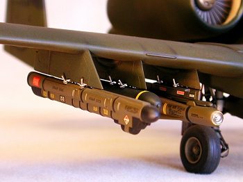
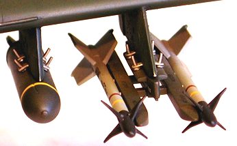
The external stores consist of two different prototype ECM pods, 7 Mk 20 Rockeye CBUs, and 6 AGM-65 Maverick missiles with a pair of the seldomly-used triple launch rail assemblies. Detail on these pieces as well as the pylons is soft and murky at best.
The kit’s decal sheet includes one scheme, the aforementioned prototype "JAWS" aircraft assigned to the 57th FWW at Nellis AFB, circa 1977. The decals are usable provided the surface is sufficiently glossy prior to application. As minimal service stenciling is provided, the modeler would be well-served by supplementing these items from alternate sources.
As an aside, the box-top art for this kit features a photograph of Tamiya’s A-10, painted in colors appropriate for the Revell-supplied decals. A re-issue of this kit in 1981 sported a picture of the actual Revell model on the box-top wearing the standard Euro I camouflage pattern and included the proper operational markings for that scheme.
|
CONSTRUCTION |
 Note:
Note:
This model was one of a matched pair built concurrently and cooperatively by myself and fellow master modeler (and good friend) Kent Veltman twenty-one years ago. As such, it is difficult (nigh impossible) for me to specifically recollect which of us actually performed what assembly. Suffice it to say, for ease of reading the following text I may refer to the builder in the first person (‘I’,’ me’,’ my’, etc.). Bear in mind, however, this was a joint undertaking.
Construction began by taping the major components together to calculate the ballast necessary to achieve an acceptable center-of-gravity in order to keep the nose wheel in contact with the ground. The C/G equation worked out to two one-ounce wheel weights, a ‘Woodland’ scenery tree trunk (honest!), and a boatload of BBs.
 The mock-up was then
disassembled and each part was individually detailed. Vents, scoops, and exhaust
ducts were drilled out to amplify the illusion of depth, while louvers were
replaced by photo-etched stainless steel grates. Fine mesh screen was used for
the gun gas purge vents and APU exhaust ports.
The mock-up was then
disassembled and each part was individually detailed. Vents, scoops, and exhaust
ducts were drilled out to amplify the illusion of depth, while louvers were
replaced by photo-etched stainless steel grates. Fine mesh screen was used for
the gun gas purge vents and APU exhaust ports.
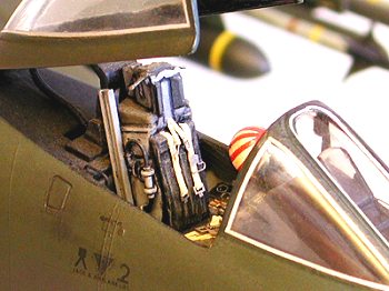
Sad as they were, the kit’s instrument panel and cockpit tub were used, after adding enough details to impart a ‘busy’ look to the office. The Douglas Escapac seat was treated in similar fashion, while the stick was replaced with a modified F-15 unit pirated from the Monogram kit. The completed cockpit was cemented to the right fuselage half while attention was focused on installing the ballast.
As the gun access panel and fairing are molded together as a separate piece
(allowing relatively un-obstructed access to the nose), the wheel weights were
 attached in flanking positions
below the cockpit tub with Crazy Glue, then the fuselage was assembled. The
pre-shaped lead tree trunk was inserted into the nose cavity and glued with
five-minute epoxy. Before this adhesive cured, the requisite number of BBs were
pressed into the glue.
attached in flanking positions
below the cockpit tub with Crazy Glue, then the fuselage was assembled. The
pre-shaped lead tree trunk was inserted into the nose cavity and glued with
five-minute epoxy. Before this adhesive cured, the requisite number of BBs were
pressed into the glue.
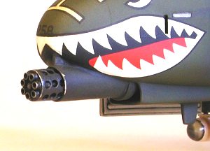
The nose gear well’s side wall was attached to the inside of the gun access panel, then the panel itself was glued to the nose. The plastic gun fairing and scavenger vent were removed and replaced with scratch-built metal components, using rectangular brass channel and aluminum tubing. The muzzle brake was likewise addressed using stainless steel tubing for the seven gun barrels and aluminum tubing for the perforated outer sleeve.
 The kit-supplied boarding
ladder was replaced by a scratch-built equivalent made from telescoping sections
of square brass channel with steel wire steps and grab handles. It was painted
yellow then set aside for later installation, after painting and decaling were
complete.
The kit-supplied boarding
ladder was replaced by a scratch-built equivalent made from telescoping sections
of square brass channel with steel wire steps and grab handles. It was painted
yellow then set aside for later installation, after painting and decaling were
complete.
Deviating from the instruction sheet, the empennage was glued together and attached to the fuselage as a subassembly. The fit was poor, especially on the ventral mating surfaces. Repeated fills with CA were necessary to fill the gaps.
The engine nacelles, sans the intake rings and compressor fans, were assembled and test-fitted to the fuselage. The fit here was horrible and beyond the ability of CA or putty to fix. Plastic shims were necessary to build up the mating edges of the fuselage, but even then, filler was still required for an acceptable appearance.
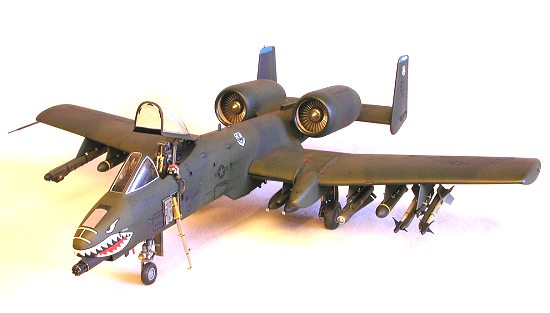
 The inner concave surfaces
of the intake rings were built up with multiple layers of Squadron ‘Green
Stuff’, then sanded smooth to allow the fan fronts to fit behind them. Prior
to installing the fans, they were finished with silver ‘Rub ‘n’ Buff’,
then washed with India ink. The intake rings were painted gloss white on the
interior, fitted over the completed fans, then cemented to the nacelles with CA.
The inner concave surfaces
of the intake rings were built up with multiple layers of Squadron ‘Green
Stuff’, then sanded smooth to allow the fan fronts to fit behind them. Prior
to installing the fans, they were finished with silver ‘Rub ‘n’ Buff’,
then washed with India ink. The intake rings were painted gloss white on the
interior, fitted over the completed fans, then cemented to the nacelles with CA.
The wings were assembled with Crazy Glue then sanded extensively to rid them of seam lines. The concave lower wingtip areas were particularly troublesome, requiring several fill-and-sand sessions to get them smooth. The molded-on inner slats were removed with a coarse file and replaced with airfoil-shaped sections of K & S hollow aluminum strut. The kit’s endplates were modified to fit the new slats and attached with CA.
The plastic ventral strakes were discarded in favor of sheet-aluminum
 equivalents attached with
gap-filling Hot Stuff. After sanding them flush to the fuselage sides the wings
were attached. This fit was worse than that of the engine nacelles. Huge gaps at
the trailing edge fillets provided hours of modeling bliss. With the wing
fillets filled and sanded smooth, the pods for the main gear were cemented to
the wings in a relatively painless operation.
equivalents attached with
gap-filling Hot Stuff. After sanding them flush to the fuselage sides the wings
were attached. This fit was worse than that of the engine nacelles. Huge gaps at
the trailing edge fillets provided hours of modeling bliss. With the wing
fillets filled and sanded smooth, the pods for the main gear were cemented to
the wings in a relatively painless operation.
At this point it became apparent that the model was extremely heavy, with the gross weight increasing with each added component. The canopy and windscreen had yet to be added plus there was the small matter of the ordnance and pylons…
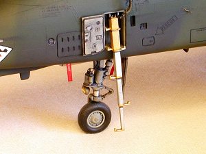
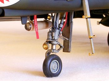
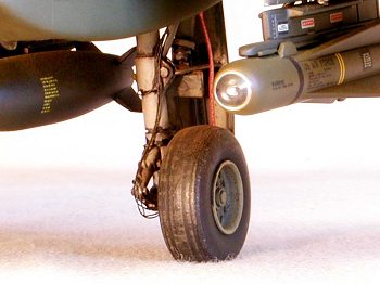
Clearly, the plastic gear struts could not accomplish their mission. Mil-Spec
replacements were fabricated using steel music wire, brass and aluminum tubing,
and plastic detail parts removed from the original kit pieces. Fine wire was
used as hydraulic brake lines for the main gear and as electrical
 harnesses for the landing/taxi
lights, while MV lenses were drafted to replicate the bulbs. The Revell wheels
were used after flattening the tires and adding some detail to the disc brake
calipers.
harnesses for the landing/taxi
lights, while MV lenses were drafted to replicate the bulbs. The Revell wheels
were used after flattening the tires and adding some detail to the disc brake
calipers.
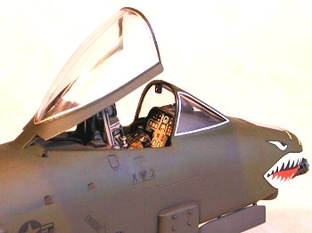
The prominent HUD and canopy actuator areas were scratch-built using wire, scraps of aluminum sheet, and various bits from the modeler’s best friend, the spares box. When the instrument panel combing had been sufficiently detailed and painted, the windscreen was attached using Testor’s liquid cement. The canopy received a triplet of Waldron photo-etched mirrors.
The pylons were next, and every one of them were detailed with two sets of sway braces then installed with CA. Much sanding and filling was required to arrive at an acceptable appearance. The aileron mass balancers were attached without incident, then the final details were added to the airframe.
 The Pave Penny pod was
removed from its attached pylon and detailed, using an MV lens set into the
front and covered by a chunk of smoke gray Lucite. Crazy Glue was used, and when
dry, the Lucite was shaped into a ballistic dome and polished with Brasso. Pins
were installed to allow for reattachment to the pylon along with a pair of small
sway braces made from aluminum sheet. The pylon was glued into position on the
fuselage with Testor’s liquid cement while the pod was painted gloss white and
set aside for later installation.
The Pave Penny pod was
removed from its attached pylon and detailed, using an MV lens set into the
front and covered by a chunk of smoke gray Lucite. Crazy Glue was used, and when
dry, the Lucite was shaped into a ballistic dome and polished with Brasso. Pins
were installed to allow for reattachment to the pylon along with a pair of small
sway braces made from aluminum sheet. The pylon was glued into position on the
fuselage with Testor’s liquid cement while the pod was painted gloss white and
set aside for later installation.
A bulletproof pitot tube constructed of aluminum tubing and brass wire replaced the kit’s fragile plastic part on the starboard wing. The various blade antennas, removed during the fuselage assembly, were supplanted with new ones made from Plastruct sheet. The FM ‘towel rack’ antenna below the cockpit was made from .026" brass wire and bent into the proper configuration, while further aft, the fuel dump mast below the engines was duplicated using a beveled piece of aluminum tubing, partially crushed into a oval cross-section.
The exterior lights were fashioned from small pieces of transparent red and green polystyrene, filed and sanded to shape then polished with Brasso and a Q-Tip. White MV lenses were used as a rear position light and as anti-collision beacons on the wingtips.
The model was given a light sanding overall with 320-grit then carefully inspected for flaws. The Squadron putty used to fill gaps at the engine nacelle-to-fuselage joints had shrunk slightly, so Hot Stuff was used over the filler to build the area up again. After re-sanding the nacelles, the panel lines lost during the assembly were re-scribed, then it was off to the paint shop.
|
PAINT & DECALS |
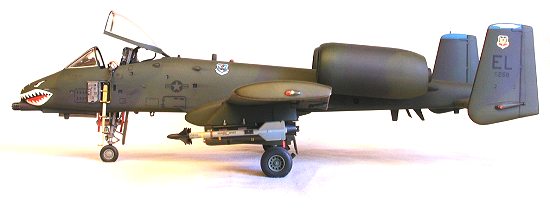
The first of these two models was painted and decaled to represent the JAWS aircraft as featured on the box-top artwork. It was traded away long ago to become somebody’s cherished family heirloom or more likely, garage-sale fodder (take your pick). This model was originally slated to wear the Mask 10A scheme, consisting of dark and light ghost grays applied in a symmetrical feathered shadow pattern.
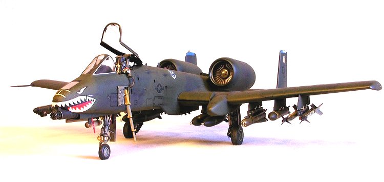
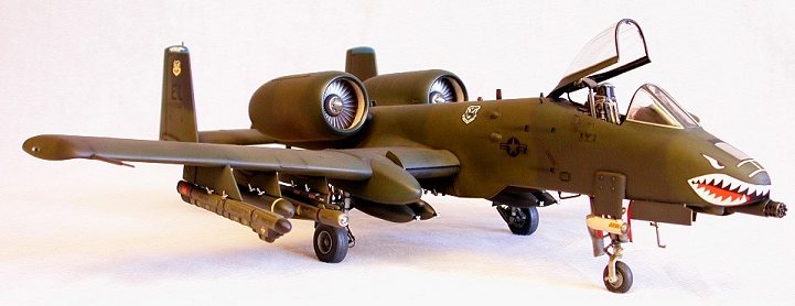
However, midway through this kit’s assembly the Air Force developed and adopted the Euro I scheme, consisting of Dark Green (FS 34092), Medium Green (FS34102), and Dark Gray (FS 36081) in a full wrap-around configuration. The paint job looked infinitely more interesting than the Mask 10A colors and a visit with Dana Bell secured a set of four-view drawings illustrating the complete pattern arrangement.
 Pactra gloss enamels were
carefully mixed to color chips in the FS 595a and sprayed freehand using Dana’s
drawings as a guide. Gear wells, struts, wheel hubs, and the ladder compartment
and door were painted neutral gray (approximately FS 36270), while the tires
were done in Pactra Scale Black then dry-brushed with flat white. A rectangle of
Bare Metal foil was used to cover the air refueling slipway door (unpainted on
the actual aircraft).
Pactra gloss enamels were
carefully mixed to color chips in the FS 595a and sprayed freehand using Dana’s
drawings as a guide. Gear wells, struts, wheel hubs, and the ladder compartment
and door were painted neutral gray (approximately FS 36270), while the tires
were done in Pactra Scale Black then dry-brushed with flat white. A rectangle of
Bare Metal foil was used to cover the air refueling slipway door (unpainted on
the actual aircraft).
The first unit to wear the new Euro I scheme was the 81st TFW at RAF Bentwaters in England. Decals for this outfit were cobbled together from various MicroScale sheets and applied directly to the glossy finish. MicroFlat was used to seal the decals and provide a suitable surface for weathering effects.
An enamel wash was used to highlight the major doors, hatches, and movable control surfaces. When dry, powdered graphite applied with a large brush simulated cordite smudges and exhaust stains. Finally, powdered pastel chalks were dusted over selected areas to lighten them and create artificial shadows. A second coat of MicroFlat was applied to seal the weathering.
At this point, Kent and I agreed that the model looked so nice it would be a
shame to overdo things by adding a max load of ordnance. Consequently, the Pave
Penny pod was press-fitted to its pylon while the boarding ladder and its door,
along with the canopy were affixed using Micro Liquitape. A small piece of scrap
photo-etched fret was used as an AOA transducer on the left side below the
canopy, while on the right side a re-shaped pin head was installed as an outside
air temperature probe. The ‘Hog’ was finished.
|
ADDENDUM |
 This model served sedately
in my collection for ten years, requiring little more than periodic dusting and
cleaning. In 1991, after the Gulf War, I decided to re-mark the aircraft and add
the ordnance typical of Warthogs shown on nightly news segments during the air
campaign.
This model served sedately
in my collection for ten years, requiring little more than periodic dusting and
cleaning. In 1991, after the Gulf War, I decided to re-mark the aircraft and add
the ordnance typical of Warthogs shown on nightly news segments during the air
campaign.
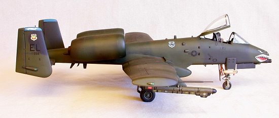
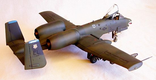
The 81st TFW insignias and ‘WR’ tailcodes were carefully sanded off and replaced by decals from SuperScale’s 48-432 sheet, depicting an A-10 assigned to the 74th TFS, 23rd TFW. The sharkmouth pieces required some easing cuts and SolvaSet to make them behave, but otherwise presented no major problems. The outside fins needed some minor touch-up to restore the camouflage colors, and I decided to paint the fin tips medium blue rather than rely on the SuperScale-provided decals. A light coat of Testor’s flat lacquer completed the re-marking operation.
 I gave the kit’s
original Escapac seat the old heave-ho and replaced it with a Verlinden resin
ACES II unit, detailed with a Model Technologies photo-etched buckle set, paper
belts, short lengths of Plastruct "H" beam, and small-diameter wire
(this should’ve been done years ago!).
I gave the kit’s
original Escapac seat the old heave-ho and replaced it with a Verlinden resin
ACES II unit, detailed with a Model Technologies photo-etched buckle set, paper
belts, short lengths of Plastruct "H" beam, and small-diameter wire
(this should’ve been done years ago!).
A prototypical ordnance load-out was created and installed using pieces from the various Hasegawa weapon sets and a scratch-built dual Sidewinder launch rail adapter for Station 1. Brass wire pins were used to hang the items on their respective pylons.
A few additional mods would be necessary to fully update this model (new gun gas deflector, "slime lights", GPS antenna, etc, etc), but by the time I get around to it the Warthog will probably pass into history.
|
CONCLUSIONS |
After the initial debut and one or two re-issues this kit was discontinued in the mid ‘80s. Following the merger of Revell and Monogram some ten years later, it was permanently retired as Monogram’s proprietary A-10 moldings are arguably much better. Yet at the time of its release the Revell kit was the best looking quarter-scale Warthog available in terms of overall shape and proportion.
The level of detail is well below contemporary standards and the fit will not engender fondness among modelers raised on a steady diet of wonderkits. However, the kit may still be encountered on swap-meet tables, usually at deeply discounted prices. If a modeler intends to buy aftermarket resin castings to replace a kit’s cockpit, wheels, ordnance, etc, it makes no sense to purchase an expensive model when so much of its tooling will be discarded.
In that case, what should matter most is shape, scale, and correct airframe proportions and in my opinion, this kit is still the best. Blasphemous as it may sound, I would select this model over any other 1/48th scale Warthog, even if someone else were paying the freight. Of course, I enjoy the challenge of building a model as opposed to the ennui of merely assembling a kit. In that regard I qualifiedly recommend this A-10 only to those modelers daring enough to stretch their skills beyond box-shaker brilliance.
|
REFERENCES |
Ó May 2001 by Roger M. Jackson
First Time North American Rights To Scott Van Aken and ‘Modeling Madness’
If you would like your product reviewed fairly and quickly by a site that averages over 2,500 visits a day, please contact me or see other details in the Note to Contributors.