| KIT #: | 48063 |
| PRICE: | $51.00 SRP |
| DECALS: | Six options |
| REVIEWER: | John Summerford |
| NOTES: | No ordnance though markings are supplied |
| HISTORY |
According to the box lid:
“The M-346 Master is an advanced jet trainer and light strike aircraft. Initially a joint Alenia Aeromacchi/Yakovlev venture, the partnership dissolved in 2000 and the M-346 was developed separately from the Yak-130. First flown in 2004, the M-346 is now fully operational with the air forces of Israel, Italy, Poland, and Singapore.
As published by Air Force Technology, the M-346 Master is an advanced and lead-in fifth-generation fighter trainer. The M-346 provides combat pilot training for front-line fighters with high angle-of-attack capability. Powered by a pair of Honeywell F124 turbofan engines, it is capable of transonic flight without an afterburner. During the process, the twin concepts of “design-to-cost” and “design-to-maintain” were adhered to, reducing acquisition and operational costs. The per flying hour costs of the M-346 are reportedly one-tenth of those of Eurofighter Typhoon. Outside of the training role, the M-346 was designed from the outset to accommodate operational capabilities including combat missions such as close air support and air police duties.”
 “The M-346
is equipped with a total of nine hardpoints, capable of carrying external loads
up to 3,000 kg while maintaining a high thrust-to-weight ratio; stores
management data can be presented upon any of the multifunction displays in the
cockpit. The radar cross-section of the M346 in a standard configuration is
reportedly 20 square meters; this can be reduced to a single square meter by
installing a low-observability kit which has been developed for the type. Other
self-protection systems that can be fitted include a radar warning receiver,
flares and chaff dispensers, and active electronic warfare systems according to
Alenia Aermacchi the kit provides "excellent levels of survivability and
effectiveness when operating in hostile theatres". Other equipment that is
optionally installable upon the M-346 includes targeting pods, a tactical
datalink, and multi-mode fire-control radar.
“The M-346
is equipped with a total of nine hardpoints, capable of carrying external loads
up to 3,000 kg while maintaining a high thrust-to-weight ratio; stores
management data can be presented upon any of the multifunction displays in the
cockpit. The radar cross-section of the M346 in a standard configuration is
reportedly 20 square meters; this can be reduced to a single square meter by
installing a low-observability kit which has been developed for the type. Other
self-protection systems that can be fitted include a radar warning receiver,
flares and chaff dispensers, and active electronic warfare systems according to
Alenia Aermacchi the kit provides "excellent levels of survivability and
effectiveness when operating in hostile theatres". Other equipment that is
optionally installable upon the M-346 includes targeting pods, a tactical
datalink, and multi-mode fire-control radar.
“Combat missions can also be performed by the M-346, having been designed to be rapidly reconfigured in the field into a combat aircraft capable of performing ground attack, anti-shipping, and aerial combat missions, in a "home defense" capacity. Various munitions can be carried, including a 12.7mm gun pod, IRIS-T or AIM-9 Sidewinder air-to-air missiles, various air-to-surface missiles, anti-ship missiles, free-fall and laser-guided bombs and rockets, reconnaissance pods, and electronic warfare pods; weapon aiming is performed using the helmet mounted display and the multifunction displays. All main systems are duplicated, and the flight system reconfigurable, to increase survivability and functionality in the event of battle damage being sustained. The aircraft has a maximum range of 1,470 nautical miles when outfitted with a maximum of three external fuel tanks, this can be extended via in-flight refueling via a removable refueling probe.”
| THE KIT |
Three bags contain 131 gray plastic parts for the airframe. Another bag has a sprue of 13 clear parts. Pylons and ordinance on three plastic sprues are inside two bags and total 112 parts. The fret of photoetch parts holds 26 parts. If I hit the right buttons on my calculator, that totals 282 parts. Molding details are sharp and panel lines are petite.
 Decals
printed by Cartograph are provided for the four air forces mention above, plus
two prototype aircraft. In addition to the markings found on the main sheets, a
smaller sheet has the markings for the various ordinance that could be loaded
and a strip of stencils common to all aircraft.
Decals
printed by Cartograph are provided for the four air forces mention above, plus
two prototype aircraft. In addition to the markings found on the main sheets, a
smaller sheet has the markings for the various ordinance that could be loaded
and a strip of stencils common to all aircraft.
The instruction booklet is 22 black and white pages long. Assembly is broken down into 31 steps. Color call-outs are for MIG, Vallejo, Gunze Mr. Color, Tamiya, and Humbrol paints, with notes referring to the MIG numbers. A painting chart cross references the other brands. There are slight differences between the airframes flown by the different air forces and the diagrams give detail drawings noting those variations.
| CONSTRUCTION |
Step one is about building the seats. Note that there are slight differences between the pair. I didn’t want them to be set aside for later gluing into the cockpit tub, so I skipped forward to steps 5 and 6 to assemble the main wheel bays and the intake trunks plus the exhausts. While paint and glue were curing, I switched back and forth between earlier steps regarding the cockpit tub and the nose gear.
Each main wheel bay is composed of four neatly interlocking parts and also the strut hinge and retracting arm. Somehow, I had difficulty getting the hinge lined up correctly on the second bay and I could see that it was not set at the same angle as the first one. I dealt with it later when I attached the main gear leg. Once the main wheel bays are in place, the intake trunks slide into place. The fit is very good and I used just a spot of putty on one corner. The intake lips can be glued on at this point, however I left them off for painting separately and to be added during final assembly.
 Parts
were fitting together nicely so when I went to glue the fuselage side to the
tub, I was surprised to discover a gap between the cockpit tub, the front
coaming and the fuselage side. The instrument panel glues to the underside of
the coaming and that assembly is glued to the floor of the tub via the
instrument panel. While trying to figure out what the problem was, I noted that
in step 11 part of the fuselage sides attach to the tub and under the coaming. I
detached one piece from the sprue and found that it slides between the tub and
the coaming. I used it as a jig to hold the coaming in the proper position.
Parts
were fitting together nicely so when I went to glue the fuselage side to the
tub, I was surprised to discover a gap between the cockpit tub, the front
coaming and the fuselage side. The instrument panel glues to the underside of
the coaming and that assembly is glued to the floor of the tub via the
instrument panel. While trying to figure out what the problem was, I noted that
in step 11 part of the fuselage sides attach to the tub and under the coaming. I
detached one piece from the sprue and found that it slides between the tub and
the coaming. I used it as a jig to hold the coaming in the proper position.
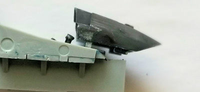
The nose wheel bay is built up around the gear leg. If you want to add the leg later, you can cut the locating pins off of the trunnion and glue a spacer piece to the roof of the bay and glue the trunnion to it. I used a cradle for the model that accommodates the extended leg and didn’t have any problems. The gear builds up nicely.
 After the
nose gear well was in place, I glued a piece of lead in front of the well to
keep the model on the nose wheel. There is not any mention of ballast required
and the model may not need it but I added it just to make sure. (There is space
in the nose cone for ballast too.) I glued the sides to the tub and set it aside
to cure overnight. It might have been better to glue that assembly right away
before everything hardened. The next day I found that the fit to the bottom of
the fuselage was not very good. I had to file some material from the roof of the
wheel well to get rid of the interference. (I’m sure that I didn’t get the roof
piece into the proper position.) One side was pinched in too far so I used piece
of a toothpick as a spacer to pry it apart from the tub. It took some pressure
to get the cockpit assembly to settle in to the lower fuselage, but once there,
the seam looks like a molded panel line.
After the
nose gear well was in place, I glued a piece of lead in front of the well to
keep the model on the nose wheel. There is not any mention of ballast required
and the model may not need it but I added it just to make sure. (There is space
in the nose cone for ballast too.) I glued the sides to the tub and set it aside
to cure overnight. It might have been better to glue that assembly right away
before everything hardened. The next day I found that the fit to the bottom of
the fuselage was not very good. I had to file some material from the roof of the
wheel well to get rid of the interference. (I’m sure that I didn’t get the roof
piece into the proper position.) One side was pinched in too far so I used piece
of a toothpick as a spacer to pry it apart from the tub. It took some pressure
to get the cockpit assembly to settle in to the lower fuselage, but once there,
the seam looks like a molded panel line.
Of course, while getting the cockpit in place I damaged one HUD assembly and knocked off the other. So yes, glue those on after the tub is added. Building the HUDs is a fiddly process. Hindsight being better than my sight, I suggest it be done thusly: make a form from strip stock, or the edge of a board, or what have you. Bend the photo etch mount into shape and paint it. (You might not want to paint the gluing surfaces.) Bevel the bottom edge of the larger, lower clear piece (D-8) and glue it in place. Cut a numbered tab off of the clear sprue to use as a spacer between parts D-8 and D-7. Don’t worry about polishing the area of the filed off number, liquid cement will take care of that. Once the spacer is in place, glue part D-7 on top of it. While this assembly is not true to the spirit of the HUD, the result will be far easier and a much better facsimile than what I achieved.
 With that
drama finished, the bottom wing panels are glued in place and the fuselage top
mated to the bottom. The fit is wonderful! The only place a spot of filler was
needed was on the bottom of the chines.
With that
drama finished, the bottom wing panels are glued in place and the fuselage top
mated to the bottom. The fit is wonderful! The only place a spot of filler was
needed was on the bottom of the chines.
Windshield and canopy were glued in place next. Open or closed canopy options are available as well as with or without imbedded det-cord. The rails glue to the inside face of the canopy, not the bottom. The instructions are vague on their location. Given the mess of my HUDs, I chose to have the canopy closed. Before gluing it in place I masked it. That made it difficult to get it aligned properly and it took some force to get it attached.
Next up in the instructions are the main gear legs. I decided to save those steps for final assembly. I moved on to adding the leading and trailing edge flaps, plus the ailerons and fin/rudder. Again, the fit is superb. There is the option of extending or retracting the flaps, just make sure to remove the correct mounting tabs. (Even yours truly couldn’t mess THAT up!)
There are a lot of little bits and pieces to add to the airframe. I also added the pylon for the centerline fuel tank. Once they were in place it was off to the paint booth.
| COLORS & MARKINGS |
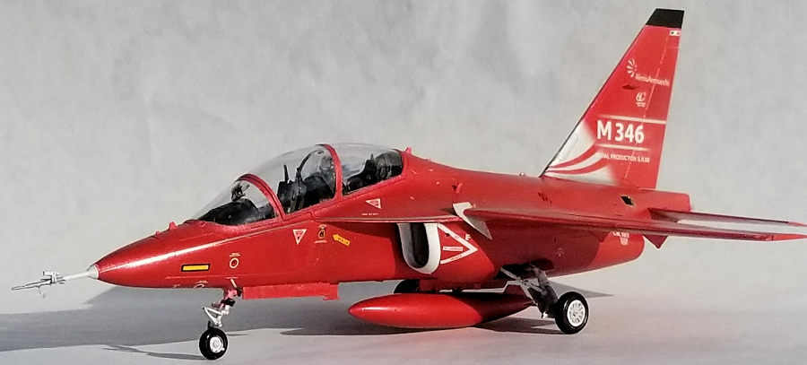
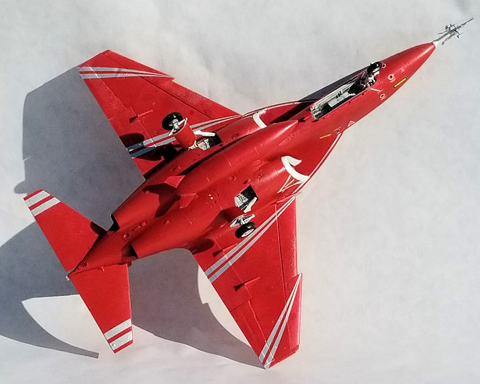
I tend to avoid cammo schemes when I can, not because they’re complicated, but because I like to do something different. I couldn’t resist the metallic red prototype option. I sprayed a coat of rattle can white primer followed by a light sanding with 1000 grit sand paper. MIG red called for in the painting guide was thinned with distilled water and also mixed with retarder and was sprayed on.
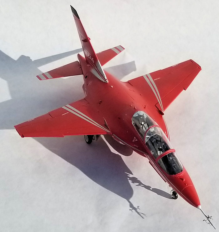
Decaling started on the
underside to test how the decals react. As I was reviewing the markings, I
noticed a 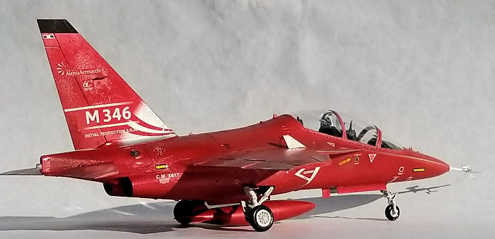 pair
for the fences between the chines and the leading edge flaps. I missed those in
the instruction and the I find the detail view more confusing than helpful. I
interpreted the supplied view as gluing the photo etch fence horizontally on the
flap. The decaling guide and cover illustration give better views. Before moving
on to the decals, a coat of primer was sprayed on both sides of the photo etch
fret. The chines were painted red on one (the inner) side and gloss white (the
outer) side for the decal. Fortunately, the fences slotted neatly in place.
pair
for the fences between the chines and the leading edge flaps. I missed those in
the instruction and the I find the detail view more confusing than helpful. I
interpreted the supplied view as gluing the photo etch fence horizontally on the
flap. The decaling guide and cover illustration give better views. Before moving
on to the decals, a coat of primer was sprayed on both sides of the photo etch
fret. The chines were painted red on one (the inner) side and gloss white (the
outer) side for the decal. Fortunately, the fences slotted neatly in place.
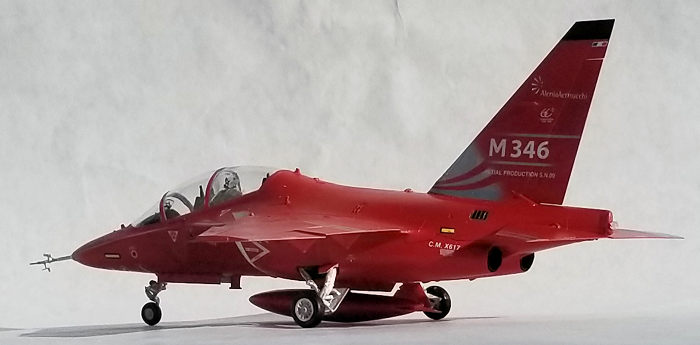
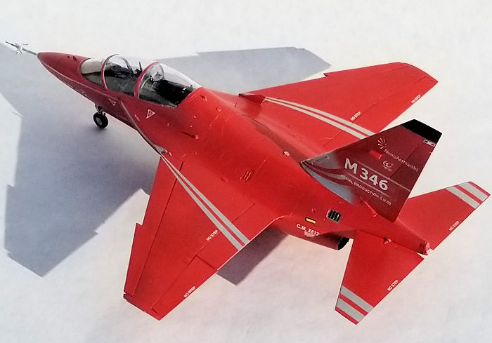
I found that the decals worked very well and responded to Micro Sol/Set. Pay attention to the reference numbers for each side of the airframe. Some minor decals are called out for one side but not the other. I also ran across some confusion between the build instructions and the decals. On the production aircraft there is an air inlet at the base of the fin. On the prototypes it is not there and the instructions have parts for the solid base. The fin decals for both prototypes are designed for the scoop, so I trimmed the extra material off and moved on. The decals were applied over several sessions.
After doing a test of compatibility, I sprayed a coat of clear gloss acrylic from a rattle can of Krylon.
| CONSTRUCTION CONTINUES |
 Everything
was unmasked and touch-ups done. The pre-painted intakes were glued into place
and the main landing gear built up and installed. The main struts are molded
into upper and lower parts and it was the uppers that I glued into the wells
when I installed them at the beginning. After gluing the lower portions on, I
don’t think I got either upper piece at the right angle. The struts ended up
splayed too far apart, so I should not have assembled them during two different
steps.
Everything
was unmasked and touch-ups done. The pre-painted intakes were glued into place
and the main landing gear built up and installed. The main struts are molded
into upper and lower parts and it was the uppers that I glued into the wells
when I installed them at the beginning. After gluing the lower portions on, I
don’t think I got either upper piece at the right angle. The struts ended up
splayed too far apart, so I should not have assembled them during two different
steps.
The only thing that gave me trepidation in doing a prototype is the pitot tube and sensors. Gluing the four photo-etch vanes into place really focuses the mind. I only re-glued one vane. The whole assembly was glued into place and the model was complete. (I then knocked off one vane on the way to the photo booth. I recovered it and then lost it again when, while gluing it back on, the tweezers snapped it into oblivion. I fabricated another one out of .010 sheet.)
| CONCLUSIONS |
When I look at this model, the word “sporty” comes to mind. Charles Lindbergh insisted that the design of the Spirit of St. Louis be as simple as possible, more parts means more chances of failure, which is why the plane had only one engine. There are a lot of parts here. The drama that I experienced was self-induced and the build should have gone faster. Perhaps I became overconfident about the ease of the parts fit despite the complexity and I think the landing gear could be simpler. As a result, I spent around 27 hours on the build without doing much in the way of taking care of seams, or underwing ordinance.
John Summerford
17 September 2019
Copyright ModelingMadness.com
If you would like your product reviewed fairly and fairly quickly, please contact the editor or see other details in the Note to Contributors.
Back to the Main Page Back to the Review Index Page Back to the Previews Index Page