Hasegawa 1/48 F-104S Starfighter
|
KIT # |
PT 20 |
|
PRICE: |
$60.00 AUD |
|
DECALS: |
See Review |
|
REVIEWER: |
|
|
NOTES: |
This is a conversion to the F-104S variant using the Cutting Edge resin conversion set (CEC48627) as well as the Black Box cockpit set, kit no. 48006 for the F-104G/J. Also used were resin sets from Aires, kit no.4100 exhaust nozzle and kit no. 4103 wheel bay. |
|
HISTORY |
The Starfighter was born out of an idea that saw a need for an air superiority day fighter, following the designer, Clarence L. (Kelly) Johnson, holding discussions with pilots flying in the Korean war. What came out of those discussions was a list of requirements that led to the “missile with a man in it”! The Lockheed team submitted an unsolicited proposal to the US Air Force in November 1952, which was for an aircraft both revolutionary and unique in design. The aircraft was to be light, relatively small with a very small span and very thin wing. The Air Force was in the market for an air superiority aircraft but had something in mind that was larger, heavier and delta shaped. The deciding factor in the Lockheed proposal however, was that the price tag was less than the Air Force had anticipated.
The Air Force issued a General Operational Requirements for the development of a lightweight air superiority day fighter on December 12, 1952 and considered hastily prepared proposals from Republic and North American the following month. This included the unsolicited Lockheed proposal, which was announced as the winner. The decision was influenced by Lockheed’s head start in development, based on the conviction of Lockheed and Clarence Johnson, as well as the fact that both other companies were already involved in other fighter programs.
In March of 1953 Lockheed were given a letter contract that resulted in the construction and flight-testing of two prototype XF-104s. Small design changes resulted from initial inspections and the first flight occurred on February 28, 1954. This was an accidental flight as the aircraft became airborne during a fast taxi – yeah right!! The first intentional flight took place on March 4, 1954.
When the XF-104 was ready for it’s maiden flight the intended powerplant, the General Electric J79 engine, was not. The less capable J65 Curtiss-Wright thus powered the aircraft, which showed great promise.
The major difference between this aircraft and others of the time lay in the wings. The configuration used was as a result of trying to gain the best thrust-to-drag ratio, which resulted in the wings being as small and as thin as possible. Each wing was only seven and a half foot from wing root to tip, only 4.2 inches thick at the wing root and a staggering two inches thick at it’s centre. This straight tapered wing gave a more efficient thrust-to-drag ratio than a delta wing. The physics of this showed that whilst the delta wing has less drag in the transonic speed zone when compared with the straight wing, the low-lift capability of the delta wing required twice the area of the straight wing during landings and take-offs. The overall result of this means that a delta wing requires a much bigger surface area and therefore has more drag than the straight wing.
The other ‘unusual’ appearance of the XF-104 was in the presence of a high vertical tail with an all-flying horizontal tail at the top, known as a “T” tail configuration. This configuration resulted in the tail extending above the centre of gravity about as much as the wings extended to each side. This resulted in a large dihedral effect being produced in sideslip maneuvers, which were compensated for by mounting the wings at a ten-degree anhedral, or downward angle to the fuselage.
The continued development of the XF-104 resulted in an empty weight approximately half that of existing fighters at the time, helping to increase the thrust-to-weight ratio and thereby increasing the speed of the aircraft.
The first YF-104 was flown on February 17, 1956 and had the lengthened fuselage, shock cones on the intakes and the nose gear strut at the rear of the wheel bay, rather than the front as on the XF-104. A spine fairing was also added from behind the canopy to the vertical tail. In 1958 the J79-GE-3A engine was replaced with the more reliable –3B unit.
The Starfighter was born and started to break all sorts of records. However, sales within the US military were far from successful and Lockheed looked overseas to salvage the F-104 program. To say that this was successful is a complete understatement, with many countries choosing this aircraft over a variety on offer. Countries such as West Germany, Belgium, The Netherlands, Italy, Canada and Japan were all authorized to produce this aircraft outside the US. By August 1962, F-104s were being constructed in seven countries and on three continents. All the single seat fighters were based on the F-104G design that featured the larger vertical tail and rudder than that used on the F-104A and F-104C. It was the same tail that had been used on the B and D variants. By the mid nineteen sixties, the Starfighter was in use with more air forces and greater numbers than any other US designed fighter.
The penultimate Starfighter, the F-104S, based on the G model, was built in Italy for the Italian and Turkish air forces. This model first flew in December 1966 with the first production aircraft flying two years later on December 30, 1968.
The F-104S differed from its predecessor in that it had a look down radar capable of guiding the AIM-7 Sparrow missile and is classed as a true all-weather interceptor. In addition to this role it is also used as a ground attack aircraft. The J79-GE-19 engine that powers the F-104S is capable of providing 17,900 lbs thrust in the afterburner, more than the J79-11 engine fitted to the F-104G. The F-104S also has up to nine hard points and is able to carry AIM-9B Sidewinders, AIM-7 Sparrows on under wing pylons. The F-104S uses the RED DOG launch rails for the Sidewinder, which can be on the outboard under wing pylons or on the wingtip pylons. The LAU-7 launcher is used for the later Sidewinder version including the AIM-9. The inboard pylon carries fuel tanks, bombs and other ordinance, but does not carry AIM-9s or AIM-7s.
A few other differences are built into the F-104S but the most discernible is the inclusion of two fuselage strakes aft of the trailing edge of the wings, mounted on the lower portion of the airframe. The other noticeable difference is the exclusion of the 20mm Vulcan Canon. The gun port is faired over on all F-104S Starfighters.
The F-104S Starfighter is the subject of this review.
|
THE KIT |
Upon opening the box one finds it jammed pack with sprues, fourteen in all. The decal sheet is very crisp with three different countries being represented; the first is from the Luftwaffe, the second from the Aeronatica Militare Italiana and the third from the Dutch Air Force, 312 Sq K.N.L.
 The sprues are light grey plastic and although there is some flash it is easily
cleaned up. The biggest disappointment is in the ejector pins marks. These
little suckers are everywhere and in some cases damned near impossible to
remove, especially on the control surfaces. Care needs to be taken when removing
these marks as a lot of very fine detail will be lost with an over zealous
approach – my usual style! The clear plastic is just that and very crisp.
Hasegawa also supply a sprue of black plastic plugs to take the
undercarriage pins for the main and forward struts. As I replaced the kit wheel
wells with the Aries resin set, the kit parts have gone into the spares
box.
The sprues are light grey plastic and although there is some flash it is easily
cleaned up. The biggest disappointment is in the ejector pins marks. These
little suckers are everywhere and in some cases damned near impossible to
remove, especially on the control surfaces. Care needs to be taken when removing
these marks as a lot of very fine detail will be lost with an over zealous
approach – my usual style! The clear plastic is just that and very crisp.
Hasegawa also supply a sprue of black plastic plugs to take the
undercarriage pins for the main and forward struts. As I replaced the kit wheel
wells with the Aries resin set, the kit parts have gone into the spares
box.
The instruction sheet is very typical Hasegawa, clear and concise. Considering the number of sprues there are only seventeen assembly stages before you need to look to external painting and decals, assuming you follow the instructions of course!
The box art is very striking and shows the Luftwaffe variant with “Bavaria” along the rear fuselage and a white/ light blue chequered tail adorned with the Bavarian crest, a rampant Lion. The aircraft is from the JBG 32, although Hasegawa informs us that the aircraft is one called “Barbaria”. Nevertheless it was flown during 1983.
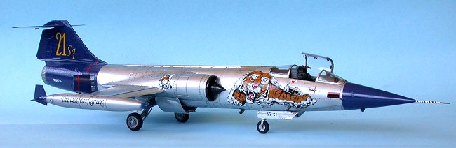
I had chosen to build a Starfighter from the Italian Air Force whose aircraft have some of the most amazing paint schemes of any modern air force. To do this it was necessary to purchase an upgrade resin set from Cutting Edge as the S variant, which I had chosen to build, has a significant amount of differences from the G, which would require more surgery than I was prepared to put into the kit. As is always typical Hasegawa recently released the S variant! It was also necessary to get hold of the decals to build this phenomenally painted aircraft, one that was done up for the Tiger meetings held for NATO countries, again it came from Cutting Edge who have done a series of Starfighter paint jobs. This particular aircraft was from the 21 Stormo, 53 Gruppo and attended the Tiger Meet held in Portugal during 1996.
|
CONSTRUCTION |
The Cockpit
Instead of using the kit parts I had decided to obtain the Black Box cockpit upgrade (Kit No. 48006), which is almost a complete replacement using very few kit bits to complete the “office”. I followed the instructions to the letter, which are very good calling out the colours when required. The kit also comes with the two fuel tanks, although I felt that the kit offerings were superior and used them instead. Following instructions to the letter can sometimes lead to problems as you will see.
Be very careful if you decide to use this kit as the instructions show that the instrument panel and cowling is to be placed after the cockpit tub is sandwiched in between the fuselage halves. If you do this and have connected the control column onto the cockpit tub you will not be able to get the instrument panel in without having to carve something. I swore, I cursed; I ended up breaking it as I tried to get it to fit into the cockpit, ruining my beautiful paint job on the instrument panel. The bloody thing does not fit no matter what you do. The end result was that I cut the top part of the fuselage that covers the cockpit. The side parts of the instrument panel need to be sanded, as did the centre panel, to allow enough room for the whole assembly to sit into the tub. Fortunately the cowling, which houses the camera combining glass, covers this surgery, but not until after my blood pressure had cause a number of gaskets to be blown! In retrospect I would recommend that the instrument panel be fitted before closing the fuselage and then attaching the cowling.
 The other bit of surgery required was on the top coping of the fuselage, where
the side panels attached. The kit requires a slight notch to be cut to allow the
resin sidewalls to fit flush with the fuselage. The sidewalls of the kit need to
be scraped off and the resin parts glued flush onto the kit in order for the
cockpit tub to sit flush.
The other bit of surgery required was on the top coping of the fuselage, where
the side panels attached. The kit requires a slight notch to be cut to allow the
resin sidewalls to fit flush with the fuselage. The sidewalls of the kit need to
be scraped off and the resin parts glued flush onto the kit in order for the
cockpit tub to sit flush.
There was very little reference in the Black Box instructions as to which ejection set to use, as the C-2 and MB I-Q 7 are presented. A loose statement about early German F-104G and late model Italian F-104S using the Martin Baker seat set me on a course and as I was building the latter, I used the Martin Baker seat. Again the painting instructions for both are excellent. The instructions with this set also require you to sand the cockpit floor until the area opens up, as the Starfighter did not have floor.
The canopy frame was covered with Bare Metal Foil and made to sit down with a cocktail stick burnishing the surface. Once attached the three pieces that make up the canopy were covered with Future. OK, in Australia it is called Johnson’s Shine Magic for those who are still looking for it! This sealed the foil strips and gave the whole thing a nice shine in keeping with the rest of the airframe.
The Fuselage and Wings
 The first thing in the construction was to attach the fairing for the 20mm
Vulcan Canon on the port side of the fuselage under the cockpit area. This
variant does not possess such a weapon. The fuselage also required a little
surgery to accept the drogue chute housing supplied in the Cutting Edge
update set. This means that the housing needs to be cut out so that the resin
part could be attached. I cut the notch in each fuselage underside with nylon
twine, gently “sawing” along the panel lines. It came away easily and the new
surfaces were sanding smooth in preparation for the chute housing. I did agonize
over the interior colour that this part and the rear engine housing would be and
ended up using Yellow Zinc Chromate from the Model Master Acryl range.
This was thin enough to be hand painted and still produce a very flat finish.
The first thing in the construction was to attach the fairing for the 20mm
Vulcan Canon on the port side of the fuselage under the cockpit area. This
variant does not possess such a weapon. The fuselage also required a little
surgery to accept the drogue chute housing supplied in the Cutting Edge
update set. This means that the housing needs to be cut out so that the resin
part could be attached. I cut the notch in each fuselage underside with nylon
twine, gently “sawing” along the panel lines. It came away easily and the new
surfaces were sanding smooth in preparation for the chute housing. I did agonize
over the interior colour that this part and the rear engine housing would be and
ended up using Yellow Zinc Chromate from the Model Master Acryl range.
This was thin enough to be hand painted and still produce a very flat finish.
The engine from the kit part was completely replaced by the one from the Aires range (Kit No. 4100), which includes the resin afterburner and the jet nozzles. It also supplies the afterburner ring in photo etch. These parts were painted with Alclad II acrylic paints in a mixture of Jet Exhaust, Duralumin and Magnesium. Any shade was used as long as it looked as though it had been hot! The results are shown below and are fine. I should point out that the use of the Aires kit was a matter of choice as the kit parts are more than adequate and would provide a finished product not so far removed from my efforts. A nozzle was also provided in the Cutting Edge set.
The airframe has a number of navigation lights present and the Cutting Edge set has a variety of coloured plastic pieces to carry out this task, complete with very thoughtfully supplied masks. A very nice touch indeed as it would have been not so easy to do without a Waldron Punch and Die set. The holes for these lights must be drilled out prior to closing the fuselage with one exception, the upper and lower navigation light positions, which may be drilled afterwards.
Once the cockpit had been connected to one half of the fuselage the other part was cemented into place. I did not fit the engine until after I had sprayed the assembly, as I did not want to go through a masking job and run the risk of screwing up the work done on the jet exhaust! I did, however, go through great pains to ensure that it would fit after all the efforts. The other reason was that the rear of the fuselage directly above the exhaust needed to be painted blue and it was easier to leave off the engine until that had been completed.
 The nose cone is a separate part and to this was added the obligatory fishing
lead weight (good job I don’t do much fishing these days. I would have serious
trouble threading the line through my models!), and then attached to the
fuselage. I did not attach the Pitot tube that sits at the front of the beast
at this time, as this would require so many reattachments during the build to
send even a sane man off the deep end. (Just a little nudge is enough for me at
times!) This required a red/white swirl rather like the old Barbershop poles and
was left until all parts were completed.
The nose cone is a separate part and to this was added the obligatory fishing
lead weight (good job I don’t do much fishing these days. I would have serious
trouble threading the line through my models!), and then attached to the
fuselage. I did not attach the Pitot tube that sits at the front of the beast
at this time, as this would require so many reattachments during the build to
send even a sane man off the deep end. (Just a little nudge is enough for me at
times!) This required a red/white swirl rather like the old Barbershop poles and
was left until all parts were completed.
The wings are a very tight fit and require absolutely no filler – a very nice surprise. Hasegawa supply the flight surfaces as separate items and, although the Starfighter at rest did not normally have the flaps deployed, I elected to give a bit of movement and extended the flaps a small amount. I also did the same with the slats and ailerons. All of these parts were covered with Bare Metal Foil as I wished to have a subtle variation from the rest of the airframe. In retrospect I think the use of the foil was more trouble than the final effect was worth. I experienced no end of problems with the stuff not sitting right, especially around the extremely sharp surfaces. Eventually I gave up on some and reverted to spraying the parts.
As this version is an “S” it required two ventral strakes to be added aft of the wing positions. Cutting Edge was a little vague with the placement of these strakes and I ended up guessing as to their exact location using available reference material. They look right and in the end that’s all that matters I guess.
I had also decided to use the pylons for the weapons, despite this aircraft being a “special”. I figured that it would have had the placement for them and wanted to show that the pylons are at ninety degrees to the ground, rather than the wing as is the case on the earlier USA models. To do this it was necessary to drill out the holes for the pylons and specific measurements are given in the instruction supplied by Cutting Edge. I ended up using these and the locating pins on the actual pylons to ensure exact placement.
 The kit fuel tanks were used in preference to the ones supplied by Black Box
as I felt that there was far more detail on them. This is a great testament to
the amount of detail in this kit. I did go to the trouble of using the correct
navigation lights supplied by Cutting Edge on the outside of each tank.
The tanks were given the Alclad treatment and, after a suitable drying
time, were also painted Tamiya X4, Blue at the front and rear, along with
a feathered edge. I also painted the filler points with a red dot, as seen on my
photo reference of the real aircraft, contrary to the instructions. The tanks
were added to the wing tips after all painting had been completed.
The kit fuel tanks were used in preference to the ones supplied by Black Box
as I felt that there was far more detail on them. This is a great testament to
the amount of detail in this kit. I did go to the trouble of using the correct
navigation lights supplied by Cutting Edge on the outside of each tank.
The tanks were given the Alclad treatment and, after a suitable drying
time, were also painted Tamiya X4, Blue at the front and rear, along with
a feathered edge. I also painted the filler points with a red dot, as seen on my
photo reference of the real aircraft, contrary to the instructions. The tanks
were added to the wing tips after all painting had been completed.
The rear wing and rudder were attached, with the latter being offset to the right, following the control settings in the cockpit.
Undercarriage
The kit parts for the wheel wells were completely replaced with the Aires
kit No. 4103. It was necessary to carefully cut away the nose wheel bay as the
kit part is connected to a section of the fuselage. This part was checked to
ensure that the cockpit floor did not obstruct the top of the nose wheel bay. In
the real aircraft there is no cockpit floor, the ejection seat is actually
fitted through the floor and in some earlier models the ejector seat egressed
through the floor! After it was found
 that the rocket powered ejector
seat was driven into the ground, along with the occupant, on low-level ejections
the seat was changed to the upward movement. The reason it had been opted for in
the first place was the concern that the pilot may hit the high tail!
that the rocket powered ejector
seat was driven into the ground, along with the occupant, on low-level ejections
the seat was changed to the upward movement. The reason it had been opted for in
the first place was the concern that the pilot may hit the high tail!
The main undercarriage wells were also matched to the fuselage, but in this case the resin was a straight replacement for the kit parts. Again, it was necessary to carefully pare away the resin to get a good fit.
Both wells were sprayed with Alclad II Aluminium acrylic and details
 picked out, such as the hose connectors, Tamiya Clear Blue, and some
hoses in Gunze Sangyo Tan. They were then given a thin black/grey wash
with watercolours. The main and nose wheel struts were similarly painted with
the Alclad and brake lines added to them. They were then attached to the
relevant bay and the landing lights attached to their contact points. I decided
to use the kit lights, although the MV lenses would have looked better in
retrospect, proving that hindsight is always 20/20!
picked out, such as the hose connectors, Tamiya Clear Blue, and some
hoses in Gunze Sangyo Tan. They were then given a thin black/grey wash
with watercolours. The main and nose wheel struts were similarly painted with
the Alclad and brake lines added to them. They were then attached to the
relevant bay and the landing lights attached to their contact points. I decided
to use the kit lights, although the MV lenses would have looked better in
retrospect, proving that hindsight is always 20/20!
The undercarriage doors were a mix of kit parts and Cutting Edge, the latter being the forward bay doors for the main gear. These doors are also set as almost closed on the grounded aircraft, opening only on cycling the landing gear. All doors were covered with Bare Metal Foil Aluminium and were attached once the airframe had been painted and decaling was complete.
|
PAINT & DECALS |
The colour for the particular aircraft I had decided to build is fairly simple. The majority of the surfaces are painted in high gloss aluminium and the tail section, nose section and leading and trailing edges of the fuel tanks is painted Blue. Simple, or at least that is what was thought. As the body was to be a highly polished natural metal I elected to use the Alclad II acrylic paint range. This is a fantastic product that is sprayed straight out of the bottle. The only stipulation is that you must undercoat the surface first otherwise the paint reacts with the plastic and starts to dissolve the surface. So, first things first the body was sprayed with a fine automotive general-purpose undercoat. This is in keeping with the manufacturers recommendations. Once the surface had been undercoated it was rubbed back with extra fine mesh cloth in preparation for the silver, in this case the Aluminium finish, followed by the high gloss paint (type E). I also sprayed the wheel wells and the undercarriage struts and touched these up with Tamiya XF16, Flat Aluminium, where appropriate. The Alclad II was over sprayed on to the areas to be painted blue, as the blue colour needs to be a feathered edge.
The instructions from Cutting Edge, whose decal sheet I had elected to use, were very explicit about the blue colour, nominating FS 15056 (which was referred to as Blu 5 alta brillantezza) as being correct. (The instructions also point out that Giallo Cromo 15 alta brillantezza mentioned on the colour chart was incorrect). Now I couldn’t find this colour anywhere and initially decided to spray FS 15050 (Blue Angels Blue). Ray Snazel sent me a great colour chart that had FS 15056, the correct colour, being the same as Tamiya X4. This was sprayed on the complete tail area immediately aft of the wing root trailing edge and the nose cone back to immediately forward of the canopy. As it is a high gloss no clear coats were necessary prior to adding the decals, which was the same with the high gloss aluminium Alclad II paints.
 The decal sheet shows a pink
colour immediately aft of the rear canopy, which I believed to be a mistake. I
painted this Gunze Sangyo Tan. In addition the Cutting Edge sheet
shows both intake nacelles as the same colour as the rest of the airframe, high
gloss aluminium, which is not correct. Both the intake cone and leading edges
are painted black, according to actual photos of this particular bird, so I used
Tamiya X18, Semi Gloss Black. This colour does not extend to the fuselage
but stops short top and bottom. The colour at this point is the same as the rest
of the fuselage, High Gloss Aluminium.
The decal sheet shows a pink
colour immediately aft of the rear canopy, which I believed to be a mistake. I
painted this Gunze Sangyo Tan. In addition the Cutting Edge sheet
shows both intake nacelles as the same colour as the rest of the airframe, high
gloss aluminium, which is not correct. Both the intake cone and leading edges
are painted black, according to actual photos of this particular bird, so I used
Tamiya X18, Semi Gloss Black. This colour does not extend to the fuselage
but stops short top and bottom. The colour at this point is the same as the rest
of the fuselage, High Gloss Aluminium.
The decal sheet is part number CED 48042 and is also available in 1:72 for those with better eyesight and patience than myself. The sheet has two aircraft depicted, one is the aircraft I chose, a F-104S ASA from 21 Stormo, 53 Gruppo that was used at the 1996 Tiger Meet held at BA 11, Beja, Portugal. The second aircraft is the Reconnaissance version, RF-104G called “Strega Fighter” 3-24 and was from 3 Stormo, 28 Gruppo based at Villafranca AB, Italy in November 1989.
The decals are superb and go on with minimal fuss. I used Microsol to get them to sit down correctly and although they initially wrinkled it took very little to straighten them out. I also used some of the stencils from the kit sheet, although these items are not indicated on the Cutting Edge sheet. I used my photo reference of this aircraft to confirm some stencils and assumed that other areas of the airframe not affected by the Tiger would stay the same, such as the No Walk stencils on the flaps.
The final assembly job was to attach the Pitot tube, AOA indicators and antennae. I used my references to work out what went where on this aircraft. The nose probe was painted in the red and white swirl with the very end painted in Gunze Sangyo Steel.
Once the airframe had been slightly weathered with a light water based wash the whole model was sprayed with clear gloss acrylic. This helped seal the decals, wash and also those parts of the airframe that had been treated with Bare Metal Foil, including the canopy frames and flaps and slats.
As the model being built was not a service aircraft the pylons would normally be absent, but I am after all a modeller with a modicum of artistic licence. I decided I wanted to display the pylons for the F-104S as this aircraft carried different armament to most Starfighters. Likewise, the pylons are positioned at ninety degrees to the ground surface and not the wing undersurface, as on American Starfighters.
The armament carried by the F-104S has already been listed above so I won’t bore you further!

|
CONCLUSIONS |
This model went together very well and, despite the choice to use after market stuff, can be built into a very good rendition of a Starfighter. As I chose to build an Italian F-104S model it was necessary to use the Cutting Edge resin conversion set, a decision not regretted. This kit provides all the bits and pieces not found in the latest Hasegawa F-104S release, as related by Scott Van Aken in a recent preview Hasegawa 1/48 F-104S Starfighter.
The use of the Alclad II paints is fairly straightforward. The recommended practice of low air pressure (10 to 12 psi) and undercoating the model with an automotive acrylic undercoat is best to be heeded. I have seen the paint attack bare plastic and even have a go at some painted surfaces. The product may be buffed but generally does not require any after spraying work. Follow the instructions and you’ll not go far wrong! My main area of problems lay with the feathered edge of the Blue at the front and rear of the aircraft. I struggled with getting the line vertical for both areas and did the job at least twice. The Alclad painted surface was well up to the task and did not react in any way to masking tape or Blue Tac.
The decals chosen for this kit were fantastic. They are very thin and quite easy to apply, especially the Tiger bits. Cutting Edge has supplied an extra tail for the Tiger, just in case – very thoughtful! I did think that the decals should have included some of the more prominent stencils, or at least the location of them for this particular aircraft. Thank goodness for a wealth of good reference material, especially the World Aircraft Files.
Hasegawa have produced an excellent example of the Starfighter, even without the missile rails. If you decide to go down the track of upgrading an existing G/J to an S variant then you would be well advised to have had some experience at dealing with resin before tackling the job. Otherwise go and grab one and build the famous “Missile with a man in it”!
|
REFERENCES |
Lockheed’s C/NF-104G/J Starfighter, Lock On No. 1, Verlinden Publications 1983, ISBN: 90-70932-01-6
F-104 Starfighter, Kinsey, B.; Detail & Scale Volume No. 38, Airlife Publishing Ltd., England, 1991, ISBN: 1-85310-626-7
F-104 in Action, Friddell,P, Squadron/SIgnal, Aircraft #135, 1993 ISBN: 0-89747-299-3
World Aircraft Files #175, Lockheed F-104, Bright Star Aerospace Publishing
Copyright ModelingMadness.com. All rights reserved. No reproduction in part or in whole without express permission.
If you would like your product reviewed fairly and fairly quickly, pleasecontact the editor or see other details in the Note to Contributors.
Back to Reviews Page 2021