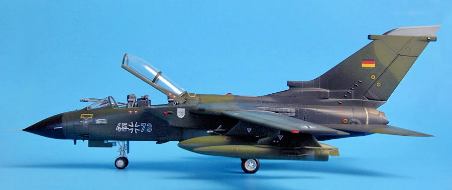
Italeri 1/48 Tornado IDS
| KIT #: | 834 |
| PRICE: | $18.00 'used' |
| DECALS: | Two options |
| REVIEWER: | Martin McClendon |
| NOTES: |

| HISTORY |
Created as a joint venture to share expenses associated with the insanely costly business of producing military aircraft, the Panavia “Multi-Role Combat Aircraft,” better known by the name Tornado, played a vital part in the air forces of four major buyers: Germany, England and Italy (those who had manufactured it) as well as Saudi Arabia. Designed as part of a plan to repulse a Soviet attack into western Europe, the Tornado came in two original variants: IDS (interdiction/strike) and ECR (electronic combat/reconnaissance). The English later developed their own ADV version (air defense variant) to protect the northern approaches to their “sceptered isle.”
First flown in 1974, the Tornado was designed to streak east at treetop level, delivering bombs (including nukes) and taking out air defenses of a Soviet invasion. As such it was equipped with terrain-following radar and carried a “back seater” to manage weapons systems. The IDS version also packed two 30-mm cannon.
The compact airframe had several defining features such as variable-sweep wings. This was intended to give it the ability to operate from short fields with wings swept forward, then swept back for supersonic dash attacks. Variable-geometry inlets were installed to help manage supersonic flight but all the evidence I can find suggests that the plane struggled to maintain supersonic flight and that the inlet ramps were disabled on most aircraft.
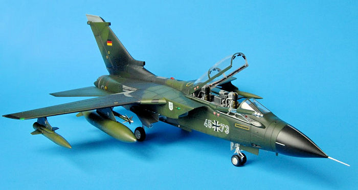 The small size of the
airframe limited internal fuel, and most Tornados were seen with two or four
large drop
tanks. Another unique feature was the
use of thrust reversers, again to aid in short field operations. The
reversers were a clamshell design which directed engine thrust forward over
the airframe, resulting in black sooty deposits all over the vertical
stabilizer.
But the chief defining feature is that same oversized vertical stabilizer, which gave rise to the nickname “The Fin.” Other nicknames included Tonka, Toni, and one German website I saw referred to it as the “Flying Refrigerator” because of its boxy fuselage. This giant fin was utilized as the canvas for a dizzying array of amazing and wonderful artwork. Tornado fins were festooned with all kinds of special paint jobs to celebrate special events, anniversaries, or as part of NATO’s “Tiger Meet” fighter competition. Many such schemes are available both in kits and aftermarket decal sheets. Having served its operators now for 50 years, there is an almost endless variety of camouflage schemes to choose from; one could probably just model Tornados for years and never repeat a paint scheme. But as the years went on, the Tornado fell victim to the now seemingly inevitable move toward painting anything that flies grey.
Tornados were deployed in several conflicts: Gulf War 1991, Balkans peacekeeping operations (where Luftwaffe Tornados made the first German offensive attacks since the end of World War 2), the Iraq war, and Afghanistan, along with several others. (See Wikipedia for complete details.) A few Tornados are due for upgrades that will keep them in service with the Luftwaffe for several more years—they will be the last operational Tornados, all other nations having now withdrawn them from service.
An interesting side note is that for 20 years during and after the Cold War, a detachment of Tornados and hundreds of Bundeswehr personnel were stationed at Holloman Air Force Base, New Mexico. There, Tornado crews practiced their tactical skills in the wide-open skies of the American Southwest. Those planes are identifiable by a large amber-colored badge on the fin.
| THE KIT |
 Esci produced the first 1/48
Tornado, then came the Airfix and Italeri versions. Hobby Boss and Revell of
Germany followed; Revell’s 2014 kit is the definitive one. The Italeri IDS, ADV
and ECR versions have been reboxed a dozen times according to Scalemates, and
also offered by Revell and Testors. This is the first Italeri boxing (1992),
featuring the RAF “Gulf Killer” plane with shark-mouth nose art on the box top.
The plastic is light grey and soft with recessed panel lines. Options: gear up
or down, canopy open or closed, speed brakes open or closed, refueling probe
extended, retracted, or removed. Swing wings and stabilators are movable.
Payloads: bombs, ECM pods, AIM-9 Sidewinders and BOZ chaff dispenser pods, but
no drop tanks as shown on the box art. It seems these were omitted only in the
first run of kits, and Italeri added the missing tanks in future releases.
Additional markings for an Italian Gulf War machine and a Luftwaffe Tornado in
“Norm 83” camouflage.
Accuracy: the overall shape is very good. I opted to buy this kit instead of the newer Revell Tornado owing to the considerable difference in price; the Revell kit has also been reported to be over-engineered. Not so with the Italeri kit! It is frankly under-engineered, with several crude joints and a simplified main landing gear. It is not a shake-n-bake kit. Instructions are adequate. Decal sheet is by Cartograf and is well printed.
| CONSTRUCTION |
Parts were well molded with no flash present in this early boxing. Some have an odd rough surface texture. The only aftermarket parts I used were a set of metal pitot and AOA probes from Master. Everything else was OOB, and I decided to use the “Verlinden Way” of modeling, and add bits of styrene, wire, putty, foil, etc to enhance the kit’s details.
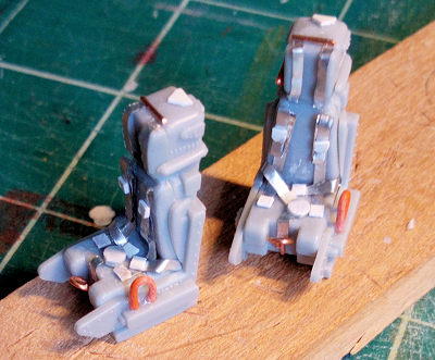 The instrument panels have
raised details. The ejection seats are good but a little generic. I scraped off
the molded belts and added foil risers and belts, as well as the ejection pull
handles and oxygen hookup on the left side of the seat.
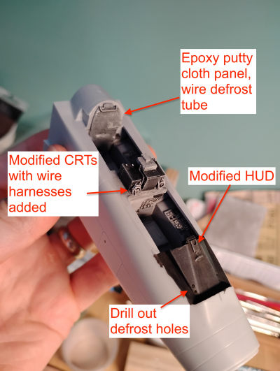
Rear seat instrument coaming: the 3 CRT monitors for the guy in back are so-so. I trimmed back the visors and also reshaped the backs of the monitors, adding wires to the backs as well. The rear cockpit bulkhead has a large gap in the seam and looks lumpy. According to research there is a cloth cover over most of this, and a defrosting tube at the top. I used epoxy putty to mimic the cloth and bits of wire for the tube. The front cockpit coaming got defrosting holes drilled into it, and some switches made of scrap styrene added along the edge as per the research. The HUD opening was drilled out and backed with sheet styrene painted silver and given a drop of Krystal Kleer to represent a lens. The cockpit and seats were based in a light grey custom mixed from Tamiya paints. Then details were picked out with white, black, yellow, light blue (artificial horizon) and red. CRTs were painted black, as if powered down. Everything got a dark oil wash to pop the details and was set aside to dry. Seat back cushions were painted Tamiya Olive Green. The risers/belts are a unique yellow-green color, custom mixed.
 An egg-shaped fishing weight
was installed in the nose cone as per instructions. The cone is slightly larger
in diameter than the fuselage; I glued the top portion flush, and then went to
work with files and sandpaper to remove some of the overhang from the lower
portion to blend it into the underside somewhat.
Gear bays: I didn’t realize this until later, but the main gear bays are too tall. Landing gear are simplified, and have only two points of contact. I added hydraulic actuators from wire with insulation stripped off the lower half. This, I hope, will stabilize the gear by providing a third gluing point. I also added a bulkhead and some other details as per the research. All gear, wheel hubs, gear bays, and gear doors were based in Tamiya Flat White and washed with oils. Gear oleos were wrapped with Bare Metal Foil. The main gear tires were flattened by sanding to give the impression of weight, and brake lines were added from thin wire.
The two halves of the forward fuselage go together well. I removed the locator ridges for the cockpit as they got in the way of proper fitting. Careful gluing led to nice alignment between the halves. The bottom of this section has very shallow panel lines due to the method of molding, so I tried to deepen some of them, a skill which is not my strong point.
The famous fin: the two halves glued up well. I then used a mini-file and sandpaper to sharpen the front edge of the lower fin, as per research. Italeri molded it as rounded, it should come to a soft edge. The fin fits well on the upper fuselage half.
Wings are molded as top and bottom halves, and go together well. Italeri provides clear parts for the side navigation lights on the air intakes, a nice touch. I decided to cut out the wingtip and fuselage spine lights and replace with small chips of polished clear plastic. This took some extra work and was the first time I have done this, but it looks great. Italeri calls for the four wing pylons to be installed before closing up the wing halves, by melting the mounting pin to trap the pylon and make it poseable as the wings swivel. I decided to forgo this feature and glue the pylons on later to make painting easier.
After much staring at research
and test-fitting, I began to suspect that the location of the wing pivot was
inaccurate. It seems like Italeri moved the wing pivot point closer to the
centerline In order to facilitate the swing-wing motion. This results in a
reduced wingspan, and there is a huge gap forward of the wing as well. I printed
out a paper template showing the wings in the 25-degree forward position and
67-degree swept position, and placed the lower fuselage over the template to aid
in positioning the wings. Then it became clear the upper wing gloves are too
small, exposing too much of the inner end of the wing. This
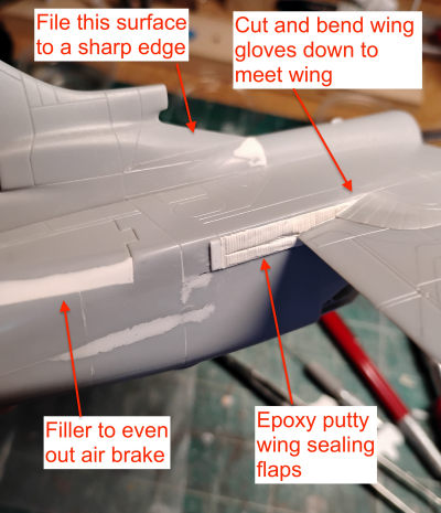 was beyond my power
to fix; I compromised, pushing the wing pivot points about 5-6mm outward on each
side. This results in a reasonable-looking upper wing area and does lengthen the
wingspan closer to scale, around 29 cm. I also pushed the wings further forward
to reduce the gap at the front and permanently glued the wings, making sure to
droop them slightly downward at the tips, as on the real thing. But when fitting
the top half, the upper wing gloves have a significant gap—they should be
touching the top of the wing. I scored along the wing glove seam and cut the
rear half of each free of the fuselage, so I could bend it downward to contact
the back edge of the wing. These wing gloves should not leave any gaps along the
wing surface. I then firmly clamped everything after gluing with good old Testors tube glue and set it aside to dry. Italeri provides little spacer
“sticks” that are glued in to get the height of the fuselage correct in order to
mate it to the forward cockpit portion. These work despite being crude, but
later they needed to be cut and adjusted, when attaching the forward fuselage.
One big omission in detail is the lack of the rear pneumatic wing sealing panels
behind the wings (to allow them to move). This was addressed by backing the void
with sheet styrene and using epoxy putty to sculpt the distinctive ridged rubber
sealing flaps.
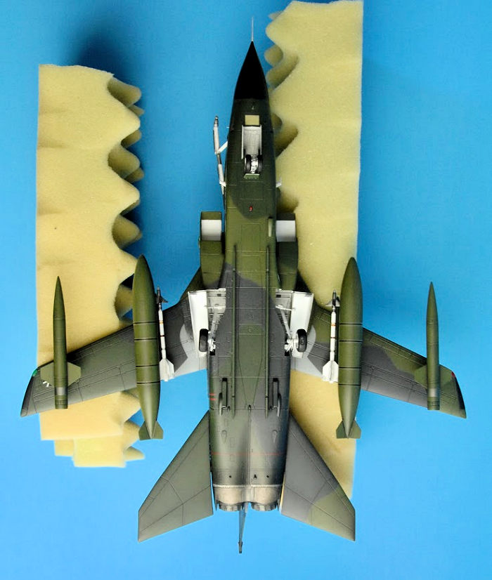
As my kit had no drop tanks, I decided to 3D print this relatively simple shape with my FDM printer. I used Sketchup to trace the shape from a research image, and cut it in half vertically at the center for easier printing. As usual, much filling and sanding to eliminate the printer mold lines. The inner wing pylons seem to be short shot: all the research shows them coming to a sharp point both fore and aft, but they were blunt in my example. Tiny scraps of sheet styrene and white putty were used to correct this. Air brakes were glued closed, but needed shimming, putty, and rescribing to improve fit. The refueling probe was prepared but not yet installed. I carved out the bottom of the probe fairing, which is actually open on the real thing—you can see the fuselage underneath.
Forward and rear fuselage subassemblies are now glued together. There is a small air outlet molded on the left side under the intake, divided by this main joint. It is very visible in photos because it was left in shiny bare metal. I carved it out and built up the rear wall with scrap styrene before joining the fuselage halves. Here as previously stated, much fiddling was needed. I cut the spacer sticks previously installed so that I could exactly match the height of the forward fuselage to the rear, which reduced sanding and filling to almost zero.
 The engine exhaust units are
molded as a separate assembly, conveniently along a panel line that divides
painted from bare metal components. The rear face of the assembly is blank, so I
added some bits of styrene, wire, and a 3D printed bulkhead to give some detail
to this area. The reverser shells were hand painted with Tamiya titanium, while
the nozzles were painted with Tamiya metallic grey. Tamiya aluminum was used to
paint the band of light-colored metal at the forward end of this unit. It would
receive weathering with oils and acrylics later on.
Now it is time to install the air intakes, a project in and of itself. First of all, note that the top of the intake is not supposed to be flush with the top of the fuselage! Several sources I used got this wrong. There should be a gap at the top, which is the bleed air outlet for the intake. The inner side wall of each intake is molded as one piece with the spacer needed to distance it from the side of the fuselage. The result is a gaping hollow spot on the inner intake wall, right at the most visible point of this assembly. I filled this with several coats of Liquitex modeling paste. Then the inner surfaces of all pieces were sprayed with Tamiya flat white. The intake ramps are molded in a lowered, supersonic flight position which I have seen nowhere in the research. They were flattened and modified to fit the now altered inner intake area, and glued in place. The outer intake pieces are then glued to the inner ones, and if you use a little bit of pressure as you position them, you can once again reduce or eliminate major filling and sanding just by careful alignment. But watch out, the thin edges are very prone to dents—I had to go back and repair several nicks and dents in these pieces. I decided to mask off the inner white walls now, while it was easy to access both front and rear openings. The intakes were then glued into place.
There is no intake trunking provided, and the main gear bays, being too tall, stick up visibly as you look into the intake. A blanking plate was installed and painted black here. A lot of plastic manipulation was now used to get the intakes to match up with the rear fuselage sides. A long time was spent test fitting and observing just how and where the problem areas occurred. I used a pair of pliers to gently bend and deform the intake walls of the rear fuselage to get them to match up to the angle of the intakes. The locator pins on the intake bodies, meant to position them against the cockpit, were also removed since they did not allow me to nudge the intakes to the perfect spot. It was also necessary to reduce the height of the rear fuselage deck to even out the bleed air outlets on each side so they matched, by again chopping the vertical spacer sticks and regluing at a lower height. In the end, I got away with only needing a small bit of filler along the bottom seam, and just sanding along the side seams. This removed engraved detail representing auxiliary inlet doors, which I rescribed later, with repeated fillings and sandings as my hands fumbled to hold a straightedge guide and scriber tool on this small surface.
We are not out of the woods yet: the forward wing fairings are the last major hurdle. Each side is made up of two triangular top and bottom pieces, lacking any locator pins or other guides, that are glued together and plopped onto the intake and form the forward opening of the wing slot. After much test fitting and adjusting I used liquid cement to allow me time to move the pieces around slightly to get the best fit. Here I discovered I had placed the wings about 2mm too far back. the wing root is supposed to fill the curving opening in these wing fairings completely, when in the forward position. I used epoxy putty to create an extension of the wing root which is not technically accurate but looks a heck of a lot better than a gaping hole.
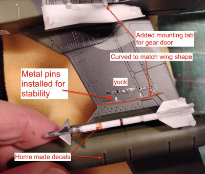
Now we’re getting somewhere! It was time to prepare the canopy. The main portion has a mold line down the center which I sanded out on the outside, but was impossible to remove on the inside, at least with my skill level. I buffed out the scratches and dipped it in Future. Then I carefully masked and hand painted the detonation cord on the inside surface. The front windscreen was Future-dipped and installed with Micro Scale Krystal Kleer and some gaps filled. The canopy was temporarily installed (it will be posed open) and all was masked off for painting. Several other antennas and so forth were installed and the pylons and their loads were prepared for painting too. The upper edges of the pylons are molded straight, so they were filed to match the curve and droop of the wing to reduce any gaps.
| COLORS & MARKINGS |
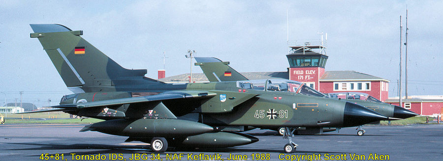
I bought this particular kit because of the markings. Out of all the 1/48 Tornados out there, only this boxing from Italeri contains generic “Norm 83” markings without any of the razzle-dazzle special paint schemes. There is a German aftermarket set for Norm 83, but it would have cost me more than the kit itself to buy it and ship it. “Norm 83” consists of a wraparound camouflage pattern of dark green, light yellowy olive green, and dark grey, used in the 1980s-90s. There is wide variety in the shades used, and bleaching and weathering of the paint means no two planes look alike.
(Here is a photo I took of a pair of JBG 34 Tornados in this scheme back in 1988. Ed)
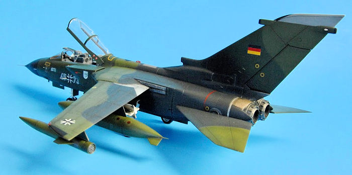
After a coat of Tamiya light grey primer, all areas were examined and joints reworked as needed. Then it was time for camo. My usual method was used: print out the camo scheme in scale, cut and mount paper masks to give a soft edge. The Italeri instructions were hard to read here: the printed dots used for the two greens were virtually identical. I used instructions from a Revell 1/72 Tornado instead. The light green was custom mixed from Tamiya paints: XF-67 Nato Green plus yellow and white. The dark green was mostly XF-58 Olive Green and XF-62 Olive Drab. The dark grey was a mix of black and XF-63 German Grey. There was not much contrast between the dark green and grey colors once sprayed on the model. I adjusted the grey several times before I finally settled for something close to what I wanted. Thereafter, much time was spent masking off and painting various small bits like the nose cone, antenna panels, and the bare grey areas on the wings and fin tip (Model Master Light Ghost Grey), as well as the red warning stripe at the rear. In the past I hand painted details like this, but was very pleased with the results of using the airbrush, despite the added time needed for cleaning the airbrush after each session. 3 coats of Future thinned 50/50 with alcohol were then applied in preparation for decals. The characteristic black soot along the fin was thinned Tamiya black, sprayed in several coats to control the intensity. In the end, the dark colors of the camo make it hard to see the black stains.
 The 32-year-old decals from
the box still worked, but the glue left a milky residue which did not dry clear.
I tried to rinse as much milky gunk off the decals as I could, but this made
them less sticky, which I think led to silvering. Micro Sol decal solutions were
used as well as Future straight from the bottle to try and blend the decals into
the surface. Tip: if you decal solution damages the Future coat by causing a
whitish fog, recoat the area with Future and it will re-seal itself. I spent a
good deal of time with a tiny brush, painting over the silvered areas with the
base colors and adjusting with Future to help blend everything. In this I was
only partly successful, but it looks better than it did at first. Frustration
began to set in, as I was now months into the project and so close to the finish
line, but I remained patient and with careful work brought the overall look from
“shambles” to “acceptable shambles.”
After sealing the decals under more Future, a wash of black oil paint in mineral spirits was applied to all panel lines. After setting for a few minutes, it was wiped away, but areas around the panel lines were blended in to create panel shading and a subtle aging/grime effect.
Final assembly: after 3 light coats of Tamiya matt varnish from a spray can, I set about putting it all together. Here I came close to snatching defeat from the jaws of victory. Try as I might, I could not keep from knocking parts off the model. I broke the right horizontal stabilizer loose soon after installing it. I tried to dribble some CA glue in the gap but ended up getting it all over the paint job. So I removed the stab to clean it up and start again, in the process knocking both inner pylons/drop tanks off as well—and a Sidewinder for good measure. The inner pylons are connected by a weak “butt” joint, a flat surface meeting a flat surface, with only one flimsy plastic pin to give any mechanical advantage, which soon snapped. I tried re-installing them several times only to have them wiggle and snap off again, before finally drilling holes and installing two metal pins to anchor them—should have done that right from the start. Meanwhile I did my best to touch up the paint problems with the stab and reinstall it.
I installed the canopy in the open position. I 3D-printed some jet mirrors and also installed bits of wire to represent the prominent defrosting tubes along the sides. 2 struts made of thin wire were added near the canopy joint as per research. The pitot tubes and AOA probes were installed. Small half-circles of scrap plastic were installed above the horizontal stab pivots: these objects are conspicuous on the real jet but missing in the kit. Main gear door placement is vague in the instructions, and no hinge or locator is provided, so check your references. I made mounting tabs out of scrap styrene for this purpose. The wingtip lights were unmasked and other lights installed. All were painted with Tamiya clear red and green, which I have never used before and highly recommend.
| CONCLUSIONS |
Italeri’s 1/48 Tornado seems like one of those kits that are everywhere, but nobody ever actually builds. We always seem to chase after the “latest and greatest” kits, stuffing them with aftermarket parts on the hunt for the ultimate in accuracy, but I have a soft spot for kits that are in the middle of the accuracy spectrum: better than the first round (Esci) and cheaper than the last round (Revell). The kit has “good bones,” and many satisfying hours can be spent in solving modeling challenges and adding scratch-built details to bring this Tornado to a new level.
| REFERENCES |
Verlinden “Lock-On” series #12: Panavia Tornado IDS, by Willy Peeters
The Internet
20 December 2024
Copyright ModelingMadness.com. All rights reserved. No reproduction in part or in whole without express permission from the editor.
If you would like your product reviewed fairly and fairly quickly, please contact the editor or see other details in the Note to Contributors.