| KIT #: | MM 351 |
| PRICE: | $60.00 |
| DECALS: | Two options |
| REVIEWER: | Donald Zhou |
| NOTES: |
Advantages: Extremely detailed,
entire gun crew included, nice fit. Disadvantages: details somewhat simplified, marking limited and deadly small screws and nuts |
| HISTORY |
The history of U.S. Army self-propelled artillery was a long and arduous one. This was due to no small uncertain facts that well…Let’s just say that the Army sometimes are very conservative, even to its own detriment. Just look at what happened to the M4 Sherman when a replacement, the T26 was ready…and was nearly completely got stomped by men like Leslie McNair, who held on to the dear of all dear mantra of “Tanks are for tank destroyers. Tanks are only for infantry support” even when all the evidence and reality were flying in the face of that now obsolescence mantra!
But one
good thing though, was Leslie was a good artillery officer and he would happily
approve anything that can go long distance and make a big “BOOM”! Despite
initially massive resistance on self-propelled artillery, thinking that towed
pieces will be the norm, Leslie and others gave approval for vehicles like the
M7 to see combat in 1942, most often with the British and looked on with
interests. When the “Priest” became a huge success and extremely popular to the
point where the British can’t get enough of them, even though the 105mm shells
it fires proved to be a logistical nightmare (since the British normally don’t
use that diameter type of shells. Hence why they modified some of the Priests to
fire 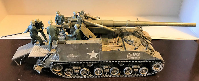 their own 25 pounder shells and renamed it the Sexton). A bigger piece was
quickly developed afterwards, the M12 155mm self-propelled gun. This used a M3
Grant chassis and mounted a copy of the French Cannon de 155mm GPF. The vehicle
was open top. With the Commander and Driver operating the vehicle in closed
copulas at the front. The engine and associated equipment is at the center of
the vehicle, leaving the rear open to be operated in firing mode. A large spade
was added to the rear and deployed to be inserted into the ground to help
against recoil. This pattern, an open rear compartment, a large spade etc was to
become the pattern for many future self-propelled artillery pieces.
their own 25 pounder shells and renamed it the Sexton). A bigger piece was
quickly developed afterwards, the M12 155mm self-propelled gun. This used a M3
Grant chassis and mounted a copy of the French Cannon de 155mm GPF. The vehicle
was open top. With the Commander and Driver operating the vehicle in closed
copulas at the front. The engine and associated equipment is at the center of
the vehicle, leaving the rear open to be operated in firing mode. A large spade
was added to the rear and deployed to be inserted into the ground to help
against recoil. This pattern, an open rear compartment, a large spade etc was to
become the pattern for many future self-propelled artillery pieces.
The cannon was employed after the Normandy landings and enjoyed great success. Although designed in the indirect fire role, sometimes the vehicle was employed in the direct fire role with devastating effect! During the assault on the Siegfried Line, the cannon earned the nickname “Doorknocker” for its penchant at knocking out concrete pillboxes and fortifications. At a range of 2000 yards/meters, well away from enemy counter fire except artillery, a single armor-piercing shell can easily shatter 7ft of concrete. An infantry man who saw the aftermath of such a strike remembered although the concrete pillbox may not have been completely blown up, the occupants were either dead, blown to bits or if they survived, too shell shocked to do anything! Later on, in the Battle of Aachen, once again, the M12 was called upon to knock loose some doors. When the fighting reached a fever pitch and the Germans just won’t come out of houses and the streets, the Americans rolled out the M12. Just like the Russians later on in Berlin, who used their 203mm B4 to great effect, the Americans started to fire 155mm high-explosive shells into any buildings containing German resistance. The German quickly found out the M12 could stay well away from snipers and Panzerfaust and just one 155mm high-explosive round could level half a city block! Afterwards, the mere sight of the vehicle would cause them to surrender or flee in terror. After surrendering the city, the German commander dryly commented that whoever came up with the idea of using the M12 in city streets should be carried out back and shot for “crimes against humanity!” The vehicle earned a new nickname “King Kong” due to its awesome firepower. Such successes quickly spurred the American to develop a replacement.
The idea
for the M40 came about as early as late 1943. 5 prototypes were commission in
early March 1944. The vehicle, then known as the Gun Motor Carriage T83, was
built on an improved M4 chassis that was widened and lengthened and
 used the
HVSS suspension system. Like the M12, the piece had the commander and driver in
front of the vehicle when driving it. The engine and associated equipment were
located in the center, leaving the rear open for operating the artillery piece,
in this case, the improved M1 155mm “Long Tom” cannon. A total of eight crew
members were needed to operate the big gun. The vehicle was tested at Aberdeen
Proving Ground throughout 1944 and production began in February 1945. In May
1945, it was standardized as the 155mm Gun Motor Carriage M40 and nicknamed the
“Big Shot” by crews.
used the
HVSS suspension system. Like the M12, the piece had the commander and driver in
front of the vehicle when driving it. The engine and associated equipment were
located in the center, leaving the rear open for operating the artillery piece,
in this case, the improved M1 155mm “Long Tom” cannon. A total of eight crew
members were needed to operate the big gun. The vehicle was tested at Aberdeen
Proving Ground throughout 1944 and production began in February 1945. In May
1945, it was standardized as the 155mm Gun Motor Carriage M40 and nicknamed the
“Big Shot” by crews.
By the time the new piece entered service in May 1945, the war in Europe was all about over. A single prototype piece, the third prototype T83, was sent to Europe for combat testing, were it acquitted well for itself. Supposedly, it was this vehicle that fired the first shot to open the Siege of Cologne. Some 400 vehicles were produced in preparation for the Invasion of Japan but of course, that never came when the two Big Bombs were dropped on Hiroshima and Nagasaki. The cannon’s baptism of fire came during the Korean War, where it, along with other equipment were hurriedly thrown into the fray after the North invaded. It served with both the 937th and 204th field artillery battalions throughout the war with distinction, fighting from 1951 all the way through the armistice signing in 1953.
The piece was also given to the British to fill their interim need, where it was christened the “Cardinal” alongside the British tradition of naming self-propelled artillery pieces with angelic names.
| THE KIT |
See my preview here. Whatever I said is still true except well, as it turns out, the biggest problem I had with the entire kit are the small, too small nuts and screws hat holds the trunnion in place. As you about to see…I spent over 2 hours on them before finally getting them to go!
| CONSTRUCTION |
As said in the preview, the kit can be considered divided into two parts, the vehicle and the cannon. The construction begin with the hull. Lots of large pieces here so nothing can go wrong with an experienced modeler. The main part of all this are all the walls, sidewalls, and floor boards that divided the hull into three parts, the driving compartment, engine and equipment compartment, and finally the open air fighting compartment. This progress very quick. Next part are the front differential cover followed by the crew cupulas. I saved the cupulas for later since the windows are clear.
 The drive and suspensions
are next. Again, for anyone who built the Tamiya M4A3E8, this is very familiar
since it’s the same thing. The HVSS bogies builds up very quickly since they are
not over engineered like Dragon’s. Save the plastic tracks for later.
The drive and suspensions
are next. Again, for anyone who built the Tamiya M4A3E8, this is very familiar
since it’s the same thing. The HVSS bogies builds up very quickly since they are
not over engineered like Dragon’s. Save the plastic tracks for later.
Bunch of accessories like pioneer tools, spare tracks etc are next. I saved these for final construction. The front fenders and the gun lock though, were made now.
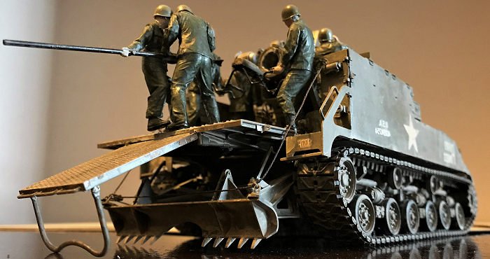
The final steps in the construction with the hull deals with the fighting compartment. The side walls, with four folded seats, spare ammo racks are made first. This is followed by the rear walls. Notice one side contains the winch that lowers or raises the dozer blade. Again, I saved this till much later. The construction of the dozer blade is next. I made it and allow it to swing freely until the end to attach the winch rope. Finally, the hull is complete with the attachment of the detachable floor boards. This is lowered when the cannon is prepped for firing but folded up when it’s traveling. You have to pick one. I picked the lowered fighting position since I will be making all eight figures but did not attach it until the end since it goes above the dozer blade. The hull is complete at this point.
The cannon construction begins with the cradle. Just becarefull with the hydraulic linkages G18 and G5. This quickly move on to the mount. Be sure not to cement part G29 to the mount.
The trunnions are next.
Poly caps are used to ensure the cannon can elevate. This is where the kits
biggest fault lies. You see, on the real thing, two large screws and nuts were
used to hold the trunnions together and allow it to elevate. This….This is where
I have to laugh at Tamiya sometimes cause sometimes they let Trumpeter’s “brain
gas” rub off on them off to
 the nadir or worse! Rather than mold the screw and
nut onto the kit, Tamiya decided to actually MAKE two 1/35 scale METAL nuts and
screws and have you actually try to SCREW the trunnions’ hydraulic linkages onto
the holders! Yes, a small plastic wrench with a socket is provided…But good luck
holding the nut with one hand, the screw with the other and a third and fourth
hand to turn the wrench!!!!! Even if you did have four hands, they are….well……A
freaking handful and a half! Took me 2 hours and more to finally get both on and
on one end, I messed up the hydraulic linkage so one side is more “retracted”
than the other. I didn’t bother to try to unscrew and then rescrew it again. Too
much of a headache! It would’ve been so much easier had Tamiya decided not to be
this cute! Remember all the magnets in their 1/32 Spitfire and Mustang
kits……..Yeah……
the nadir or worse! Rather than mold the screw and
nut onto the kit, Tamiya decided to actually MAKE two 1/35 scale METAL nuts and
screws and have you actually try to SCREW the trunnions’ hydraulic linkages onto
the holders! Yes, a small plastic wrench with a socket is provided…But good luck
holding the nut with one hand, the screw with the other and a third and fourth
hand to turn the wrench!!!!! Even if you did have four hands, they are….well……A
freaking handful and a half! Took me 2 hours and more to finally get both on and
on one end, I messed up the hydraulic linkage so one side is more “retracted”
than the other. I didn’t bother to try to unscrew and then rescrew it again. Too
much of a headache! It would’ve been so much easier had Tamiya decided not to be
this cute! Remember all the magnets in their 1/32 Spitfire and Mustang
kits……..Yeah……
After that PITA was over, all sorts of side attachments including the wheels that elevate or turn the gun, the aiming devices are attached. I saved the sighting units until later. The gun shields are then attached before the cannon assembly begins.
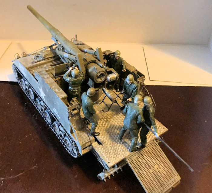
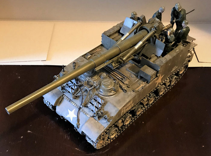
Again, the kit cannon barrel is in two pieces without any rifling. I bit the bullet and got Tamiya’s metal gun barrel. This is one piece turned aluminum with rifling. The breech is a multipart assembly. Study the instruction clearly since it can be build opened or closed. I opened it up since two of the figures are seen carrying a round to be rammed into the breech and two others are holding the rammer itself. The kit is mostly done at this point. I did not attach the cannon to the hull to ease painting. Time to hit the paint shop!
| COLORS & MARKINGS |
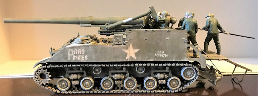
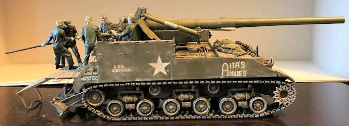
The overall paint again is Olive Drab and again, I used Testors. If you read any of my armor builds, you should know the routine now. Acrylic jet black wash, first layer of olive drab on. More black followed by another layer of olive drab. This time, I put on the markings….Which again, is generic and not a whole lot, especially compared to the AFV Club with 7, including both of the markings here, Courageous Confederate and Anita’s Ankies. AFV also contain the initial prototype sent to Germany and a British “Cardinal” version. So if you can get your hands on some spare AFV decals, I suggest you do so. For me? I just used the kits decals. I picked Anita’s Ankies. The decals went down nicely with Mr. Marks. These new generation Tamiya decals are a lot thinner than their previous ones. Which were so thick that without any decal softening agents, they will easily silver and not hold. They are also a lot tougher so they don’t just melt under Mr. Marks and actually dry out in less than two hours, rather than 24. After that, I slobbered the hull with artistic acrylic cream, beige, flat earth to denote dirt, mud and earth that got caught on the vehicle. Korea was a muddy mess sometimes and I wanted to show that. This goes throughout the vehicle all except the cannon itself. I would wager that every time this thing fires in anger, the massive recoil will shake all the dirt and mud right off the cannon itself! This is why the cannon is generally clean, all except the tip of the barrel, which is slightly darkened to denote it has seen action before. Ok, final assembly.
| FINAL CONSTRUCTION |
 The final bits are all the
pioneer tools first. These are colored and painted during painting and marking
session and put on the vehicle during weathering. This is followed by the lights
and the light guards and the tracks themselves, which were also assembled and
put on during painting and marking session to be weathered along with the rest
of the vehicle.
The final bits are all the
pioneer tools first. These are colored and painted during painting and marking
session and put on the vehicle during weathering. This is followed by the lights
and the light guards and the tracks themselves, which were also assembled and
put on during painting and marking session to be weathered along with the rest
of the vehicle.
The first big major assembly is the dozer winch. A thin twine is provided. I first assembled the winch wheel, and superglued one end of the twine there and then threaded the twine onto the winch wheel before attaching it to its housing assembly. I then poked the other end through the hole in the rear wall. Following the instruction carefully, there are two diagram here, one for the down dozer, the other for the up dozer. Following the down dozer diagram carefully, I threaded the twine through the correct roller wheel assembly before attaching the end onto the bottom of the blade itself, superglued permanently in place and cut off the excess. In order to keep the correct tight tension. I rolled the winch wheel tight, and then dropped a drop of superglue in place so the wheel will not “self-roll” and untighten the tension. This is a major assembly so take your time here cause you can easily goof if not careful. The floor boards, which I assembled down and unfolded, are now put in place since they go on top of the dozer. This and the rear compartment floor boards are heavily weathered to show the action going on in this place. No, not over yet.
The kit does come with all
eight figures used to operate the actual weapon. These consists of the
commander, the section chief, the fuse setter, the powder holder, two men who
carried the shell, and two men carrying a rammer to ram the round home. I
assembled each of them, have to be careful with the two men holding the tray to
ensure their arms are i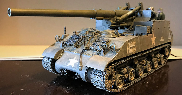 n the right place. Same with the rammers. Two of their
hands are molded onto the rammer itself. To make this easier, I superglued the
figure first onto the rammer, then assembled the rest so I don’t goof this up.
The figures are painted in medium green uniforms, leather belts, flesh faces and
hands, black tray and rammer and light grey powder bag. The extra shells are all
painted in olive drab, with decals on them along with flat black powder bag
holders. After they are done, the section chief, commander, the two loaders and
two rammers were positioned correctly onto the vehicle themselves, besides or
behind the main breech. The fuse setter and powder charge holder are positioned
below the vehicle, reading the next round and ready to load the powder charge
into the breech, with extra powder holders and rounds besides them. This creates
an interesting diorama and anyone who wants to build a fire base has everything
already in the bag to do so if wished.
n the right place. Same with the rammers. Two of their
hands are molded onto the rammer itself. To make this easier, I superglued the
figure first onto the rammer, then assembled the rest so I don’t goof this up.
The figures are painted in medium green uniforms, leather belts, flesh faces and
hands, black tray and rammer and light grey powder bag. The extra shells are all
painted in olive drab, with decals on them along with flat black powder bag
holders. After they are done, the section chief, commander, the two loaders and
two rammers were positioned correctly onto the vehicle themselves, besides or
behind the main breech. The fuse setter and powder charge holder are positioned
below the vehicle, reading the next round and ready to load the powder charge
into the breech, with extra powder holders and rounds besides them. This creates
an interesting diorama and anyone who wants to build a fire base has everything
already in the bag to do so if wished.
| CONCLUSIONS |
Again, this is another great kit from Tamiya, all the problems not withstanding…..Just wish they would stop borrowing Trumpeter “brain gas” that’s all and it is at the forefront of the fourth generation of Tamiya kits. It still offers Tamiya’s famed ease of assembly but contains enough details that it will turn out into a show stopper in the right hand, especially with the aftermarket metal barrel….Cash grab not withstanding! You can forgo the figures and just make the vehicle. Or make the figures and turn the piece into quite the diorama by just adding the base and the setting. All in all, this is a bargain at just $60 if you import directly from Japan!
1 July 2019
Copyright ModelingMadness.com
If you would like your product reviewed fairly and fairly quickly, please contact the editor or see other details in the Note to Contributors.
Back to the Main Page Back to the Review Index Page Back to the Previews Index Page