AFV Club 1/35 M110 8 inch SPG
| KIT #: | 35110 |
| PRICE: | $80.00 |
| DECALS: | Five options |
| REVIEWER: | Dave Cummings |
| NOTES: |
| HISTORY |
 (Summarized from the instruction
booklet) A need for self-propelled artillery manifested itself during WWII.
Earlier attempts consisted of mounting a gun on an existing tank chassis. The
weight of these systems hindered mobility and ability to be airlifted. In
January 1956 a requirement for a new reduced weight vehicle capable of mounting;
155, 175, and 203 mm guns was issued. By September of that year Pacific Car and
Foundry produced six prototypes for evaluation. To fulfill the requirement for
reduced weight the new design utilized an open fighting compartment. It was
constructed of welded aluminum plate and engineered to withstand the forces of
recoil. To facilitate stability during firing the suspension can be locked and a
large dozer type blade is used as a spade to absorb recoil. The new chassis
showed potential for development as an armored recovery vehicle and the M578 was
eventually developed from this program. In March 1961, the US military
officially selected the 175mm and 203mm versions and dubbed them the M107 and
M110 respectively. The 203mm (8inch) Howitzer has a firing range of 16.3
kilometers and is highly accurate. The gun can traverse 30 degrees from center
and utilizes a semi-automatic loading system. Both the 175 and 8inch guns are
capable of firing a nuclear projectile. Fielding began in 1963. M110s were
deployed to Vietnam beginning 1965. In 1977 M110s were upgraded to the
203mm/37calibre gun M110A1.
(Summarized from the instruction
booklet) A need for self-propelled artillery manifested itself during WWII.
Earlier attempts consisted of mounting a gun on an existing tank chassis. The
weight of these systems hindered mobility and ability to be airlifted. In
January 1956 a requirement for a new reduced weight vehicle capable of mounting;
155, 175, and 203 mm guns was issued. By September of that year Pacific Car and
Foundry produced six prototypes for evaluation. To fulfill the requirement for
reduced weight the new design utilized an open fighting compartment. It was
constructed of welded aluminum plate and engineered to withstand the forces of
recoil. To facilitate stability during firing the suspension can be locked and a
large dozer type blade is used as a spade to absorb recoil. The new chassis
showed potential for development as an armored recovery vehicle and the M578 was
eventually developed from this program. In March 1961, the US military
officially selected the 175mm and 203mm versions and dubbed them the M107 and
M110 respectively. The 203mm (8inch) Howitzer has a firing range of 16.3
kilometers and is highly accurate. The gun can traverse 30 degrees from center
and utilizes a semi-automatic loading system. Both the 175 and 8inch guns are
capable of firing a nuclear projectile. Fielding began in 1963. M110s were
deployed to Vietnam beginning 1965. In 1977 M110s were upgraded to the
203mm/37calibre gun M110A1.
| THE KIT |
I have built a few military vehicles over the years though my interest lies mainly in modeling aircraft. I wanted to build an M110 as a Xmas present for my brother-in-law who served on one in Germany in the 70s. He had a picture of his vehicle, so I decided to surprise him. In searching for a kit I found there were two choices available in 1/35 scale, Italiery and the more expensive AFV Club. Figuring you get what you pay for, I opted for the AFV kit and thus, the adventure begins.
Packed in a sturdy top opening box
are 16 (yes 16) sprues of OD plastic, 1 sprue of clear, a metal gun barrel, two
metal hydraulic sleeves, one photo etch fret, one viny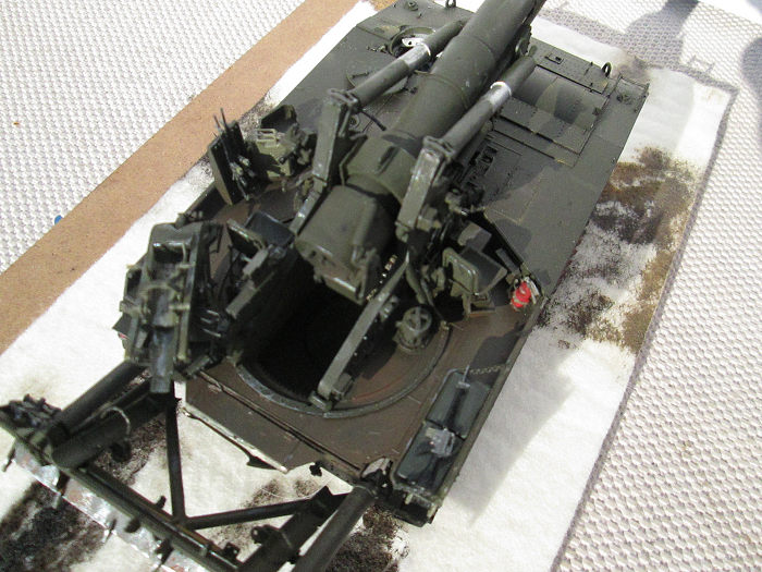 l sprue of flexible hoses,
vinyl tracks, a length of twine for cable, a decal sheet, and a 24-page
instruction book. It does appear a bit intimidating at first glance. Like it
would be helpful if you had tracked vehicle mechanic training. Looking over the
parts it is immediately apparent that the detail and overall quality of the
moldings is amazing. I mean there are sections of hydraulic lines not much
thicker than sewing thread molded in plastic. Each roadwheel is 5 parts
including those little vinyl inserts that press onto the axle and separate
rubber tire. Each gunner’s seat is comprised of 9 parts. Get the idea.
l sprue of flexible hoses,
vinyl tracks, a length of twine for cable, a decal sheet, and a 24-page
instruction book. It does appear a bit intimidating at first glance. Like it
would be helpful if you had tracked vehicle mechanic training. Looking over the
parts it is immediately apparent that the detail and overall quality of the
moldings is amazing. I mean there are sections of hydraulic lines not much
thicker than sewing thread molded in plastic. Each roadwheel is 5 parts
including those little vinyl inserts that press onto the axle and separate
rubber tire. Each gunner’s seat is comprised of 9 parts. Get the idea.
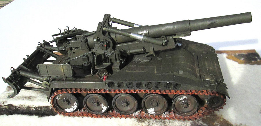
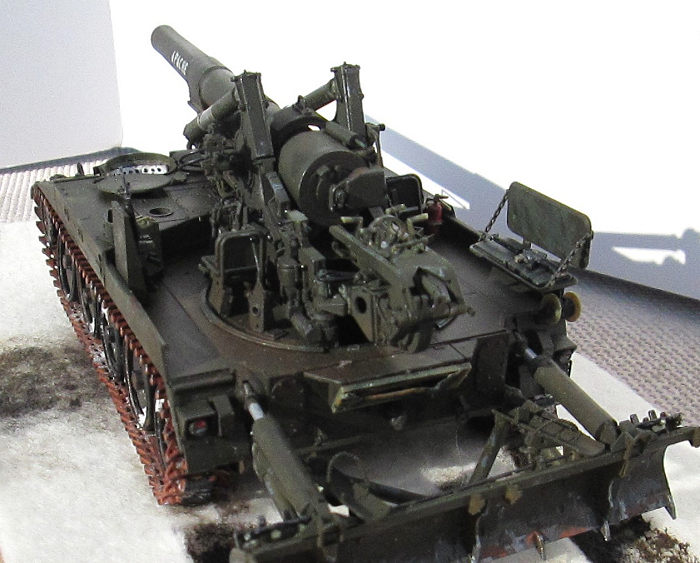
Operating features include: The gun traverses the correct 30 degrees, elevates, and will slide back in recoil position. The recoil spade raises and lowers. The auto loader rotates, the arms extend, and the projectile cradle swings and detaches as on the real deal. The hydraulic arms of each system slide in and out appropriately.
No figures are included nor artillery rounds. You do get a variety of small arms appropriate for the time period of each markings option, and a couple nicely done Jerry cans.
| CONSTRUCTION |
This proved to be quite a challenging build. Working here and there I took three months on this project. Now, unlike a tank, this SP gun has all its insides on the outside. Every lever, hydraulic line, and electrical cable. Steps 1-5 are the basic chassis and road wheels. The road wheels have those little vinyl inserts in the hubs and just press on to the axles. Since they are also easily removed, I didn’t attach the rubber tire rings yet to help painting. Step 6 is the driver’s compartment. The walls were painted white, and the 13 parts assembled when dry. There is an instrument panel decal. When gluing the compartment to the chassis make sure the top edge aligns with the chassis side or the top deck will not fit right (test fit, test fit). I had to do a little filing in places on mine. There are clear vision blocks to attach to the top deck as well some PE screens. Step 8 has you assemble the tracks, but I skipped this to facilitate painting. The next few steps proceeded uneventfully. The headlights are two pieces one clear. Paint the silver and red/black lights from the inside before assembling. I left off the pioneer tools until after painting, or you can just paint over them and come back later to detail paint them. After detailing the very nice headlight assemblies, I noticed in the photo of the subject I am building that it had no lights. Have to ask about that.
Steps 12-14 is the recoil spade assembly. The instructions are vague on just how to align parts K62 and 63. Fiddle with hem until it makes sense how they go. The hydraulic sliders that fit into the hydraulic cylinders are already attached to the chassis. I test fit the cylinders to these and found it was too tight. This will require too much force to be put on the flimsy plastic assembly to operate. I drilled out the cylinders with a 3/32nd bit allowing them to slide easily. Glue the outer hydraulic cylinder brackets parts K10 and 11 to the spade, let dry, place the cylinder ends over the pins, then glue the inner bracket halves being careful not to get glue on the pins leaving the cylinders free to swivel. The cylinder ends need to be filed down some as they wedge against the spade too tightly to pivot. Again, test fit.
 Step 15 shows attaching the spade
assembly to the chassis. I chose not to at this point. I did test fit though
which revealed the attachment points of the spade frame are too tight. These are
a simple press fit where raised dimples pop into shallow holes. Having already
dealt with the hydraulic assemblies, these fit together no problem. Had to thin
the frame arms by filing without erasing the little dimple-to-hole thing. So,
somewhat fiddly, but it works fine now.
Step 15 shows attaching the spade
assembly to the chassis. I chose not to at this point. I did test fit though
which revealed the attachment points of the spade frame are too tight. These are
a simple press fit where raised dimples pop into shallow holes. Having already
dealt with the hydraulic assemblies, these fit together no problem. Had to thin
the frame arms by filing without erasing the little dimple-to-hole thing. So,
somewhat fiddly, but it works fine now.
My plan was to build all the major sub-assemblies: chassis, spade, gun mount, and gun. At this point I did my painting of these assemblies and decaling. I then put everything together and began taking care of the little detail stuff. That’s the plan, so off to the gun mount next.
Steps 16-32 are the gun mount assembly and by far the most detailed. The gun cradle parts, E33 and 34, have a pin that needs cut off. These parts are also the only ones needing some filler and seam care in the whole project. Part E1 has cutouts to fit over alignment lugs on the cradle, but they won’t. Had to cut off these lugs for E1 to seat. The brass hydraulic cylinders glue to plastic swivel ends that are attached to the cradle by plastic pins, parts F25. Test fitting reveals a problem that is common to most operating parts, the fit tolerances are too tight to move easily. The holes in the swivel ends have to be routed out slightly. Be careful with the glue so these parts move freely. Step 22 is the slider to cylinder to cradle assembly. I left this off until after painting as paint can weld these parts together. I did not attach the cradle assembly to the mount until after painting.
Steps 23-28 will introduce you to the M sprue. This is all the hydraulic lines and electrical cables. Very petite moldings that require much care cutting from the sprue and clean up. Exact placement of some of these in the whole pile of spaghetti can be confusing in places. The drawings are well done though and if unclear on a part, look at the next step which will show that part in place.
Seps 34-35 are the gun tube. You have an option of breach open or closed. When assembled test fit gun to the cradle assembly. It is supposed to slide on, but as expected fit was too tight. Had to do some cutting and filing on the rails. Major issue here is the recoil tubes, part E35, insert into wells on the cradle. Again, too tight. Had to drill out these wells some.
Steps 36-38 are the auto-loader assembly. It is designed to show the functioning of this system. It rotates in and out of battery. The lifter arms unfold. The projectile cradle hooks onto these arms and will detach so you can carry a round from your ammo point to the gun. Pretty fiddly assembly. Study drawings carefully. PartK29 doesn’t fit how it seems to show. Again, test fit, test fit. Don’t attach the assembly until after painting.
Steps 40-44 are various detail parts which should go on before paining except for the rifles, fire extinguisher, and jerry cans.
| COLORS & MARKINGS |
 The model is molded in OD plastic
which tempts one to leave it that color. But its not the right shade of OD. I
first painted all the sub-assemblies Tamiya XF-62 Olive Drab. When dry, I mixed
up a thinned OD with some light gray to lighten it up. I sprayed this on
selected areas on the chassis top and the top side of the gun. I brush painted
some thinned red brown on the floor of the crew compartment, the chassis inside
the road wheels, areas on the road wheels , and on the rear spade to dirty thing
up a bit. I did some dry brushing on edges and such with some steel (silver is
too bright). I painted the sections of hydraulic sliders chrome silver. Exhaust
port screens got some flat black.
The model is molded in OD plastic
which tempts one to leave it that color. But its not the right shade of OD. I
first painted all the sub-assemblies Tamiya XF-62 Olive Drab. When dry, I mixed
up a thinned OD with some light gray to lighten it up. I sprayed this on
selected areas on the chassis top and the top side of the gun. I brush painted
some thinned red brown on the floor of the crew compartment, the chassis inside
the road wheels, areas on the road wheels , and on the rear spade to dirty thing
up a bit. I did some dry brushing on edges and such with some steel (silver is
too bright). I painted the sections of hydraulic sliders chrome silver. Exhaust
port screens got some flat black.
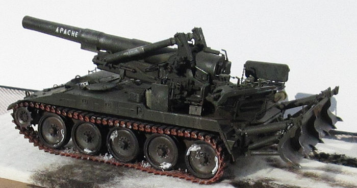
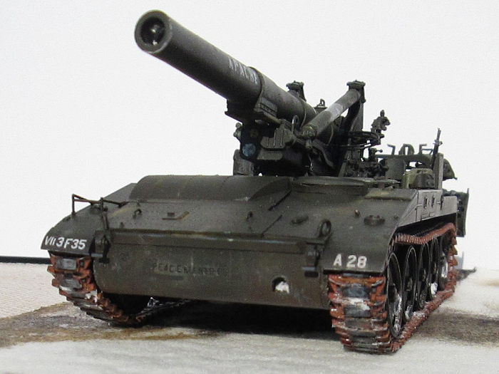
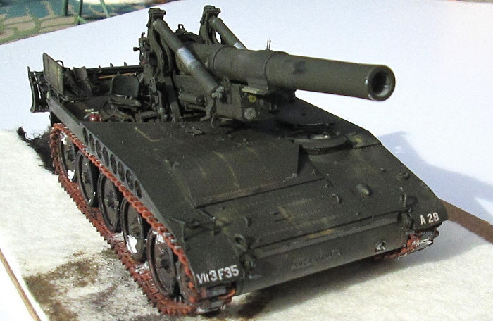
Next, I brushed on some acrylic clear gloss in the areas to be decaled. Obviously, there is no decal set for this vehicle. Luckily, I was able to cut and paste the APACHE from the kit decal sheet. I then went about cutting up individual numbers and letters for the bumper number and unit designation. A search through my decal dungeon turned up the missing digits. I was also able to piece together black PEACEMAKER logo on the front.
After allowing the paint to cure I applied a black acrylic wash around engine covers and such. I used some tan and light brown pastels applied with cotton swabs or finger to further dirty things up. But I didn’t over do it. When finished I gave everything a coat of Testor’s Dullcoat flat.
| FINAL CONSTRUCTION |
 Next was to put all the
sub-assemblies together. I snapped on the spade assembly that I had filed to fit
previously. The gun was slid onto the cradle rails and pushed all the way
forward. At this time the gun hydraulic arms were assembled. I had previously
insured their fit but the coat of silver on the sliders had taken up that
tolerance and the slider was just a wee bit sticky. I applied a few drops of
mineral oil (baby oil) to the sliders, and it works smoothly now.
Next was to put all the
sub-assemblies together. I snapped on the spade assembly that I had filed to fit
previously. The gun was slid onto the cradle rails and pushed all the way
forward. At this time the gun hydraulic arms were assembled. I had previously
insured their fit but the coat of silver on the sliders had taken up that
tolerance and the slider was just a wee bit sticky. I applied a few drops of
mineral oil (baby oil) to the sliders, and it works smoothly now.
The completed gun mount assembly
was inserted into the chassis. There two tabs to be inserted into slots on the
chassis. The gun is supposed to traverse the correct 30 degrees right and left.
Test fitting earlier had revealed a snug fit, but not too bad. Now I found that
it took too much pressure to operate risking damage to the model. I decided to
just glue it in place so one wouldn’t be tempted to try it. Wasn’t about to tear
things apart to try and fix it. In the end, all turned out well.
March 2023
Copyright ModelingMadness.com. All rights reserved. No reproduction in part or in whole without express permission.
If you would like your product reviewed fairly and fairly quickly, please contact the editor or see other details in the Note to Contributors.