Lindberg 1/390 Q-Ship
| KIT #: | HL400/12 |
| PRICE: | $10.00 'used' |
| DECALS: | One option |
| REVIEWER: | George Oh |
| NOTES: | An ancient kit that needed the PE bits. |
| HISTORY |
A ship is a large piece of equipment. Some are VERY large. So large are they, that they are hard to hide, especially when they are sailing along on top of a calm sea in broad daylight. And they are dangerous too, because enemy submarines like to sink them with cannon-fire or torpedoes. A submariner observing an enemy ship through a periscope, would have to accurately estimate its size, speed, course and heading, then correctly position the submarine to launch a torpedo so that both would arrive at the same place at the same time. This hit would allow the torpedo to explode against the side of the ship, and possibly sink it. BEFORE the advent of radar and laser range-finders, only a very-skilled submarine commander could come up with these accurate estimations from his observations and the aids attached to his periscope.
So how do you hide a ship from an enemy submarine? You
can’t, because they’re large, and are often silhouetted on a horizon, against
the (often brighter) sky. Instead, a way was developed that would cause the
enemy submariner quite some difficulty in estimating the ship’s size, speed,
course and heading, which then made the rest of the correct requirements for a
successful torpedo attack, equally difficult. The
 mechanism was
to paint the vertical surfaces of the ship with contrasting stripes and patterns
– usually using black and white, but other colours could be added as well.
Several experts in the USA and Great Britain, lay claim to developing this
dazzle camouflage (known as Razzle Dazzle in the USA). Dazzle patterns were not
standardized, being dependent on the ship being painted, the painters, and
possibly the ship’s captain as well.
mechanism was
to paint the vertical surfaces of the ship with contrasting stripes and patterns
– usually using black and white, but other colours could be added as well.
Several experts in the USA and Great Britain, lay claim to developing this
dazzle camouflage (known as Razzle Dazzle in the USA). Dazzle patterns were not
standardized, being dependent on the ship being painted, the painters, and
possibly the ship’s captain as well.
Dazzle Cam was supposed to work because the range-finding optics of that time utilised a (vertically or horizontally) split screen. As the observer viewed the target, its two halves would be displaced from each other across both halves of the split screen. The observer then rotated a knob/wheel till the two halves of the target aligned with each other, then he read-off the range. But the dazzle cam made aligning the halves quite difficult. Additionally, the demarcations in the dazzle cam could also make equally difficult, identifying which end of the ship was the bow (or stern), or even what type of ship it was.
Did it work? Statistics are inconclusive, but in the words of an un-named U-Boat Kaptain “It was not until she was within half a mile that I could make out she was one ship (not several) steering a course at right angles, crossing from starboard to port. The dark painted stripes on her after part made her stern appear her bow, and a broad cut of green paint amidships looked like a patch of water. The weather was bright and visibility good. This was the best camouflage I have ever seen.”
| THE KIT |
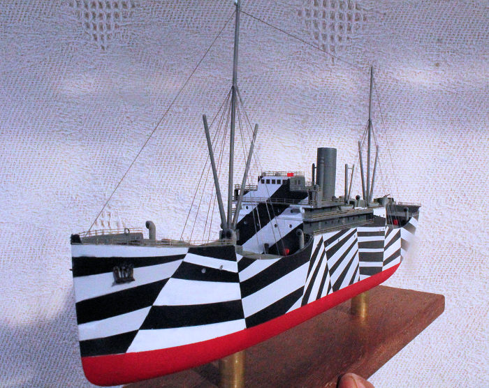
This is an ancient Lindberg kit of a small ‘tramp’ steamer or coastal freighter. Initially, it was released as a toy (the flat bottom reveals that), then as a motorised toy (kit parts not mentioned in the instructions reveal that). The box is a long tray with a hinged-lid, and the instructions are printed on a double-sided A3-sheet with six assembly diagrams and a rigging & decaling diagram. The small decal sheet provides a red band for the funnel, a US-style bow number, and decals for the portholes, air intakes (several sizes of) and the bridge windows.
 Its 41
light-grey parts, including a 4-part stand, are moulded in soft light-grey
plastic. The hull is split laterally, and the deck is a single piece. Detail is
brilliant in some areas (like the engraved deck), and poor in others (ship’s
boats, winch drums). Much of the detail is of the raised panel line variety
(port-holes, chains and anchors) or moulded as items embedded into the deck (the
winch and anchor drums). Included, but not mentioned in the instructions, are a
few parts left-over from its former motorised days. My biggest gripe was with
the railings. They were moulded as solid walls with a narrow A-shaped
cross-section (probably to assist the extraction of the parts from the moulds).
In some places, they came really close to the walls of the superstructure.
Its 41
light-grey parts, including a 4-part stand, are moulded in soft light-grey
plastic. The hull is split laterally, and the deck is a single piece. Detail is
brilliant in some areas (like the engraved deck), and poor in others (ship’s
boats, winch drums). Much of the detail is of the raised panel line variety
(port-holes, chains and anchors) or moulded as items embedded into the deck (the
winch and anchor drums). Included, but not mentioned in the instructions, are a
few parts left-over from its former motorised days. My biggest gripe was with
the railings. They were moulded as solid walls with a narrow A-shaped
cross-section (probably to assist the extraction of the parts from the moulds).
In some places, they came really close to the walls of the superstructure.
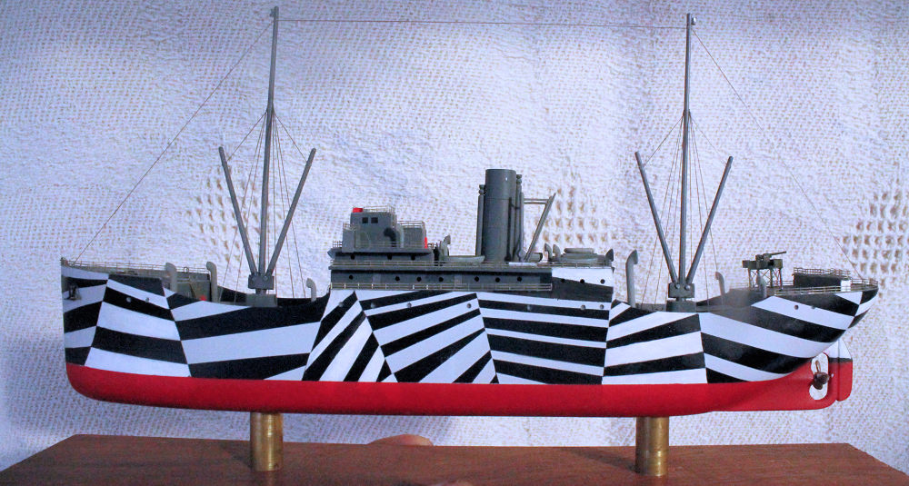
I bought this model because I found it in its iteration as a Q-Ship (which is an unusual subject) for $10-00 (which is an unusually-low number). I started it because our Modelling Club (WAPM) elected to do a 2018 Club Display entitled “Stripes” This was the perfect reason for me to do this model in a dazzle-cam pattern, because I always wanted to do a ship in this patterning. That, and the fact that, in a photo I found on the Internet, the small tramp freighter being painted in dazzle-cam looks amazingly like the Lindberg Q-Ship. Do all small coastal/tramp freighters look the same?
| CONSTRUCTION |
I targeted ten things for improvement and tackled only eight. The engraved cargo hatch covers will have to be replaced with something more 3D. The existing portholes will have to be drilled-out, and more will have to be added as per the boxart. Watertight doors are needed as there are none anywhere. Narrow walkways around structures will have to be widened by reducing the structures that obstruct them. Some solid structures will have to be reduced or removed. The solid railings will have to go, and be replaced by PE. The anchors and chains will have to be replaced by something thicker than an engraving. The anchor and crane winches will have to be chiselled off from the deck and replaced with something more 3D. And even a cammed ship should have some sort of pop-gun for self-protection (besides, I wanted it to have one). I ordered the required PE bits from my local internet hobby store (BNA), and received them in four days (including a weekend and a public holiday – THAT is service).
My ‘Bridge Too Far’ was a raised gantry across the stern/poop deck that is used to dis/embark crew and/or passengers. This was cast atop a solid block that effectively divides the poop deck. I would have liked to remove it, but it was cast hollow underneath, and its complicated shape precludes me from replacing the block with scratch-built latticework. So I’ll have to live with it in its solid form (Rats!).
 Construction
started by gluing the hull halves together. Fit was good, but I still reinforced
the fore/aft join with strips of plastic inside the hull. Because I don’t yet
know if I’ll mount this model on pedestals or place it in ‘water’, I epoxyed
nuts to the bottom of the hull (inside) to accept bolts at a later date.
Construction
started by gluing the hull halves together. Fit was good, but I still reinforced
the fore/aft join with strips of plastic inside the hull. Because I don’t yet
know if I’ll mount this model on pedestals or place it in ‘water’, I epoxyed
nuts to the bottom of the hull (inside) to accept bolts at a later date.
Meanwhile, I cut eight squares from 0.75mm plastic card to replicate the raised hatches over the cargo holds. For you landlubbers, if the hatches were flush with the deck, as engraved, water flowing across the deck just might enter a hold, and wet the cargo. All railing bits were excised by scribing along their bases, parallel to the deck. I was not 100% successful at this and had to glue a couple of edge-repair strips along a couple of decks (and perform the required filling with Tamiya white putty). After trimming the excessive bits off the superstructure (and filling the exposed void/s with plastic card and filler), the layers up to the bridge were glued on, and they fit together nicely.
Portholes were drilled as dimples everywhere that they were shown on the boxart. They were only dimples for now. I’d complete the drilling after all of the painting was done. I filled a couple of lifeboat locating holes because some brilliant marine engineer placed the two largest ones smack-bang in the middle of a walkway. Watertight doors went on where I’d left room for them, then the deck was attached to the hull. The only deviation from the instructions was that the boat deck was supposed to go BETWEEN the hull halves. That would have left a step between the deck and the hull. To eliminate the step, I put the boat deck ON TOP of the hull halves, and anyway, the boxart showed it that way.
| COLORS & MARKINGS |
While the basic assembly was underway, I got ahead of the game by spraying the hull, and the other vertical surfaces that needed it, with several coats of Citadel Miniatures skull white (from a rattlecan). This let me mask (over several sessions in a week) the bits that needed to be preserved in white. A coat of black followed, with the masking being removed immediately after spraying. Some days later, the bottom of the hull was masked and sprayed a faded matt red.
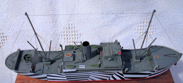
 I
tossed-around a few colours to paint the deck, and finally settled on a
nondescript dark grey. It also went on to the ship’s inner vertical surfaces
(hull and superstructure). Areas of the deck were picked-out and dry-brushed in
different shades of grey to avoid a monochrome appearance. With all of the big
bits painted, the deck was stitch-glued to the hull to ensure a proper fit. Yay
me!!! Naturally, there were areas of poor fit, and they needed filling and
touch-up painting.
I
tossed-around a few colours to paint the deck, and finally settled on a
nondescript dark grey. It also went on to the ship’s inner vertical surfaces
(hull and superstructure). Areas of the deck were picked-out and dry-brushed in
different shades of grey to avoid a monochrome appearance. With all of the big
bits painted, the deck was stitch-glued to the hull to ensure a proper fit. Yay
me!!! Naturally, there were areas of poor fit, and they needed filling and
touch-up painting.
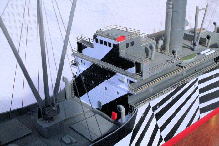
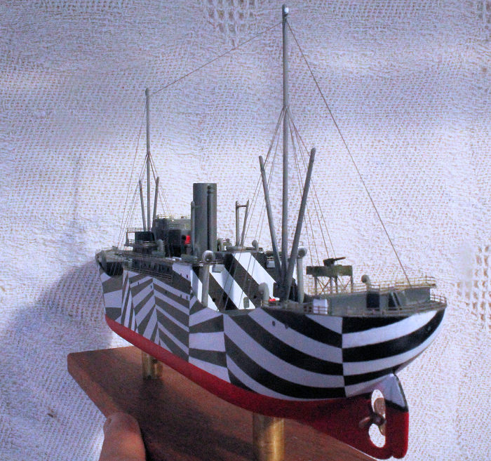
After another look at my reference photos, I had to back-track a bit to paint the fore and aft faces of the superstructure in dazzle-cam too. I had to make-up the pattern on the aft face as I didn’t have a reference for it. Because some black has seeped under the masks in a few places (Double Rats!!), I was forced to repaint several panels in white. Doing this with a brush imparted a brighter hue of white to those panels. Fortunately, the brighter fields appear to be in different planes from the other panels, and is in keeping with other photos of other ships in dazzle-cam. Yay me!! But it meant that I had to brush-paint ALL white stripes of a panel – not just the ones marred by that seeping black paint.
| MORE CONSTRUCTION |
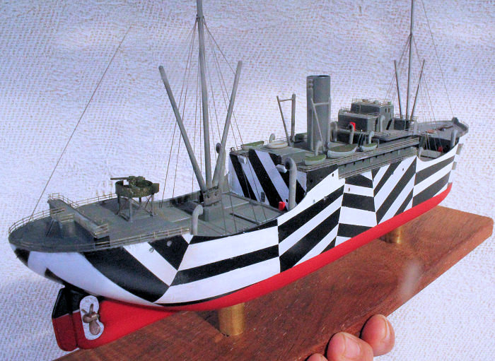
One of my ‘must-haves’ on this ship was a cannon. But where to put it? Against the railing at the back-end of the stern’s poop deck would be ideal (wide field-of-fire, stern-chaser gun – that sort of tactical detail) but a rigging line anchors there, and the raised gantry was right in the way. Now, as a Q-Ship, the ‘marine engineer’ has placed the cannon (concealed by a box-structure) on the forward edge of the poop deck. But the box is immediately above, and so it blocks-off, a set of access stairs/ladder – and the gun’s field of fire astern is still blocked by that dis/embarking gantry. My solution (and that of the Royal Navy) was to build an elevated gun tub above the locating square where the box should have gone. This gives the gun a brilliant field of fire to the sides and astern, it would fire over the raised gantry, AND it does not block the stairs.
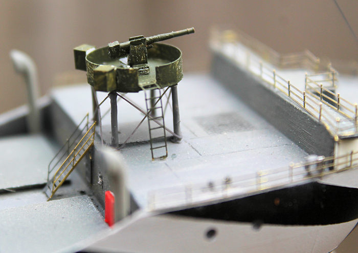 First, I
built my gun. Its core was a 105mm (I would have preferred a 75mm) brass barrel
taken from a set for a 1/400-scale Tirpitz (but that is another story – for
later. MUCH later.) A bit of wire underneath it replicates the recoil mechanism
(should it have been on top?). A small bit of plastic on the back will do for
the breech block, and a U-Shaped piece of thin card on a piece of strip will do
for the gun cradle. The gun tells me how big the gun tub will have to be. A
narrow length of thin plastic card was dragged across a steel ruler to curl it,
and then it was trimmed to form a C-Shape. This was attached to a 12mm circle of
card to make the tub, and it is shallow enough for the gun to be able to fire at
a slightly depressed angle (‘cos, personally, I’d HATE to be UNable to fire back
at an attacker because it was too close). To solidly anchor the gun tub’s
supports, I glued two 2mm-thick pieces of plastic card to the underside of the
deck, under the locating square. Craft wire was drilled vertically into them,
and trimmed to height, then X-shaped support bars (elastic EZ-Line, actually)
were superglued between them to provide the apparent support. The gun in its tub
was added towards the end of the build. The final bit was a piece of ladder to
allow the gun crew to access their gun, and two blocks of plastic simulate the
ready-use ammo boxes. I was considering making one from a piece of folded metal
foil, and have the lid open, but I couldn’t justify that for an unmanned gun.
First, I
built my gun. Its core was a 105mm (I would have preferred a 75mm) brass barrel
taken from a set for a 1/400-scale Tirpitz (but that is another story – for
later. MUCH later.) A bit of wire underneath it replicates the recoil mechanism
(should it have been on top?). A small bit of plastic on the back will do for
the breech block, and a U-Shaped piece of thin card on a piece of strip will do
for the gun cradle. The gun tells me how big the gun tub will have to be. A
narrow length of thin plastic card was dragged across a steel ruler to curl it,
and then it was trimmed to form a C-Shape. This was attached to a 12mm circle of
card to make the tub, and it is shallow enough for the gun to be able to fire at
a slightly depressed angle (‘cos, personally, I’d HATE to be UNable to fire back
at an attacker because it was too close). To solidly anchor the gun tub’s
supports, I glued two 2mm-thick pieces of plastic card to the underside of the
deck, under the locating square. Craft wire was drilled vertically into them,
and trimmed to height, then X-shaped support bars (elastic EZ-Line, actually)
were superglued between them to provide the apparent support. The gun in its tub
was added towards the end of the build. The final bit was a piece of ladder to
allow the gun crew to access their gun, and two blocks of plastic simulate the
ready-use ammo boxes. I was considering making one from a piece of folded metal
foil, and have the lid open, but I couldn’t justify that for an unmanned gun.
I discovered a small problem as I dry-fit some detail parts. The placing of the lifeboats (there are six of them) is problematic for the crew. The marine engineer has placed the two largest ones in the middle of a walkway where they would be a major inconvenience to the crew, and are inaccessible to the boat-launching crane. I really don’t know if this placing is correct, but it seems illogical to me. So I filled the holes with putty and left walkway clear. I was OK with the two medium and small lifeboats being placed on the boat deck, astern of the bridge. But they project outboard enough to occupy the same line as the perimeter railing. Again, I filled the holes with stretched sprue & card. Instead, all five boats (I’ve lost a large one) were repositioned along the inside the outer edge of the boat deck, and just far enough inboard so that someone could walk around the lifeboat (to inspect it?). While I was at it, I sat a boat cradle (of sorts) made of scrap plastic card where the missing boat should have been. The boat-launching cranes had to be repositioned so that they could reach all of the boats, and the largest lifeboat was placed in the centre, in front of it, to lessen the strain on the crane. The cranes were detailed with a crank/hand-wheel, but not ‘cables’ as replacing the moulded-on ones would have weakened the kit parts. Honestly, I had intended to scrape-off the embedded winches and replace them with PE, later, but dedication and a lack of knowledge beat me. (Rats and Double Rats!!!)
Did I mention that there are no decals in the kit for me to use to stuff-up my build? Then I discovered that I had to use decals to replicate the bridge windows and the mouths of the air intakes. The only problem was that the carrier film was wider than the air intake funnels, so they had to be trimmed.
All of the numerous detail bits were added, interspersed with the bouts of attaching 400-scale Aber PE railing and PE watertight doors and hatches in (hopefully) logical places. The railing is 3-bar with free-floating stanchion attachment points. Fortunately (for me) they are too tall for the decks of the deckhouse. So, by clipping-off the hanging part of each stanchion, I converted them from into two-rail fences, with a bottom rail by-which I could attach it to the deck (with superglue) – much easier, AND is resembles the boxart. Yay me, again!! Some of the stanchions had to be extended upwards to meet the upper deck (internet photos showed me that) but I took the cowards way out and used thin foil instead. I only wish that the paint would have stuck to the PE better than it did. (Double DOUBLE Rats!!!!
 The cargo
cranes were detailed with pivot pins (trunions?) for the crane arms, glued in
place, and rigged with stays (as per the instructions). Fine black EZ-Line (a
thin elastic ribbon) was my material of choice. To keep it from pulling the
masts together, I drilled holes through them, then threaded the line through
holes and didn’t glue it to them. Neither did I add the mast-to-funnel line
because I dunno that the cranes could have un/loaded cargo easily with all those
stays/lines in the way, but who am I to argue with the marine engineer?
The cargo
cranes were detailed with pivot pins (trunions?) for the crane arms, glued in
place, and rigged with stays (as per the instructions). Fine black EZ-Line (a
thin elastic ribbon) was my material of choice. To keep it from pulling the
masts together, I drilled holes through them, then threaded the line through
holes and didn’t glue it to them. Neither did I add the mast-to-funnel line
because I dunno that the cranes could have un/loaded cargo easily with all those
stays/lines in the way, but who am I to argue with the marine engineer?
More PE details, like stairs, were added where the moulded-on ones were excised off from the model (I left a few in-place). I reckon that I was supposed turn the treads of the stairs so they are flat, but this is my first real PE, so I’ll beg-off from THAT little job. Some vertical ladders were added where I thought they should go, and where I had excised-off moulded-on ones. But I left them off the bluff face of the superstructure because there was no way to safely open (or close) a door while standing on the top of that ladder. Besides – I was working to a deadline. Finally, I laid the anchor chains between their winches (which I didn’t replace) and their hawse pipes (which I had to drill-out), and attached two small Flyhawk 350-scale PE anchors to their positions on the bow. They certainly DO look much better than the ones that were engraved there.
Admittedly, attaching the railings and doing the rigging was harder than writing about it, but if you do just one bit at a time (like building a model in sub-assemblies), it is less-intimidating than looking at it as one HUGE project. But, yes, at an early stage, you DO have to view the whole project so that you can plan the work so that you are NOT trying to do a later bit when there is an earlier bit in the way.
Now, I coulda’ declared this one finished, but I always consider my workers, and you KNOW that I am a rather finicky modeller (sometimes). So, I added some ‘lights’ – mast-head lights, lights to illuminate both well decks (where the cargo hatches are), and a small searchlight in front of each bridge wing. I added other work lights on top of the crane jibs, and I replaced the moulded-on port-&-starboard light boards with ones folded from thin metal foil. A 2-part ships fog-horn was added atop the bridge, and steam sirens(?) on the funnel were painted brass. For a splash of colour, red (fire hose?) boxes and hydrants were sprinkled around the ship. Once I discovered that they were invented in 1903, I added two scratch-built Carley floats to the ship in various places – a large one from bent plastic rod and a small one from solder. This led me to add like-preserver rings (cut from small-diameter plastic tube) around the ship, as well. As I was a soldier (not a sailor), I couldn’t think of anything else to add, so I called it quits – that is, till a fellow modeller pointed-out that I’d not yet added the ships propeller. I told him that I DELIBERATELY left it off till the last second so that I could handle the model by its forefoot and the rudder.
| CONCLUSIONS |
Well now I have a ship in bold dazzle cam, and I’ve made my first steps into PE’ing a ship model. I’ll decide later, if I want to mount it on a couple of pedestals or put it onto a water base. If I do the sea thing, then I’ll have to populate it with some crew figures (and a gun crew?). One thing I realise (now) is that I haven’t named her.
I dare-say that even a young modeller could assemble this kit into a ship-shaped model. Probably, a ship modeller (who might probably recoil at the flat bottom of the hull and consider waterlining it) could do a bang-up job on this kit and turn it into a highly-detailed work of art. Either way, I’m happy to recommend it to all levels of modeller.
| REFERENCES |
Just the instructions, internet photos and the boxart.
5 June 2018
Copyright ModelingMadness.com
If you would like your product reviewed fairly and fairly quickly, please contact the editor or see other details in the Note to Contributors.
Back to the Main Page Back to the Review Index Page Back to the Previews Index Page