| KIT #: | ?64006 |
| PRICE: | $99.00 |
| DECALS: | Four options |
| REVIEWER: | John Summerford |
| NOTES: | From the Maschinen Krieger line |
| HISTORY |
A description of whatever this model is, and the backstory can be found here.
| THE KIT |
Inside a largish box are three bags of sprues. The top bag holds the large white body parts and a smaller bag of vinyl cord and lengths of steel music wire. The second bag holds the clear, smoke-tinted windshield. Contained in the third bag are four white styrene sprues, three for the Camel and one for the driver figure. Two sprues of dark gray detail parts and two sprues of black vinyl with a satin patina also fill the bag. Total parts count (excluding spares) is 215 No flash is present in this example and the mold seams are discrete.
 A single
sheet printed on both sides and folded four times to create 10 panels holds the
instructions. The first panel is the cover and includes a symbol key and paint
chart. Colors are cited for Aqueous Hobby Color and Mr. Color. Kanji and English
descriptions are also included. Panel 2 has the parts map. The next two panels
cover the construction of the legs through nine steps. The next four and a-half
panels illustrate how to build the interior of the body and cockpit over 11
steps. Assembly of the figure and seat, plus their installation are covered in
the following four steps. Final assembly is done in step 28.
A single
sheet printed on both sides and folded four times to create 10 panels holds the
instructions. The first panel is the cover and includes a symbol key and paint
chart. Colors are cited for Aqueous Hobby Color and Mr. Color. Kanji and English
descriptions are also included. Panel 2 has the parts map. The next two panels
cover the construction of the legs through nine steps. The next four and a-half
panels illustrate how to build the interior of the body and cockpit over 11
steps. Assembly of the figure and seat, plus their installation are covered in
the following four steps. Final assembly is done in step 28.
Diagrams indicate that the leg parts are assembled by press fitting. There are a lot of no-glue icons present, meaning that the legs articulate. They also are built up in left and right sub-assemblies, so it is important to keep track of everything as the build progresses.
A separate card holds paint and decal instructions. Unfortunately, it’s printed in gray scale on sandy-yellow colored stock, just like the box. Three options are for different regiments: 1) 320th Armed Regiment, S Company in a two-tone gray over white scheme, 2) 7th Yeomanry Regiment, 3rd Ground Attack Company in a dark mottle over mid gray with a blue collar on the body, 3) 101st Regimental Space Combat Team in white. The fourth option is for the 2nd Flight Test Squadron with a three-tone mottle and red collar scheme.
| CONSTRUCTION |
Being unfamiliar with this type of kit, it was a bit of a challenge for me, so after examining the diagrams, I decided to employ Tom Cleaver’s strategy and follow the instructions. They start off slowly by putting together two subassemblies of the hip joints of the legs. These are put aside and brought back in step 9. I found this to be a good introduction as to how this kit is designed and the build process, including how closely the diagrams need to be followed. The fit of the parts is very good and one could skip cleaning up the seams of the mating surface if one so chooses. I did not which slowed the process down.
 It's
important to keep track of the left and right subassemblies and which side faces
forward. It wasn’t immediately clear to me how some of the moving parts are
internally mounted and where to not apply glue, but the diagrams gave me enough
clues.
It's
important to keep track of the left and right subassemblies and which side faces
forward. It wasn’t immediately clear to me how some of the moving parts are
internally mounted and where to not apply glue, but the diagrams gave me enough
clues.
The sequence moves down to the foot plates, (no, I didn’t hum the leg bone song to myself) and then doubles back to (what I think of as) the lower thigh. Employing a slow pace by constantly double checking each move and testing how the joints articulate, I spent nearly six hours assembling the pair. I skipped adding the hydraulic tubing until post painting assembly.
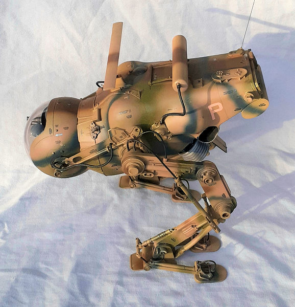
In contrast to the legs, assembling the Burner Nozzle and main body needed about two hours less time, including waiting for paint to dry. Again, fit of the parts was very good. However, after a little bit of seam clean-up, the addition of the additional equipment, except for the antenna (thingy?) to the various places on the body extended the build time beyond the legs. The collar was added at this time instead as called for in the final assembly. The body was put aside for later painting.
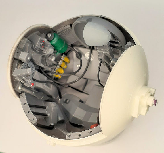
I became confused when I
examined the orthographic projections of the cockpit in Step 18. They highlight
the length and attachments of the various bits of hose. The drawings also
indicate where the styrene parts go, as do later steps drawn in isometric view.
I moved onto Step 19 and glued the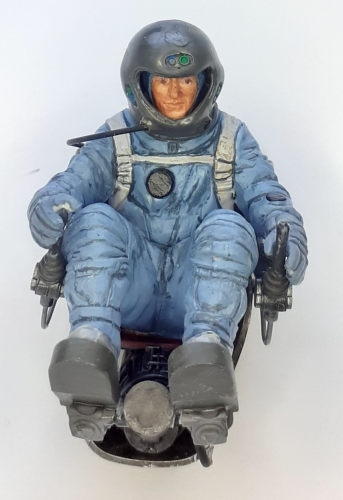 halves together, then installed the rear piece. The next two steps direct the
installation of right and left sides of the cockpit. The only color call-outs
are for the overall cockpit dark gray. I arbitrarily painted various components
different colors to add more interest. When I added the hoses, I referred back
to the drawings in Step 18. The process reminded me of rigging a biplane. By
adding the collar to the body earlier, I discovered that it simplified the build
considerably by hiding a lot of the hoses, so those were skipped.
halves together, then installed the rear piece. The next two steps direct the
installation of right and left sides of the cockpit. The only color call-outs
are for the overall cockpit dark gray. I arbitrarily painted various components
different colors to add more interest. When I added the hoses, I referred back
to the drawings in Step 18. The process reminded me of rigging a biplane. By
adding the collar to the body earlier, I discovered that it simplified the build
considerably by hiding a lot of the hoses, so those were skipped.
After the seat was built up, it was test fitted into the back of the cockpit to discover where the glue points were, then set aside for the pilot (or is it an operator?) figure. This is where figure modelers can have fun assembling and painting. The color call-outs are for mixes of paints. I ignored them and devised my own color scheme. The pilot/operator was glued to the seat. Once again test fitting was done to devise a method of maneuvering the assembly and gluing it in place. There are not any positive locating points, so epoxy was slathered in several areas and the assembly was twisted into place.
The clear windshield was masked and glued into place. Hexagonal detail bits were attached and the articulating breach of the laser gun added and the major assemblies were ready for paint.
| COLORS & MARKINGS |
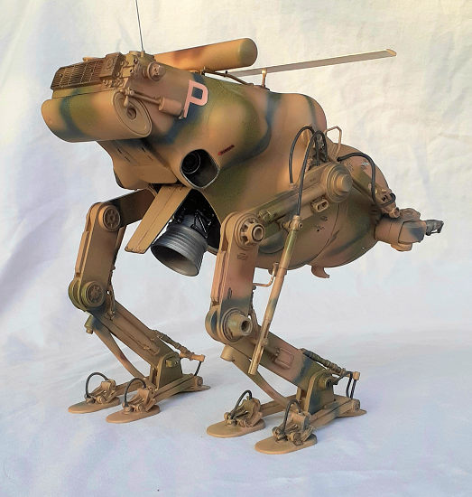
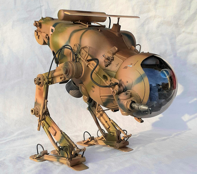
 According
to the storyline on the box lid, the Camels were first used for combat on the
Moon. I imagined their use on Earth and conceived a terrestrial camouflage
pattern.
According
to the storyline on the box lid, the Camels were first used for combat on the
Moon. I imagined their use on Earth and conceived a terrestrial camouflage
pattern.
An experiment regarding Alclad’s clear primer was done on the windshield. After that had cured, the cockpit gray was sprayed on the frame. The other parts were coated with MRP’s tan primer. My color scheme, uses Israel Khaki, British Dark Slate Grey, Swedish Army Dark Blue, German RLM 70 (gray-green), and, I think, Italian Brown. (The name of the paint had rubbed off the label.)
After two gloss coats, decals from the kit’s sheet were applied. Apart from the two “P”s, all of the decals are stencils, which made for several sessions of working around the model. I decided that the supplied “RESCUE” arrows for the canopy are too large and garish for the camouflage scheme, so I used a pair from the decal dungeon.
A couple of flat coats removed the gloss sheen and the better part of day was spent brushing on washes and rubbing on powders to bring out detail and giving a slight worn look. Unmasking revealed that the clear primer worked very well.
| FINAL CONSTRUCTION |
 Before
installing the hydraulic tubing on the legs, each piece was rubbed with dark
gray powder to take the sheen off surfaces. Gluing the tubes in place proved to
be straight forward. When the glue had set, the legs were pressed in placed. I’m
not sure that I got them securely attached, being as I didn’t get the positive
indication that I observed with the other parts that were pressed fit. The right
leg has a bit of a wobble at the hip but not enough to warrant glue. As oppose
to the legs, the cockpit just popped into place.
Before
installing the hydraulic tubing on the legs, each piece was rubbed with dark
gray powder to take the sheen off surfaces. Gluing the tubes in place proved to
be straight forward. When the glue had set, the legs were pressed in placed. I’m
not sure that I got them securely attached, being as I didn’t get the positive
indication that I observed with the other parts that were pressed fit. The right
leg has a bit of a wobble at the hip but not enough to warrant glue. As oppose
to the legs, the cockpit just popped into place.
The big event was to stand the model on its feet. I’m glad that I could articulate the legs because I had to adjust them a couple of times before I could get it to stand up. It seems to me that the model is nose heavy, so I’m a bit amused to suggest that perhaps 10 to 15 grams of ballast be added to aft end of the body.
Only three styrene pieces were left to be added, some type of bar on the underside, (again, an antenna of some sort?) and the afore mentioned antenna thingy on the top. The final piece was the laser gun barrel.
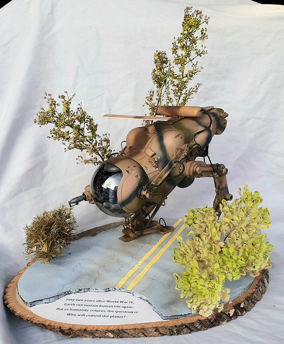
Fifty two years after World War IV
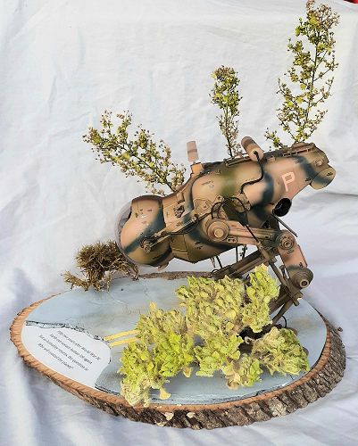 In order to
add some context for those not familiar with LUM-168 Camels, such as yours
truly, I created a vignette of it walking on a deteriorating, post-apocalyptic
road. The base is an ovoid cross section cut from a basswood tree, complete with
the bark. The road is 220 grit sandpaper laminated to black foam board and a
section removed for the label. The sandpaper was sprayed with rattle can black
and gray. Faded yellow stripes were applied, then everything rubbed with various
powders. The cracks were cut in by a hobby knife. (Yes, it caused havoc with the
blade.) I’m pleased with how well that worked. The label was glued to the base.
It reads: “Fifty two years after World War IV, Earth
can sustain human life again. But as humanity returns, the question is: Who will
control the planet? “ The road was laminated on
next.
In order to
add some context for those not familiar with LUM-168 Camels, such as yours
truly, I created a vignette of it walking on a deteriorating, post-apocalyptic
road. The base is an ovoid cross section cut from a basswood tree, complete with
the bark. The road is 220 grit sandpaper laminated to black foam board and a
section removed for the label. The sandpaper was sprayed with rattle can black
and gray. Faded yellow stripes were applied, then everything rubbed with various
powders. The cracks were cut in by a hobby knife. (Yes, it caused havoc with the
blade.) I’m pleased with how well that worked. The label was glued to the base.
It reads: “Fifty two years after World War IV, Earth
can sustain human life again. But as humanity returns, the question is: Who will
control the planet? “ The road was laminated on
next.
Foliage was scrounged earlier from weeds growing wild in the untended areas near my house. The weeds turned brown as they dried, so they were freshened with light coats of green paint before being glued to the base.
| CONCLUSIONS |
What a fun project! There is nothing tricky about this model since the steps are broken down into small enough sections and the parts fit is very good. Aside from being confused by the cockpit drawings, the build went smoothly. A variety of skills can be brought to bear and any errors can be easily overcome. Somewhere around 40 hours was spent building and painting the model and about eight hours on the vignette.
Two other vignettes that come to mind are; a battle-scarred Lunar Camel, and one at rest squatting on the tarmac with the canopy open. Scratch built actuators would be needed for that one.
John
Summerford
14 March 2023
Copyright ModelingMadness.com. All rights reserved. No reproduction in part
or in whole without express permission.
If you would like your product reviewed fairly and fairly quickly, please
contact
the editor or see other details in the
Note to
Contributors. Back to the Main Page
Back to the Review
Index Page
Back to the Previews Index Page