Mach 2 1/72 X-24B
Lifting Body.
| KIT #: | ? |
| PRICE: | $48.95 SRP |
| DECALS: | One option |
| REVIEWER: | Zach Pease |
| NOTES: |
The only
injection molded kit of this unique aircraft |
| HISTORY |
Research done on ballistic missile nose cones found that blunt shaped
objects were able to resist aerodynamic heating associated with atmospheric
re-entry. NASA’s predecessor NACA found that by modifying a nose cone
aerodynamic lift could be achieved and a spacecraft could conceivably fly back
from space rather than rely on a ballistic trajectory.
 completion
of the X-24A flights the Air Force ordered the X-24 airframe returned to Martin
to be modified so it could test new lifting body shapes. This was considered to
be a cost saving measure. The new shape was intended to test vehicles with
higher lift to drag ratios.
completion
of the X-24A flights the Air Force ordered the X-24 airframe returned to Martin
to be modified so it could test new lifting body shapes. This was considered to
be a cost saving measure. The new shape was intended to test vehicles with
higher lift to drag ratios.
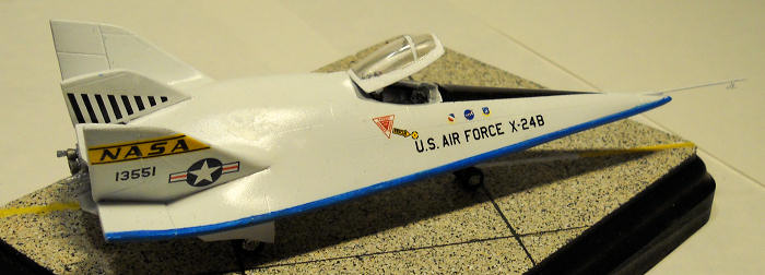
The original X-24 was a short and pudgy
aircraft with two outer fins and a center fin. After its modification the X-24B
emerged as a flying flat iron.
When the arguably ugly X-24A emerged as the X-24B it
was sleek triangular craft that would have looked right at home in a science
fiction film.
| THE KIT |
The Mach 2 X-24 is a dual kit of the
X-24A and X-24B. I will be addressing the assembly of the X-24A in a later
review but for this section the comments will be common to both reviews. When
you open the thin box you are greeted by a single grey sprue that is bagged.
Rolling around loose in the bag are four injection molded canopies. Ideally you
should only need two. At first glance I was pleasantly surprised by the quality
of the parts but once I removed the sprue from its bag and had a closer look I
could see there were some issues. There was a fair amount of flash and excess
plastic where it shouldn’t be. One of the main gear wells for
 the X-24B
was completely filled in with plastic and one of the two interior tubs was
misshapen. The plastic feels soft and a little greasy and there are many ejector
pin towers that need to be sanded, snipped or otherwise dealt with. The canopies
are thick and cloudy and also suffer from flash. One of the four canopies had a
chunk of plastic taken out of one side as if it had been roughly clipped from a
sprue. The control panels are chunky and badly marred but once cleaned up they
have ok detail for the scale. Smaller parts for the most part need clean up and
many could do with being replaced with aftermarket or scratchbuilt items.
the X-24B
was completely filled in with plastic and one of the two interior tubs was
misshapen. The plastic feels soft and a little greasy and there are many ejector
pin towers that need to be sanded, snipped or otherwise dealt with. The canopies
are thick and cloudy and also suffer from flash. One of the four canopies had a
chunk of plastic taken out of one side as if it had been roughly clipped from a
sprue. The control panels are chunky and badly marred but once cleaned up they
have ok detail for the scale. Smaller parts for the most part need clean up and
many could do with being replaced with aftermarket or scratchbuilt items.
The instructions comprise a single sheet of paper that is supposed to suffice for the assembly of both aircraft. Suffice to say they are not detailed but the X-24 is not a really complex aircraft either so if you armed with reference photos you will find them almost adequate. There is a single small sheet of decals that contains decals for both kits. They are glossy and thick and the printing appears a little blurry to my eye. Unfortunately there are only two yellow NASA Tail flashes included when there should be four, one for the outer portion of both fins for the X-24A & B. NASA meatballs are not very well printed and neither are the Air Force Material Command shields that appear on the X-24B
| CONSTRUCTION |
Getting Started:
Before actual assembly started I spent
a lot of time removing parts from the single sprue and cleaning them up and
figuring out if I could use them or if they required an alternate strategy.
I decided from the word go that I would
treat this as a resin kit. Everything requires clean up and some modeling skills
are required. Based on how soft the plastic was I decided to use super glue for
assembly.
I was afraid that a hot glue like Testors Plastic Cement would be
too aggressive on the soft plastic. The X-24B was given preference in build
order because it is my favorite of NASA’s lifting body aircraft. I cherry picked
the best parts for the X-24B as many of the A & B parts are simply duplicates.
This decision will come back to haunt me when I start on the X-24A but we will
cross that bridge later.
I started with what I considered the
most challenging aspects of this project, the port main gear well and the
interior. After picking the better of the two interior tubs I started to cut and
scrape the excess plastic from it. The tub is molded as a single piece and is
badly marred by an ejector pin crater in the center of the floor and flash
everywhere. I started at the flash with an x-acto blade and files and then tried
to deal with the crater in the floor. The crater was ugly and deep. There was
also a pile of plastic built up in one corner as well. I decided that the tub
was only partially salvageable.
So, I got out the razor saw and removed the fore and aft
bulkheads. With those removed I was able to sand the cockpit floor until it was
flat and to sand the walls until they were flush and square with the floor.
I used
the bulkheads I removed as templates to make replacements from styrene sheet and
then tacked them in place with super glue.
The X-24 used a Weber ejection seat and
the kit part bears little resemblance to the seat that was in the real aircraft.
My first plan was to just fudge it but after cleaning up the kit part to see
what I had to work with I decided that I would need to replace the seat with
something more convincing.
There are no X-24 ejection seats available from the
aftermarket folks. No surprise there.
 However
the F-101 used a Weber seat and True details offers an aftermarket F-101 seat.
It is not 100% accurate but it looks a lot better than the kit part and has a
similar look to the X-24 seat. Conveniently you get two in a pack so I will have
one for both the X24A & B.
However
the F-101 used a Weber seat and True details offers an aftermarket F-101 seat.
It is not 100% accurate but it looks a lot better than the kit part and has a
similar look to the X-24 seat. Conveniently you get two in a pack so I will have
one for both the X24A & B.
All that work left the interior in good
shape. Not intricate but at least a little busier than what you get to start
with. Next I attacked the plastic filled port main gear well. I had no illusions
of saving this part so I grabbed some styrene sheet and used the starboard well
as a master to make the port well from scratch.
This went much quicker than I expected and in no time I
had a passable facsimile of a landing gear well and when it was installed it
looked the part just great.
Moving along nicely:
After all of this was accomplished I
installed the gear wells in the lower fuselage and the interior tub in the upper
fuselage half. The rear plate/engine mount was installed at this point as well.
It fit poorly but that may be as much the fault of my aggressive anti-flash
efforts as it is the kits. I should note that the plastic in the kit is rather
soft and sanding and cutting should be done with caution.
Once the interior bits were dry I
assembled the upper and lower fuselage halves and filled the seam along the
leading edge of the fuselage. Things fit better than I expected they would and
clean up was helped by the fact that the only real seams were around the leading
and trailing edges of the lifting body.
With the fuselage together I glued on
the outer fins. These fit ok but required a bit of filling on the inboard seams
and at the point where the leading edges meet the fuselage. I then installed the
center fin. I think that this fin is off in how it sits but I can’t from the
pictures I have looked at and it was super glued in place so I will just live
with it.
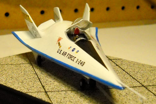
At this point I took one of the
canopies and sanded it to fit the canopy opening on the fuselage. Once it fit I
sanded it down with progressive finer micro mesh sanding sticks and then hit it
with a gloss coat and this greatly improved its clarity.
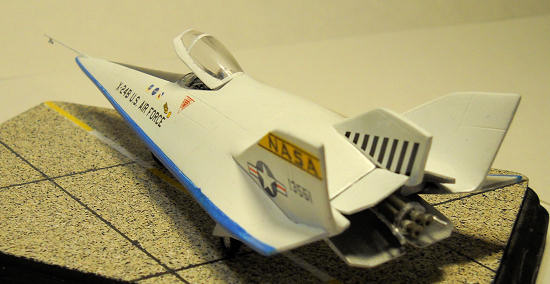
While the canopy was drying I built the XLR-11 rocket engine. It went together OK except that there is not enough room on the engine face for all four nozzles so I did the best I could. The nozzles were a real pain to clean up and I will most likely figure out a strategy for replacing them altogether when I build the X-24A. They also did not fit in the holes drilled on the mounting plate. The holes were drilled too close to each other. So, I did my best and got them on there in some kind of order. After that was together and drying, I added some detail that I had sanded off the fuselage rear plate and then added the outer flaps on the outside of the fins.
| COLORS & MARKINGS |
After doing some more filling and
sanding of various problem areas I masked the canopy and secured in over the
cockpit with silly putty and then shot the entire fuselage with Tamiya acrylic
silver. I like to use silver as a primer for tough projects as it shows all of
the flaws that I still need to fix.
After I had addressed the issues
brought forth by the primer coat I was ready to start painting for real. There
is a great photo in the NASA Dryden photo gallery of NASA research pilot Bill
Dana in front of the X-24B after its final flight in 1975.
Dana is wearing
 his
infamous pink boots with yellow daisies and cream colored g-suit while he is
interviewed by a local TV crew.
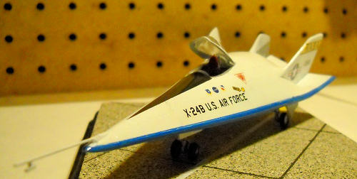
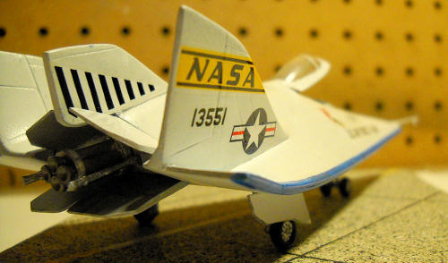
The X-24B behind him is in overall white with a black
anti-glare panel and sky blue leading edge. I decided to paint my X-24 as it
appeared for this final flight.
his
infamous pink boots with yellow daisies and cream colored g-suit while he is
interviewed by a local TV crew.
The X-24B behind him is in overall white with a black
anti-glare panel and sky blue leading edge. I decided to paint my X-24 as it
appeared for this final flight.
First I sprayed a couple of coats of
white and then masked everything but the leading edges and then sprayed them
Tamyia sky blue. Once that was dry I unmasked and discovered that blue overspray
had still made it into the white so I masked the leading edges and re-sprayed
the white areas where they needed it.
Then I masked the black Anti-glare panel and painted
that.
Once everything was dry I hit it with a coast of Testors Gloss Coat.
The kit decals were iffy so I went
ahead and purchased a set of decals from Don’s Model Works. They sell a
vacuformed model of the X-24 and they sell the decals separately. They are a
vast improvement over the kit decals and they layed down very nicely with a
little setting solution. I got two national insignia from the spaces box to
complete things and when everything was applied and set I sprayed a gloss coat
to seal everything in.
| FINAL CONSTRUCTION |
At this point I attached the engine and
fuel dumps, landing gear, gear doors and rear fuselage flaps. Everything went
together without much trouble. In truth the landing gear and fuel dumps should
be replaced with better items but at this point in the project I was feeling a
little spent and decided I could live with what was in the box after I had
cleaned the parts up a bit.
My last task was to attach the nose probe which I replaced with brass wire and at that point I declared this project done.
| CONCLUSIONS |
This was a challenging kit despite
having a fairly low parts count. However it did not present any challenges an
average to slightly better than average modeler could not handle. Sure there was
some scratch building involved but nothing too drastic just a wheel well and
some interior bits. This would really be a good kit for someone who wanted to
try stretching their skills a bit. In the end the builder will be rewarded for
their efforts with a very unique and interesting model of a subject that is not
likely to be kitted by more mainstream manufacturers.
| REFERENCES |
Martin
Marietta X-24B, Wikipedia
http://en.wikipedia.org/wiki/X-24B
Lockheed
L-301, Wikipedia
http://en.wikipedia.org/wiki/Lockheed_L-301
April 2011
If you would like your product reviewed fairly and quickly, please contact me or see other details in the Note to Contributors.