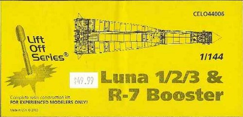
Cutting Edge 1/144 R7 ICBM
|
KIT # |
CELO44006 |
|
PRICE: |
$49.99 |
|
DECALS: |
none |
|
REVIEWER: |
|
|
NOTES: |
Resin kit |
|
HISTORY |
 The R-7 missile was designed and specifications written in 1953, serving
as the basis for the most famous family of boosters ever developed.[1] By
1954, engine development was underway at the GDL. In 1955, the testing
launch site at Baykonur was selected.[2] The booster was built at the
Kuznetsov factories at Kuybyshev.[3] In April 1956 the first R-7 rockets
were finished and ready for testing and engine testing began.[4] From
August, until Dec. 1956, launch equipment for the R-7, was installed at
Baykonur.[5] After this, an R-7 test article was used to test the ground
support equipment.[6] The first flight version R-7 was rolled out to the
launch pad after two months of checkout, on May 5, 1957. The rocket was
launched on May 15, only to fail after 50 seconds of flight. After three
more failures, the first successful flight of the R-7 occurred on August
3. The rocket test flight terminated at the Kamchatka peninsula. The
second successful flight was on Sept. 7, with Premier Nikita Khrushchev
viewing the launch.
The R-7 missile was designed and specifications written in 1953, serving
as the basis for the most famous family of boosters ever developed.[1] By
1954, engine development was underway at the GDL. In 1955, the testing
launch site at Baykonur was selected.[2] The booster was built at the
Kuznetsov factories at Kuybyshev.[3] In April 1956 the first R-7 rockets
were finished and ready for testing and engine testing began.[4] From
August, until Dec. 1956, launch equipment for the R-7, was installed at
Baykonur.[5] After this, an R-7 test article was used to test the ground
support equipment.[6] The first flight version R-7 was rolled out to the
launch pad after two months of checkout, on May 5, 1957. The rocket was
launched on May 15, only to fail after 50 seconds of flight. After three
more failures, the first successful flight of the R-7 occurred on August
3. The rocket test flight terminated at the Kamchatka peninsula. The
second successful flight was on Sept. 7, with Premier Nikita Khrushchev
viewing the launch.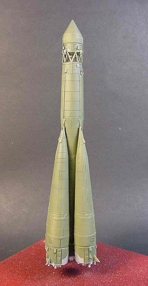 The R-7 was originally built as the Soviets first ICBM, but it was never
deployed in significant numbers. The missile was found to take too long
to fuel and launch to be an effective weapon. It also required large
above ground launch facilities that were very vulnerable to attack. It
could also only stand by fueled for 24 hours before the propellant line
seals and valves began to degrade dangerously. Test flights of the
missile continued in April 1958 then stopped until April 1959 and
continued through January, 1960 with tests at full range, some with
accuracy of 2 km. in the target region of the Pacific where 3 Soviet
ships and US intelligence forces observed the reentry. There were less
than 20 test flights, of which more than half failed. The U.S. achieved a
slightly better failure rate during testing of the first 35 Air Force
Atlas ICBM's. By Aug. 1961, there were only four R-7 ICBM's in
operational service. This included two missiles in storage to reload the
two operational launch pads at Plesetsk.
The R-7 was originally built as the Soviets first ICBM, but it was never
deployed in significant numbers. The missile was found to take too long
to fuel and launch to be an effective weapon. It also required large
above ground launch facilities that were very vulnerable to attack. It
could also only stand by fueled for 24 hours before the propellant line
seals and valves began to degrade dangerously. Test flights of the
missile continued in April 1958 then stopped until April 1959 and
continued through January, 1960 with tests at full range, some with
accuracy of 2 km. in the target region of the Pacific where 3 Soviet
ships and US intelligence forces observed the reentry. There were less
than 20 test flights, of which more than half failed. The U.S. achieved a
slightly better failure rate during testing of the first 35 Air Force
Atlas ICBM's. By Aug. 1961, there were only four R-7 ICBM's in
operational service. This included two missiles in storage to reload the
two operational launch pads at Plesetsk.
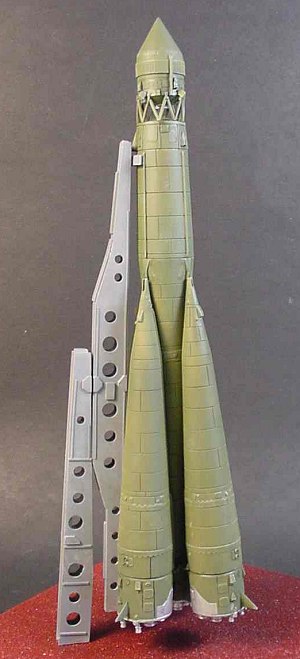
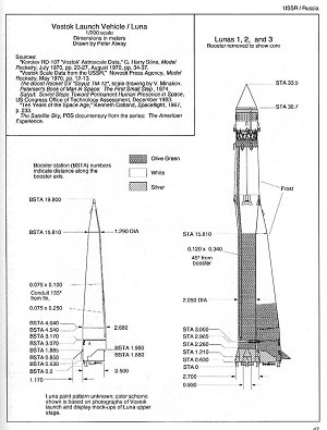
The R-7's were taken out of service by 1967 and new launch facilities with an enclosed service structure buildings were built to serve as space launch pads for the R-7 booster. The R-7 rocket consisted of five parts, a core stage 2.95 meters in diameter and 28 meters long, which was surrounded by four strap-on boosters, each 19 meters long and three meters in diameter. The booster was 10.3 meters diameter at the base, from tail fin to tail fin. The basic R-7 was used to launch early Sputniks which were light enough to achieve orbit using only the core of the booster as a final stage. After several launches, the test flights stopped in July, 1958, for a year of redesign to perfect the booster for operational use. The R-7 used an RD-107 rocket engine in each strap-on booster.
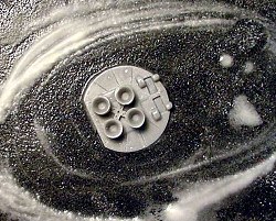
 Development of the RD-107 and RD-108 engines started in 1954 at the Gas
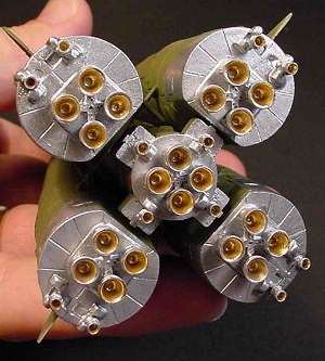
Dynamics Laboratory in Leningrad. The RD-107 had four main nozzles with
two steering vernier engines which gimballed on one axis, the main
engines did not gimbal. Each RD-107 engine consisted of four combustion
chambers, feed by a single turbo-pump mounted above the chambers. The
chambers were the same basic technology as the German V-2 engine chamber.
Each had the same thrust as a V-2 engine, but the chamber pressure was
four times higher. The core stage used a RD-108 engine, which was the
same as the RD-107, but with four steering verniers.
Development of the RD-107 and RD-108 engines started in 1954 at the Gas
Dynamics Laboratory in Leningrad. The RD-107 had four main nozzles with
two steering vernier engines which gimballed on one axis, the main
engines did not gimbal. Each RD-107 engine consisted of four combustion
chambers, feed by a single turbo-pump mounted above the chambers. The
chambers were the same basic technology as the German V-2 engine chamber.
Each had the same thrust as a V-2 engine, but the chamber pressure was
four times higher. The core stage used a RD-108 engine, which was the
same as the RD-107, but with four steering verniers.
To start the RD-107 and RD-108 type engines, propellant valves open and propellant flows through the pumps under force of gravity. The propellant is ignited by pyrotechnics and the engine burns at what is called intermediate thrust. As the pumps are turned by the propellant flow, they also drive two small pumps that feed hydrogen peroxide into a gas or steam generator. The gas generator (also called an APU or Auxiliary Power Unit) produced a large amount of steam that drives the propellant pumps. This creates an increased pump speed and feeds more propellant into the combustion chamber. The engine then runs at full thrust. The gas generator exhaust also flows through a heat exchanger to warm nitrogen that pressurizes the booster's propellant tanks. The exhaust is then expelled into the engine exhaust. The engines also use regenerative cooling, circulating the cool Kerosene fuel around the nozzle in order to cool it. Many of the RD-107 and RD-108 engine parts were made of Bronze alloys to conduct heat away from engine parts.
|
THE KIT |
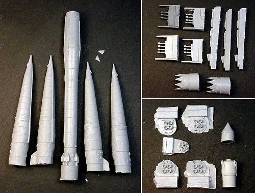
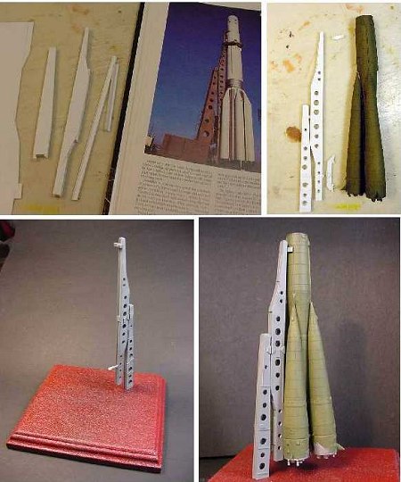
 This kit is one of the latest offerings in Cutting Edge's new "Lift Off"
series of real space subjects. As expected from Cutting Edge, the resin
castings are very nearly flawless with no mis-aligned mold seams, air
bubbles, or other typical resin casting faux pas sometimes found among
today's resin kit manufacturers. All of the parts are still attached to
their casting sprues or plugs, which will certainly make an impressive
pile of scrap after they are removed. My kit came in two bags, large
parts in one, small parts in the other. My only complaint about the kit
is the lack of packing material. I found several broken pieces from the
kit parts banging into each other, the strap-on booster fins and small
details around the 3rd stage booster.
This kit is one of the latest offerings in Cutting Edge's new "Lift Off"
series of real space subjects. As expected from Cutting Edge, the resin
castings are very nearly flawless with no mis-aligned mold seams, air
bubbles, or other typical resin casting faux pas sometimes found among
today's resin kit manufacturers. All of the parts are still attached to
their casting sprues or plugs, which will certainly make an impressive
pile of scrap after they are removed. My kit came in two bags, large
parts in one, small parts in the other. My only complaint about the kit
is the lack of packing material. I found several broken pieces from the
kit parts banging into each other, the strap-on booster fins and small
details around the 3rd stage booster.
|
CONSTRUCTION |
 The first step is the removal of all pour lugs and sprues. I cut the
large lugs off the bottoms of the boosters using a band saw, with cleanup
on the bench top belt sander. The smaller pieces were liberated using an
x-acto knife and a little sandpaper took the parting lines and flash off.
The first step is the removal of all pour lugs and sprues. I cut the
large lugs off the bottoms of the boosters using a band saw, with cleanup
on the bench top belt sander. The smaller pieces were liberated using an
x-acto knife and a little sandpaper took the parting lines and flash off.
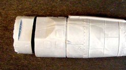
 The bottom pieces of the boosters were slightly warped so they were all
wet sanded on the mating side to make a nice flat surface. They were then
glued onto the bottoms of each of the boosters and the edges puttied and
sanded. The broken fins on the strap on boosters are also re-attached.
The small vernier rockets are cut off their sprues and attached to the
bottoms of each booster, 4 for the central core and two for each strap
on.
The bottom pieces of the boosters were slightly warped so they were all
wet sanded on the mating side to make a nice flat surface. They were then
glued onto the bottoms of each of the boosters and the edges puttied and
sanded. The broken fins on the strap on boosters are also re-attached.
The small vernier rockets are cut off their sprues and attached to the
bottoms of each booster, 4 for the central core and two for each strap
on.
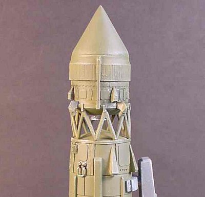
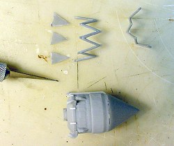 At this point, the third stage assembly is given some scrutiny. The tiny
tabs around the lower circumference of the booster were all broken
somewhere in between the factory and my house, so they are replaced with
very small strips of plastic. The nose cone and the two halves of the
truss work are liberated from their generous sprues and given a good
sanding to remove flash and seams. These parts are all glued together and
set aside to dry.
At this point, the third stage assembly is given some scrutiny. The tiny
tabs around the lower circumference of the booster were all broken
somewhere in between the factory and my house, so they are replaced with
very small strips of plastic. The nose cone and the two halves of the
truss work are liberated from their generous sprues and given a good
sanding to remove flash and seams. These parts are all glued together and
set aside to dry.
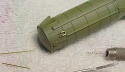 Two small vents are attached to the central core, along with a tiny brass
wire antenna bent to fit into tiny holes drilled into the side.
Two small vents are attached to the central core, along with a tiny brass
wire antenna bent to fit into tiny holes drilled into the side.
Fit Problems:
 I noticed almost immediately that the strap on boosters would need some
help staying put when attached to the central booster, and to complicate
the problem the detail that rings the central booster stands out too far,
thereby causing a noticeable gap at the top attachment point of the
boosters. I cut the raised detail off, but the problem persisted with the
top attachment. To solve the problem of the weak joints, I drilled holes
into the boosters and installed small pegs which, when assembled, would
hold all of the boosters together without compromising any of the other
glued joints.
I noticed almost immediately that the strap on boosters would need some
help staying put when attached to the central booster, and to complicate
the problem the detail that rings the central booster stands out too far,
thereby causing a noticeable gap at the top attachment point of the
boosters. I cut the raised detail off, but the problem persisted with the
top attachment. To solve the problem of the weak joints, I drilled holes
into the boosters and installed small pegs which, when assembled, would
hold all of the boosters together without compromising any of the other
glued joints.
|
CAMOUFLAGE & MARKINGS |
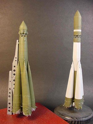
 With the strap on boosters, third stage and central core assembled, I
washed all of the parts using a grease cutting cleaner (my preference is
Formula 409 because it does not leave a residue) rinsed, and dried with a
towel. The parts were primed with Duplicolor sandable primer and polished
with a soft cloth to remove the rough surface texture. All of the parts
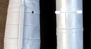
were then painted olive green acrylic, lightened 4:1 with white. The
lighter color will counter the dark wash applied later. When the base
color is dry, the lower parts of each booster are masked and sprayed with
chrome silver enamel paint and the rocket nozzle interiors are painted
with a 2:1 mix of gold and bronze enamel paint.
With the strap on boosters, third stage and central core assembled, I
washed all of the parts using a grease cutting cleaner (my preference is
Formula 409 because it does not leave a residue) rinsed, and dried with a
towel. The parts were primed with Duplicolor sandable primer and polished
with a soft cloth to remove the rough surface texture. All of the parts
were then painted olive green acrylic, lightened 4:1 with white. The
lighter color will counter the dark wash applied later. When the base
color is dry, the lower parts of each booster are masked and sprayed with
chrome silver enamel paint and the rocket nozzle interiors are painted
with a 2:1 mix of gold and bronze enamel paint.
 After all of the parts are painted, the strap on boosters and third stage
are all glued together securely.
After all of the parts are painted, the strap on boosters and third stage
are all glued together securely.
Peter Alway's book "Rockets of the World" is used as the painting
reference.
Weathering:
Very little weathering is required because these rockets had only a short
exposure to the elements. Simple light green drybrush for the highlights
and a dark wash around some of the heavier details and interior spaces
give a nice accent.
|
FINAL CONSTRUCTION |
I could not find any type of reference for the early R-7 transport or
launch structure, so I ventured off the path of being 'historically
accurate' to being 'just plain neat looking'. I found a unique looking
transport gantry in one of my reference books, which actually pictured
the Proton-Mir stack. Being the only clear photograph of a Russian
transport and support structure, I decided to use it.
Construction is simple and straightforward. The two parts of the stand
are basic box assemblies using .030 plastic and 3/16" "H" beams.
Lightening holes are drilled into the boxes using my drill press and
small forstener bits, and then small strips of plastic are added for
surface detail. Both assemblies are connected with brass wire and
attached to the display base with steel wire which runs up through the
stand and down into holes drilled into the base. Another small brass rod
securely connects the rocket to the stand.
|
CONCLUSIONS |
 Although the fit problems with the strap on boosters presented a
technical (if not accuracy) problem, the entire kit went together very
well. This is an easy enough model for any novice resin kit builder to
successfully tackle. I am very happy with the level of detail on this
model, especially when compared to the Start kits which for so long were
the only kits of Russian rockets available.
Although the fit problems with the strap on boosters presented a
technical (if not accuracy) problem, the entire kit went together very
well. This is an easy enough model for any novice resin kit builder to
successfully tackle. I am very happy with the level of detail on this
model, especially when compared to the Start kits which for so long were
the only kits of Russian rockets available.
|
REFERENCES |
Various internet sites
Rockets of the World - Third Edition
http://members.aol.com/Satrnpress/products.htm
October 2003
Copyright ModelingMadness.com If you would like your product reviewed fairly and quickly, please contact
the editor or see other details in the Note to
Contributors.