Sword 1/72 FJ-3 Fury
| KIT #: | 72108 |
| PRICE: | 1600 yen when new (2000) |
| DECALS: | Three options |
| REVIEWER: | Joel Hamm |
| NOTES: |
|
| HISTORY |
Judging by the chatter on modeling sites, everyone and his cat has one of these kits in the stash, as well as a profound knowledge of the subject aircraft’s development. I’ll simply fulfill the required “History” paragraph by stating that the FJ-2/3 represented the midpoint of the F-86 Sabre Jet’s navalization; bookended on the low side by the straight wing FJ-1, and on the upper limit by the Schwartzenagered FJ-4. By all accounts no variant saw combat action, but I’ve learned not to believe everything printed in books or on The Magic Screen.
| THE KIT |
 Sword
released the Fury bout a year ago to universal acclaim by modelers who had
theretofore navalized their own sabres by slathering them in blue paint and
pretending not to notice discrepancies in landing gear, canopy, inlet, and other
external differences. Though billed as short run, the box contents are perfectly
up to Japanese state of the art snuff. Transparencies are injected: clear,
optically OK, but over-scale thickness; which of course must be tolerated absent
a willingness to diddle with vacu-forms. For undiscernible reasons, the ejection
seat is cast as two resin pieces. The headrest part should be considerably
fore-aft filed; if not for aesthetics or realism, to prevent it from mashing
against the canopy and breaking off the finely-molded activation handle. For the
sake of earning a true “multi-media” rating, the kit could / should have
included, but did not, an etched fret of seat belts, torque links, wing fences
and drop tank fins.
Sword
released the Fury bout a year ago to universal acclaim by modelers who had
theretofore navalized their own sabres by slathering them in blue paint and
pretending not to notice discrepancies in landing gear, canopy, inlet, and other
external differences. Though billed as short run, the box contents are perfectly
up to Japanese state of the art snuff. Transparencies are injected: clear,
optically OK, but over-scale thickness; which of course must be tolerated absent
a willingness to diddle with vacu-forms. For undiscernible reasons, the ejection
seat is cast as two resin pieces. The headrest part should be considerably
fore-aft filed; if not for aesthetics or realism, to prevent it from mashing
against the canopy and breaking off the finely-molded activation handle. For the
sake of earning a true “multi-media” rating, the kit could / should have
included, but did not, an etched fret of seat belts, torque links, wing fences
and drop tank fins.
The injected sprues hold
several alternate parts to allow building either early or late Dash Three’s.
They also hold parts which are at best unnecessary, and at worst troublesome. No
need exists for boxing in the wheel wells with bulkhead parts 16, 29, 55, and
56. If the sliding canopy deck (23) and rear wall (48) are attached to the
 clear part,
harbor no expectation of affixing the assembly in either the open or closed
position; nor of gluing on the windshield if a heads-up display is represented
by sticking clear part 60 to the rectangular nubbin on instrument cowl 36. As a
matter of fact, said nubbin should be filed off completely and aforementioned
cowl narrowed by beveling front and side edges. The floor (15) to the tailskid
well can be chucked into the spare parts bin; along with unidentifiable landing
gear pieces 45 and 45, which can’t be seen in photos.
clear part,
harbor no expectation of affixing the assembly in either the open or closed
position; nor of gluing on the windshield if a heads-up display is represented
by sticking clear part 60 to the rectangular nubbin on instrument cowl 36. As a
matter of fact, said nubbin should be filed off completely and aforementioned
cowl narrowed by beveling front and side edges. The floor (15) to the tailskid
well can be chucked into the spare parts bin; along with unidentifiable landing
gear pieces 45 and 45, which can’t be seen in photos.
Clear parts are provided for navigation lights, but using them requires filing notches in the wingtips. They are more neatly represented by dabs of green and red paint, even though in 1:1 real life scale they would be near invisible. If under wing stores and fueling probes are to be used, locating holes must be drilled; a procedure preferable to forcing clean-airframe builders to putty and sand pre-punched holes.
| CONSTRUCTION |
 Other parts
and assemblies are troublesome only because the instructions are fuzzy on their
proper placement. The cockpit / intake sub-assembly should be glued just forward
of the rib molded into the starboard fuselage half, not against it, as the
instructions indicate. The jet pipe goes behind its rib.
Other parts
and assemblies are troublesome only because the instructions are fuzzy on their
proper placement. The cockpit / intake sub-assembly should be glued just forward
of the rib molded into the starboard fuselage half, not against it, as the
instructions indicate. The jet pipe goes behind its rib.
Step 12 shows intake scoops 67 glued into rectangular recesses in the rear fuselage flanks. NEGATIVE, NEGATIVE! The scoops go behind the recesses, which represent air inlet ramps.
Some builders had complained of unmanageable intake lip gaps and a fatal fatness of wing camber vs. mating root. Neither was noted in this kit. Nothing more than the usual filling and fairing was required at the under fuselage seam and wing to body join.
| COLORS & MARKINGS |
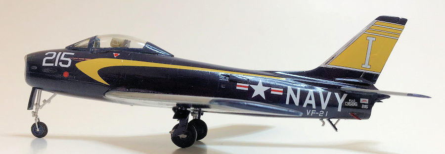
The sole object of getting
Fury-ous is to dress the sexy Sabre in sexier gloss blue; so why did Sword
include only decals for 3 boring grey over white liveries? At the time of
purchase Print Scale #72-083 was the only aftermarket alternative. Several
vendors have since issued preferable sheets. I may be wrong, as I often am, but
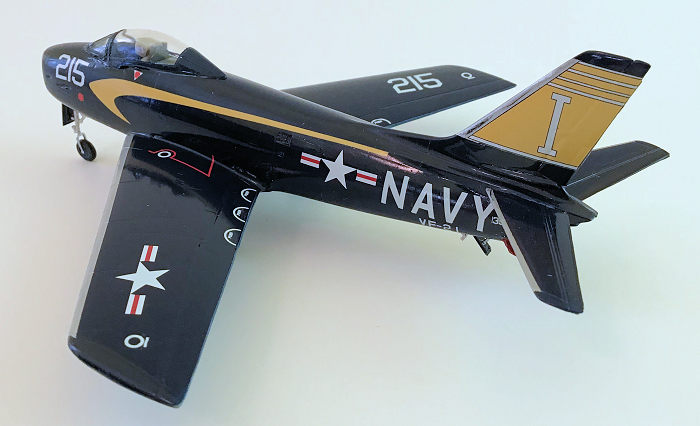
PS’s yellow appears overly washed out. Vertical fin markings are too narrow,
leaving a blue trailing edge stripe on the rud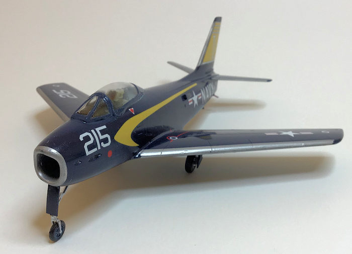 der,
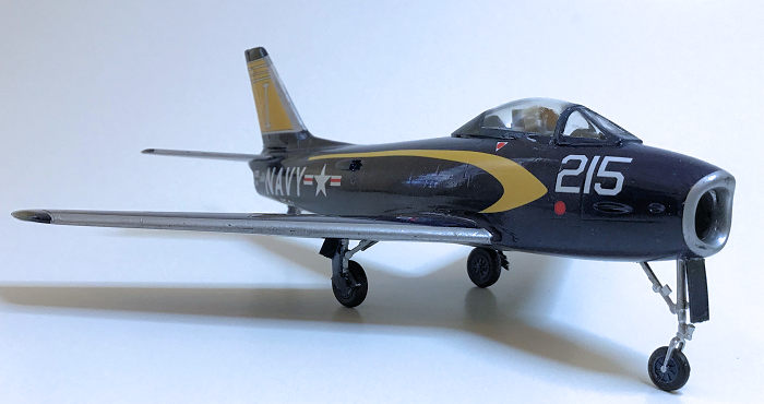
unless the leading edge silver is extended improperly aft. The white NAVY
letters seem slightly oversize, judging by the need to truncate numerals from
the aircraft type and serial numbers in order to fit them and exhaust warning
placards on the remaining length of fuselage.
der,
unless the leading edge silver is extended improperly aft. The white NAVY
letters seem slightly oversize, judging by the need to truncate numerals from
the aircraft type and serial numbers in order to fit them and exhaust warning
placards on the remaining length of fuselage.
The decals apply easily enough, but rather than relaxing and snuggling into depressions on application of setting fluids (I tried them all) they tighten to drum skins, an especially egregious booger across the rudder hinge line.
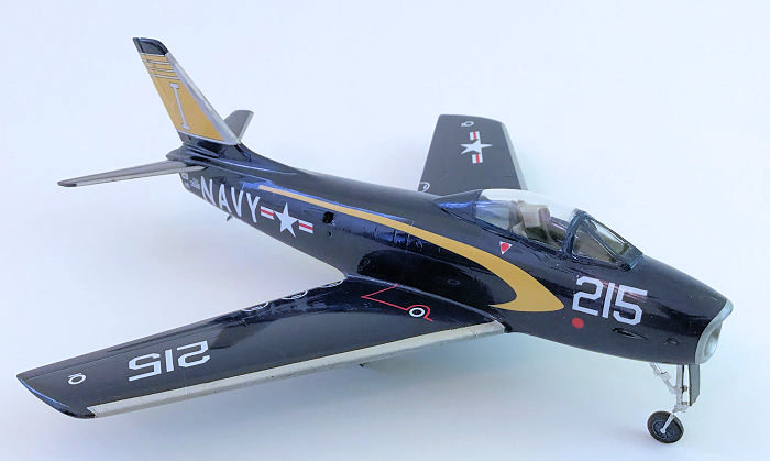
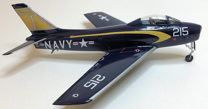
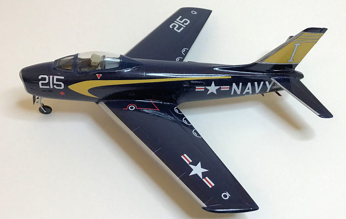
Print Scale’s most serious failing is a lack of adequate reference drawings. Only one side view is shown for each of 6 planes. An accompanying b&w photo for the FJ4’s is uselessly fuzzy. A single plan view is provided for technical stencils; leaving the builder to assume that all six examples shared identical markings, and to decide whether the national insignia should be placed perpendicular to the longitudinal axis, as shown on the top view, or aligned with the chord line, as from below. In response to a Readers Forum query, posters with access to reference materials (I gave my Monogram Guides away when I downsized) said that in this early 1955 scheme airplane numbers were not painted on the wings; but no other location was suggested for the included “215’s”, so on the outboard upper and lower panels they went. Ditto the “PUSH” semi-circles and other tidbits.
 National
insignia came from the kit decals and behaved more accommodatingly than Print
Scale’s.
National
insignia came from the kit decals and behaved more accommodatingly than Print
Scale’s.
Bare metal leading edges were done with chrome silver Testors automotive lacquer, which dries as hard, shiny, and instantly as Alclad.
Humbrol tinlet 15, the only available source of gloss sea blue, had its perceived over-purple-ness fixed with a zotz of Testors dark blue. That still meant losing half the contents around the lid rim, then baking the project for a full week in the backyard Arizona sun to dry all traces of tackiness.
The whole was preserved neath a coat of Johnsons / Klear / Future thinned 1/3 with 90% isopropanol; after scrubbing off a disastrous coat of Holloways Quick Shine, which had previously produced flawless test sprays. While the former dried I recovered from the latter by baking myself in the backyard Arizona sun with some 40% single malt ethanol.
| FINAL PIECES |
 Nose and
main landing gear are complicated and poorly diagramed. The instructions hint,
and photos confirm, that the nose torque scissors protrudes to the right, not
rear. Part 43 looks little like a torque link so, along with oversized part 57,
it was deleted pending Hannants’s delivery of a photo etched fret of landing
gear details.
Nose and
main landing gear are complicated and poorly diagramed. The instructions hint,
and photos confirm, that the nose torque scissors protrudes to the right, not
rear. Part 43 looks little like a torque link so, along with oversized part 57,
it was deleted pending Hannants’s delivery of a photo etched fret of landing
gear details.
If the canopy deck and bulkhead are omitted the sliding section will sit passably well in place. The fit to it and the forward fuselage of the windscreen is lamentable. If choosing a closed display the 2 halves should first be mated together, then the joining surfaces to and on the fuselage sculpted; otherwise extensive fairing and caulking with epoxy or PVA glue will need to hide the gaps and overhangs.
Inaccuracies surely exist between this model and the airplane it depicts. The lack of wing slats was easily cured with a few strokes of a scriber. The under-cambered leading edge could have been puttied over, but nobody gets to look down there. Other geometric complaints are filed under “It’s Just a Plastic Toy”.
| CONCLUSIONS |
Can’t understand why some modelers have consigned such a fine, if challenging, kit to the Stash of Doom.
15 February 2019
Copyright ModelingMadness.com
If you would like your product reviewed fairly and fairly quickly, please contact the editor or see other details in the Note to Contributors.
Back to the Main Page Back to the Review Index Page Back to the Previews Index Page