Trumpeter 1/48 F-106A Delta Dart
| KIT #: | 02891 |
| PRICE: | $74.95 MSRP |
| DECALS: | Two options |
| REVIEWER: | Robert Hart |
| NOTES: | The best 1/48 F-106 kit on the market, but the weapons bay assembly suffers from poor engineering. |
| HISTORY |
 The Convair
F-106A entered service in May, 1959 and was the primary all weather interceptor
of the USAF through to the 1980s. Armed with four AIM-4 Falcon missles and one
AIM-2A Genie missile with a nuclear warhead, it would be the last dedicated
interceptor in USAF service. The F-106 was gradually withdrawn from the
interceptor role during the 1980s but drone conversions remained in service
until almost the end of the twentieth century. It never saw combat and was not
exported. The F-106 had excellent performance, was reportedly a good
“dogfighter”, and was popular with its pilots. In fact, it enjoyed a relatively
controversy free career and arguably the best known incident involving an F-106
was when one landed itself in a Montana cornfield after it's pilot ejected. The
F-106 involved in that incident is currently displayed in the National Museum of
the United States Air Force- a fitting tribute to a long serving defender of the
free world that gave the American tax payer excellent “bang for the buck”.
The Convair
F-106A entered service in May, 1959 and was the primary all weather interceptor
of the USAF through to the 1980s. Armed with four AIM-4 Falcon missles and one
AIM-2A Genie missile with a nuclear warhead, it would be the last dedicated
interceptor in USAF service. The F-106 was gradually withdrawn from the
interceptor role during the 1980s but drone conversions remained in service
until almost the end of the twentieth century. It never saw combat and was not
exported. The F-106 had excellent performance, was reportedly a good
“dogfighter”, and was popular with its pilots. In fact, it enjoyed a relatively
controversy free career and arguably the best known incident involving an F-106
was when one landed itself in a Montana cornfield after it's pilot ejected. The
F-106 involved in that incident is currently displayed in the National Museum of
the United States Air Force- a fitting tribute to a long serving defender of the
free world that gave the American tax payer excellent “bang for the buck”.
| THE KIT |
The kit represents a late model F-106A and has 209
parts (195 plastic and 14 photo-etched brass). The photo etched parts provide
seat belts, shoulder restraint harnesses, rear view mirrors, two tiny 'whatsits'
that go between the splitter plates and the fuselage, and an angle of attack
vane. Some of the plastic parts are duplicated due to sharing some sprue trees
with Trumpeter's F-106B kit, as in the case of the ejection seat and throttle
quadrant, but inexplicably, extra missiles, missile launch rails, and aft
launcher drag arms are also included. The clear parts include the windshield,
canopy (only the later blown type is provided), landing lights, lenses for the
infrared AIM-4 missile seeker heads, and covers for the upper and lower rotating
beacons. The kit's surface detail is primarily recessed panel lines, but
recessed rivets and raised panel lines are also present. The fuselage is split
vertically as is the separate fin. The rudder is separate from the fin
 and can
only be mounted in the neutral position, The wing is molded in left and right
uppers and a single piece lower. The weapons and landing gear bays are nicely
detailed and appear to be of “scale” depth. The landing gear legs, retraction
arms, and doors also show good detail, but the wheels look kind of plain and
generic. A bay between the landing gear and weapons bays housing the ram air
turbine, the lower rotating beacon, and an emergency electrical generator can be
built open or closed. Two infrared homing AIM-4, two AIM-4 radar guided, and one
AIM-2A Genie missiles are included. The weapons bay can be assembled either open
or closed . If built open, the only way the weapons load can be displayed is
with the missile launchers extended. The cockpit has a five piece ejection seat,
a tub incorporating side consoles and rudder pedals, an instrument panel, a two
piece control yoke, a throttle quadrant, an equipment tray behind the seat, and
the canopy opening /closing jack . The cockpit sidewall detail is molded on the
insides of the fuselage halves. The instrument panel and side consoles feature
raised detail, but decals are also included. I rate the cockpit detail as kind
of basic for a 1/48 kit as recently tooled (2015) as this one. The elevons and
flaps are separate and can only be mounted in the “down” position unless
modified. The air brakes can be posed closed or open and feature nice detail on
their inner faces. The engine/tailpipe/afterburner can assembly has an outer
shell into which a separate tube is inserted. Both outer shell, inner tube, and
afterburner can are split vertically into left and right hand sides. Separate
parts for the afterburner nozzle, aft end of the turbine, and a blanking
plate(?) are also included. The intakes are blanked off at their aft ends. A
pair of 360 gallon external fuel tanks are included along with their pylons The
refueling receptacle is a separate piece. Waterslide decals are included for
Florida and New Jersey Air National Guard aircraft. The decals also provide
national markings, USAF logos, serial numbers, and some stencilling for the
airframe and the missiles.
and can
only be mounted in the neutral position, The wing is molded in left and right
uppers and a single piece lower. The weapons and landing gear bays are nicely
detailed and appear to be of “scale” depth. The landing gear legs, retraction
arms, and doors also show good detail, but the wheels look kind of plain and
generic. A bay between the landing gear and weapons bays housing the ram air
turbine, the lower rotating beacon, and an emergency electrical generator can be
built open or closed. Two infrared homing AIM-4, two AIM-4 radar guided, and one
AIM-2A Genie missiles are included. The weapons bay can be assembled either open
or closed . If built open, the only way the weapons load can be displayed is
with the missile launchers extended. The cockpit has a five piece ejection seat,
a tub incorporating side consoles and rudder pedals, an instrument panel, a two
piece control yoke, a throttle quadrant, an equipment tray behind the seat, and
the canopy opening /closing jack . The cockpit sidewall detail is molded on the
insides of the fuselage halves. The instrument panel and side consoles feature
raised detail, but decals are also included. I rate the cockpit detail as kind
of basic for a 1/48 kit as recently tooled (2015) as this one. The elevons and
flaps are separate and can only be mounted in the “down” position unless
modified. The air brakes can be posed closed or open and feature nice detail on
their inner faces. The engine/tailpipe/afterburner can assembly has an outer
shell into which a separate tube is inserted. Both outer shell, inner tube, and
afterburner can are split vertically into left and right hand sides. Separate
parts for the afterburner nozzle, aft end of the turbine, and a blanking
plate(?) are also included. The intakes are blanked off at their aft ends. A
pair of 360 gallon external fuel tanks are included along with their pylons The
refueling receptacle is a separate piece. Waterslide decals are included for
Florida and New Jersey Air National Guard aircraft. The decals also provide
national markings, USAF logos, serial numbers, and some stencilling for the
airframe and the missiles.
| CONSTRUCTION |
I began building the model by re-scribing all of the kit's recessed panel lines with an Exacto scriber. I like to apply a pin wash in the panel lines of my models and I know from experience that Trumpeter's panel lines are not of consistent depth or width. By re-scribing them I ensure that the finished model's pin washed panel lines won't look like morse code messages and will have a more consistent appearance with areas that need to re-scribed after seam eradication.
I replaced the kit's cockpit parts with an Aires
aftermarket set. The Aires set has a superior level of detail, but was not a
drop fit. I used a Dremel to grind off the kit's cockpit sidewall detail on the
insides of the fuselage halves and continued grinding until the walls of the
fuselage in the cockpit area were about half as thick as they were originally
molded. I also had to file down the bottom of the Aires cockpit tub and the roof
of the kit's nose wheel well before the fuselage halves would close around the
replacement cockpit parts. The kit's molded on coaming and radar scope under the
windshield were replaced by an Aires part that also incorporates the back of the
instrument panel. The rest of the instrument panel is made up of an acetate
sheet with the instrument faces printed on it and a photo-etched panel that has
raised detail on it's face. I painted the back of the acetate sheet white and
sandwiched it between the back of the instrument panel and the photo etched
piece. I painted the cockpit with a Tamiya Acrylic mix for dark gull gray ( 1 x
XF83, 1 x XF66, 1 xXF54, and 3xXF2). I masked and sprayed selected panels on the
console tops and sidewalls along with the instrument panel and control yoke hand
grips with Tamiya Nato Black acrylic. After the black paint dried, I applied a
thin wash of paynes grey oil paint over the entire cock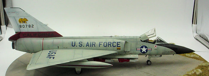 pit
before dry brushing the raised details with Testors gray enamel and highlighting
some of the switches, knobs, and buttons with red, yellow, and light gray
colored pencils. I painted the ejection seat cushion and back rest with Tamiya
olive drab acrylic, the headrest with Tamiya red acrylic, and the firing handles
with Tamiya yellow acrylic. I completed the ejection seat by adding a set of
pre-colored Eduard seat belts and shoulder harnesses and an oxygen hose
fabricated from a piece of upholstery thread, After the detail painting was
complete, I attached the photo etched rudder pedal assembly to the back of the
base of the instrument panel and glued the control yoke in it's position on the
cockpit floor.
pit
before dry brushing the raised details with Testors gray enamel and highlighting
some of the switches, knobs, and buttons with red, yellow, and light gray
colored pencils. I painted the ejection seat cushion and back rest with Tamiya
olive drab acrylic, the headrest with Tamiya red acrylic, and the firing handles
with Tamiya yellow acrylic. I completed the ejection seat by adding a set of
pre-colored Eduard seat belts and shoulder harnesses and an oxygen hose
fabricated from a piece of upholstery thread, After the detail painting was
complete, I attached the photo etched rudder pedal assembly to the back of the
base of the instrument panel and glued the control yoke in it's position on the
cockpit floor.
With the cockpit more or less completed, I began working on the other sub assemblies that had to be nstalled before the fuselage could be closed. I started with the nose landing gear bay. This bay has a roof, sidewalls, and front, back, and center bulkheads. The nose landing gear leg has to be installed before the bay can be assembled as the upper cross member fits into holes in the sidewalls. The gear leg is in separate upper and lower parts that butt join. I had no confidence that the join would be sufficient to support the weight of the model so I drilled about 1/4” into each part of the leg and inserted a 1/16” diameter steel pin. I painted the gear leg and retraction jack with Tamiya white surface primer followed by a paynes gray oil pain wash and wrapped a strip of Bare Metal Foil around the oleo section of the leg. While I was at it I gave the main gear legs the same treatment. I painted the interior sides of the nose gear bay parts with a Tamiya Acrylic mix for interior green ( 2xXF3 + 1xXF5) followed by a burnt umber oil paint wash and then dry brushed with a slightly lightened version of the interior green mix. I used a silver colored pencil to highlight the molded on wires, hoses, and miscellaneous details in the bay. I then assembled the bay while trapping the gear leg between the sidewalls. Surprisingly, for what was basically just a rectangle open on one side, the gear bay parts did not fit well with each other and I ended clamping the parts while I flooded the joints with thin super glue.
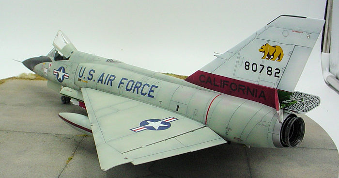
I replaced the kit's engine parts with a Wolfpack engine nozzle set. The Wolfpack set offers a higher level of detail, has fewer parts, and the jet pipe and afterburner can are seamless. The jet pipe has pins that plug into the same sockets on the insides of the fuselage halves intended for the kit parts. I was concerned that the resin pins wouldn't be strong enough to hold the somewhat heavy parts so I replaced them with steel pins. I painted the jet pipe, afterburner can, and afterburner nozzle with Alclad steel and then dry brushed them with Testors flat silver enamel.
The kit's weapons bay has a single part for the roof and sides with separate pieces for the bulkheads at each end. I painted all of the weapons bay parts with the Tamiya Acrylic interior green mix followed by a burnt umber oil paint wash and dry brushing with a lightened shade of the interior green. I again used a silver colored pencil to highlight the molded on wiring, hoses, and bolt heads. After the paints and the wash dried I attached the bulkheads to the roof/sides part and set the sub-assembly aside while the glue cured.
I installed the nose landing gear bay, weapons bay, cockpit, and engine in the right fuselage half and dry fitted it to the left fuselage half. Only the coaming/radar scope/instrument panel piece under the windshield needed to be slightly trimmed before the fuselage halves would close with only a slight step just in front of the windshield marring an otherwise perfect fit. I used thin superglue to attach the fuselage halves to each other. I glued about two inches in length at a time before sanding the seam smooth .I've found that letting super glue fully cure makes it hard to sand. After all the seams had been cleaned up, I re-scribed the panel lines that crossed the seams with an Exacto scriber and a JLC saw. I then attached the refueling receptacle, nose cone, splitter plates, and intakes. The nose cone and aft end of the intakes were not good fits and I had to fill gaps with the super glue and baby powder mix. After I sanded the joins flush, I re-scribed the panel lines.
 With the
fuselage assembly largely complete, I glued the two halves of the fin together
with thin superglue. After sanding the seams smooth, I replaced the forward ends
of the two probes on the leading edge with steel pins. Dry fitting the fin to
the fuselage revealed a sizeable gap along the mating edges and a large step
where the forward edge of the fin met the fuselage spine. I filed the mating
surfaces in an effort to minimize the gap, but still could not get the fit to
where the seam would pass as a panel line. I ended up filling the join with
Apoxie Sculpt that I smoothed with a damp Q tip to reduce the amount of sanding
needed to eliminate the seam. The Apoxie Sculpt as filler worked well enough
that only the step at the forward fin/rear fuselage spine needed to be sanded.
With the
fuselage assembly largely complete, I glued the two halves of the fin together
with thin superglue. After sanding the seams smooth, I replaced the forward ends
of the two probes on the leading edge with steel pins. Dry fitting the fin to
the fuselage revealed a sizeable gap along the mating edges and a large step
where the forward edge of the fin met the fuselage spine. I filed the mating
surfaces in an effort to minimize the gap, but still could not get the fit to
where the seam would pass as a panel line. I ended up filling the join with
Apoxie Sculpt that I smoothed with a damp Q tip to reduce the amount of sanding
needed to eliminate the seam. The Apoxie Sculpt as filler worked well enough
that only the step at the forward fin/rear fuselage spine needed to be sanded.
The main landing gear bay is completed by attaching two bulkheads and a three legged brace . If you plan on using the drop tanks, holes have to be drilled in the lower wing to accommodate the pins on the tops of the drop tank pylons. Pilot holes are molded into the inside of the lower wings, but they have a slightly smaller diameter than the pylon pins. Use the diameter of the pins to determine your drill bit size or you'll end as I did, having to enlarge holes on an assembled and painted model. The main landing gear bay is attached to the inside of the lower wing and then the entire sub-assembly is glued to the fuselage. The rear lower wing to fuselage join had a slight step that I filled with the superglue and baby powder mix before sanding flush. The left and right upper wings attached to the fuselage without needing filler. The upper wings incorporate the leading edges and the forward joins with the lower wing are along a panel lines. However, the joins were not fine enough to pass as panel lines so I filled them with the superglue and baby powder mix, sanded flush, and re-scribed the lines.
With the major airframe construction complete, I glued the windshield to the fuselage and filled the seam with Apoxie Sculpt smoothed with a moistened Tamiya triangular tipped cotton swab. I used a New Ware Advanced Masks masking set to mask the windshield. The New Ware set also includes masks for the interior and exterior of the canopy, canopy seal, natural metal areas on the intakes and tail cone, nose cone, anti glare panel, refueling receptacle, and wheels. The masks fit precisely, didn't leak, and the adhesive left no residue when they were removed. I masked off the interior of the intakes, landing gear bays, weapons bay, and cockpit with combinations of masking tape, Blu Tack, and facial tissue. With all the masking complete, it was time for paint and decals.
| COLORS & MARKINGS |
I gave the exterior surfaces of the model a coat
of Tamiya White Surface Primer. After checking the primer coat for and
correcting any areas that needed any additional filling and sanding, I
pre-shaded the panel lines and wing roots with very thin (70% thinner/30%paint)Tamiya
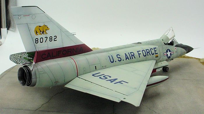
black acrylic paint. The aircraft my model was to represent had a white fin and
rudder with a broad red band at the base of the fin that also encompassed the
exterior of the air brakes. I used the primer coat for the white and masked off
the fin before applying the red band. I mixed Tamiya acrylics to match the red
in the national insignia decals for the red band. Unfortunately, I think I
missed the mark a bit because the red band ended up looking a little darker than
the red in the decals. After masking off the red band I sprayed the rest of the
exterior surfaces of the airframe along with the exterior canopy frames, and the
exteriors of the land gear doors and the weapons bay doors with a Tamiya Acrylic
mix for ADC Gray FS 16473 (1 x XF22, 1x XF23, and 5 x XF2). I applied the ADC
Gray in multiple light coats to slowly build up the coverage in order to obtain
a “shadow” effect from the pre-sha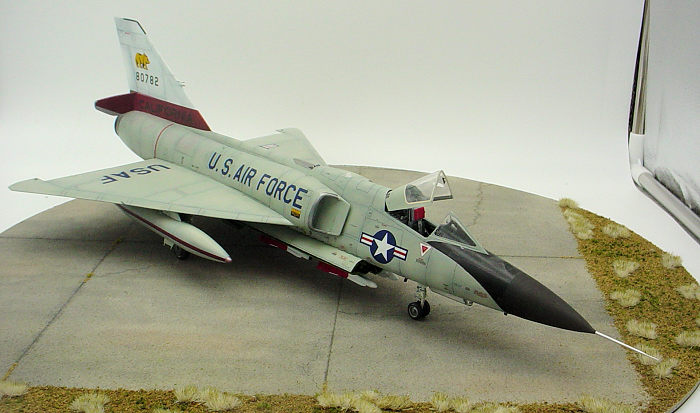 ding.
Once I was satisfied with the coverage of the ADC Gray and the paint had dried,
I masked off the anti-glare panel and sprayed it with Tamiya Nato Black acrylic.
I also masked the exteriors of the main and nose landing gear bay doors, the
auxiliary bay doors, and the weapons bay doors before spraying the interiors of
all but the nose gear bay door with the Tamiya interior green mix. I sprayed the
interior of the nose gear bay door with Tamiya white acrylic and used a .005 mm
black ink Sakura pen to simulate the prominent seal around the circumference of
the inner door. I held off on painting the nose cone as I was planning to use a
metal aftermarket pitot tube and I didn't want to risk breaking it off during
the rest of the construction process. Finally, I applied a coat of Tamiya clear
gloss acrylic to every surface that would have a decal applied to it.
ding.
Once I was satisfied with the coverage of the ADC Gray and the paint had dried,
I masked off the anti-glare panel and sprayed it with Tamiya Nato Black acrylic.
I also masked the exteriors of the main and nose landing gear bay doors, the
auxiliary bay doors, and the weapons bay doors before spraying the interiors of
all but the nose gear bay door with the Tamiya interior green mix. I sprayed the
interior of the nose gear bay door with Tamiya white acrylic and used a .005 mm
black ink Sakura pen to simulate the prominent seal around the circumference of
the inner door. I held off on painting the nose cone as I was planning to use a
metal aftermarket pitot tube and I didn't want to risk breaking it off during
the rest of the construction process. Finally, I applied a coat of Tamiya clear
gloss acrylic to every surface that would have a decal applied to it.
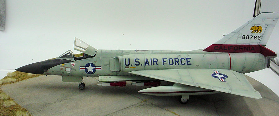
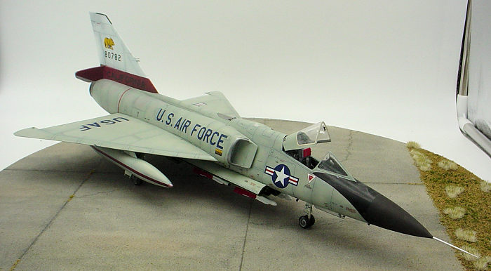
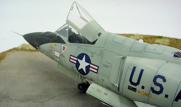
I used the markings of the 194th FIS California ANG in 1980 on the model. These markings are included on Caracal Models 48061, ANG F-106A/B Delta Dart Part 2. I also used fundekals, FD 48010, F-106A/B Stencils, As it turned out, I only used the “California” script, the bear graphic, and the serial numbers from the Caracal sheet with all of the other decals coming from the fundekals sheet except a few stencils on the missiles that came with the kit decals. The fundekals stencils are comprehensive, crisply printed, and legible. In addition to stencils, the fundekals sheet also includes dielectric panels for the antennas, and national insignias, and USAF logos. The Caracal sheet included the stripes for the drop tanks, but I opted to mask and paint those as the results that I have obtained from applying waterslide decals on compound curves has been inconsistent. It took six 2 hour sessions to apply all the decals. I was surprised to find that neither the fundekal or Caracal decals would lay down into the panel lines. Even after slicing the decals that lay across panel lines with a scalpel and dousing them with setting solution, some of them silvered. With the decal application process finished, I applied a Paynes Grey oil paint pin wash in the panel lines on the ADC gray painted areas and a tan oil paint pin wash in the panel lines of the anti-glare panel. I gave the oil paint washes a few days to dry before spraying all of the areas that would be visible on the finished model except the clear parts with a coat of Tamiya semi gloss clear acrylic.
| FINAL CONSTRUCTION |
 I began
the final assembly with the weapons bay. The bay has four doors (two on each
side), Each pair of doors attach to each other and to the lower side edges of
the weapons bay. The doors are also supported by six retraction jacks. The upper
ends of the jacks butt join to the walls of the bay and the lower ends butt join
to the inner sides of the doors. All of the attachment points are very small and
it took multiple attempts before I got all of the parts aligned and joined. I
thought getting the bay doors attached was difficult, but it was a walk in the
park compared to the challenges the missile launchers would pose. Each of the
two aft missile launchers is comprised of two pairs of drag arms, a launch
actuator, and a launch rail. The drag arms have sockets on their lower ends that
go over pins on each side of the launchers. The upper ends of the drag arms have
short pins on each side that sit in narrow troughs molded onto the roof of the
weapons bay. The upper ends of the launch actuators attach to the rear wall of
the weapons bay and the lower ends butt join to the tops of the launch rails.
The drag arms launch actuators, and launch rails all have to be attached to each
other at different angles and none of the contact points have positive locators.
I sat down to try to complete this sub-assembly for at least five consecutive
days before I managed to finish it. The forward missile launcher assembly was
slightly easier due to their being fewer parts. The launch rails are attached to
a three part crossbridge assembly that is supported by only two drag arms and
one actuator. Once the missile launchers were finished, I attached the missiles.
I was relieved when they went on with no drama.
I began
the final assembly with the weapons bay. The bay has four doors (two on each
side), Each pair of doors attach to each other and to the lower side edges of
the weapons bay. The doors are also supported by six retraction jacks. The upper
ends of the jacks butt join to the walls of the bay and the lower ends butt join
to the inner sides of the doors. All of the attachment points are very small and
it took multiple attempts before I got all of the parts aligned and joined. I
thought getting the bay doors attached was difficult, but it was a walk in the
park compared to the challenges the missile launchers would pose. Each of the
two aft missile launchers is comprised of two pairs of drag arms, a launch
actuator, and a launch rail. The drag arms have sockets on their lower ends that
go over pins on each side of the launchers. The upper ends of the drag arms have
short pins on each side that sit in narrow troughs molded onto the roof of the
weapons bay. The upper ends of the launch actuators attach to the rear wall of
the weapons bay and the lower ends butt join to the tops of the launch rails.
The drag arms launch actuators, and launch rails all have to be attached to each
other at different angles and none of the contact points have positive locators.
I sat down to try to complete this sub-assembly for at least five consecutive
days before I managed to finish it. The forward missile launcher assembly was
slightly easier due to their being fewer parts. The launch rails are attached to
a three part crossbridge assembly that is supported by only two drag arms and
one actuator. Once the missile launchers were finished, I attached the missiles.
I was relieved when they went on with no drama.
I completed the auxiliary bay between the weapons bay and the main landing gear bay with the doors open and the ram air turbine extended. The lower rotating beacon and the emergency electrical generator are attached to the right side door. The ram air turbine is attached to left side of the bay's rear wall. I painted the ram air turbine with the dark gull gray Tamiya acrylic mix, but some photos show the blades were unpainted metal.
The upper ends of the main landing gear legs have two pins that fits into sockets on the roof of the landing gear bay. Two actuators attach to each main landing gear leg and each other by pins and sockets. Pins on the ends of the upper cross bars of the actuators then slot into narrow “U” shaped channels on the roof of the bay. The torque links are in two pieces with the upper link molded integrally with the actuator for the outer landing gear bay door. The torque links attach to the gear legs by shallow tongues and grooves. The torque links need to be carefully aligned as the integral actuator's accurate positioning is required to insure that the outer gear doors hang at the correct angle to the ground. The outer gear doors each have a taxi light attached to their inner faces, The taxi lights are supplied with the housings and lens molded together in one clear part. I filed off the lenses and replaced them with AK interactive white lenses. The taxi lights attach to the gear doors by a tongue and groove arrangement. The upper edges of the outer and inner gear doors attach to the corners at the outer edges of the landing gear bay by very small contact points. Each inner door has two actuators. The upper ends of the actuators are attached to the sides of the landing gear bay with pins and sockets. The lower ends butt join to the inner edges of the doors. Getting all of the doors and actuators simultaneously glued in place, correctly angled, and properly aligned gave me some tense moments
I replaced the kit's wheels and tires with a Reskit resin aftermarket set. The Reskit set features separate wheels and tires and a higher level of detail than the kit parts. The Reskit main wheels had the brake calipers and rotors cast integrally whereas the kit had them molded onto the main landing gear legs. I chose to file off the ones on the Reskit wheel as that appeared to be easier than trying to modify the kit's landing gear legs. I also had to drill out the hubs to accommodate the kits landing gear axles, but those were the only modifications needed. to use the Reskit wheels. I used the tiny, but legible “Goodyear” tire markings that came on the fundekals sheet. They're barely visible, but added just a little extra detail.
 The nose
landing gear was completed by adding the Reskit wheels and tires and the landing
gear bay door. A landing light is attached to the inner surface of the door. The
kit provides the light with the housing and lens molded together as one piece.
As with the taxi lights, I filed off the lens and replaced it with an AK
Interactive white lens. The kit's door actuator went MIA so I made a new one
from a piece of stiff wire and a length of aluminum tubing. Note: the door does
not hang vertically when open, but at an angle. I missed that detail initially
and had to break the joint and re-attach the door at the correct angle.
The nose
landing gear was completed by adding the Reskit wheels and tires and the landing
gear bay door. A landing light is attached to the inner surface of the door. The
kit provides the light with the housing and lens molded together as one piece.
As with the taxi lights, I filed off the lens and replaced it with an AK
Interactive white lens. The kit's door actuator went MIA so I made a new one
from a piece of stiff wire and a length of aluminum tubing. Note: the door does
not hang vertically when open, but at an angle. I missed that detail initially
and had to break the joint and re-attach the door at the correct angle.
With the weapons bay, landing gear bays, and landing gear completed, I proceeded to attach the rest of the details tthat go on the underside of the model. Starting at the rear of the fuselage and working my way forward, I attached the arresting hook, the strakes on each side of the hook, the datalink antennas, the elevon actuating fairings, AK Interactive red and green lenses for the navigation lights on each wing (the kit provided only circles of raised lines for these), the drop tanks and their pylons, and the TACAN antenna.
After I finished adding the underside details, I flipped the model over and, starting at the tail, attached the air brakes, rudder, AK interactive white lenses for the navigation lights on the fin, elevons, flaps, and upper rotating beacon, I replaced the kit pitot tube with a Master Details turned aluminum part. I assumed that the Master Details pitot would be a drop fit replacement for the kit part. Not so. Master Details has you cut off and retain the aft 1/8” of the kit pitot. You then have to drill out the forward end of this piece and plug in the Master Details part. With the new pitot completed it was attached to the nose cone and the joint was faired in with Mr Surfacer and sanded smooth. I left the pitot unpainted and after masking it off I finished painting the nose cone with a 70/30 mix of Tamiya acrylic tire black and brown. The last parts to be added to the model were the canopy opening/closing jack and the canopy.
| CONCLUSIONS |
The finished model looks the part. It is also quite large-measuring 17” from the tip of the pitot to the uppermost corner of the fin. I was surprised by the somewhat lackluster appearance of the kit's cockpit and wheels/tires and I was really disappointed by the poorly engineered weapons bay assembly. If I was to build the kit again, I'd make a serious effort to install some positive location points for the missile launchers. I think all of the aftermarket products that I used enhanced the model, but, given the odd engineering of the Master Details pitot tube, it may have been easier to have fabricated a pitot from some micro tubing and a sewing needle. I have mixed feelings about the aftermarket decals. Although they had perfect registration and excellent color density, their unwillingness to lay down into the panel lines was frustrating. No such ambivalence about the New Ware masking set. I highly recommend it without qualifications.
| REFERENCES |
Kinzey, Bert, F-106 Delta Dart, Aero Publishers, Inc., 1983
14 November 2022 Copyright ModelingMadness.com. All rights reserved. No
reproduction in part or in whole without express permission. If you would like your product reviewed fairly and
fairly quickly, please
contact
the editor or see other details in the
Note to
Contributors.