
| KIT #: | ? |
| PRICE: | $10.75 |
| DECALS: | See article |
| REVIEWER: | Len Roberto |
| NOTES: | Electrical bits from www.allelectronics.com |
| HISTORY |
From the excellent http://www.vought.com/ heritage website:
In 1945, the attention of the military aviation community turned to the turbo-jet-powered aircraft. The U.S. Navy, however, had decided they would keep the Corsair (and Grumman Bearcat) as their first-line fighter until the jet had been satisfactorily developed for carrier operations.
During F4U-4 production, three were modified as prototypes for the F4U-5 model and were designated XF4U-5.
On February 6, 1946, the Navy gave Chance Vought a letter-of-intent on the company’s proposal to build the F4U-5.
Equipped with a new Pratt and Whitney engine and a sidewheel supercharger, it was a high-altitude fighter, designed to fight at 45,000 feet.
The F4U-5 housed a R-2800-32W engine, developing approximately 2,300 horsepower, which was 200 horsepower more than the “C” engine used in the F4U-4. The engine also maintained greater power to a higher critical altitude than did its predecessor. Maximum speed was listed at 469 miles per hour at 26,800 feet; rate-of-climb was 3,780 feet/min at sea level.
Other features included automatic controls for the supercharger, cowl flaps, intercooler doors, and oil cooler doors. The combat power system was automatic. Pilot comfort was emphasized to a high degree in a completely modernized cockpit.
 A
redesigned cowl had air inlets at 4 o’clock and 8 o’clock. The entire outer-wing
panels, for the first time on any Corsair, were metal covered. A substantial
reduction in drag resulted.
A
redesigned cowl had air inlets at 4 o’clock and 8 o’clock. The entire outer-wing
panels, for the first time on any Corsair, were metal covered. A substantial
reduction in drag resulted.
Spring tabs for use on the elevator and rudder controls reduced pilot effort as much as 40 percent. Guns and pitot tubes were electrically heated. The nose was dropped about 2 degrees to improve longitudinal stability and vision.
Production began in 1946 with an order for 223. At that time, interest in night and all-weather fighters had grown to such an extent that the Navy ordered a large number of airplanes in the first group converted to night fighters (F4U-5N’s). This version is easily distinguished by its two-foot diameter radar dome in the leading edge of the right wing.
The F4U-5NL was a winterized version of the F4U-5N airplane. It was basically the same as the F4U-5 airplane except that it included provisions for both night-fighter and cold weather operations. The winterization facilities are identified by the installation of de-ice boots on the wings and empennage, and de-ice shoes on the propeller blades.
The F4U-5P was a long-range photo-reconnaissance airplane and was equipped with a unique rotating camera mount.
Despite the 45,000-foot high-altitude capability, in actual use the F4U-5 would not require such an option. Its combat would be nearly all low-level, where the tremendous payload was eminently useful. When necessary, over 5000 pounds of ordnance could be carried on the twin underwing pylons and the centerline rack. And there were times when it was necessary.
When the North Koreans invaded South Korea in June of 1950, the veteran Corsairs went back into combat. They were assigned the task of flying low-level attack and ground support missions.
| THE KIT |
I believe this is a new molding but I am not positive. (Your editor thinks this is probably the Italeri kit) The kit is very nice and captures the lines of the Corsair well. Two decal options are provided- a Navy and a Marines version, both during the Korean War. I decided to try and motorize this kit using a mini motor purchased from www.allelectronics.com .
| CONSTRUCTION |
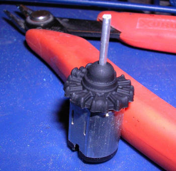 I
started by working on the mounting of the mini motor. The kit provides half the
engine- the first row of cylinders is attached to a backing plate fitting
snugly between the fuselage halves. It was a 5-minute dremel job to hollow out
room for the motor to fit tightly into the backing plate. After attaching an
extension rod of aluminum tubing over the moto
I
started by working on the mounting of the mini motor. The kit provides half the
engine- the first row of cylinders is attached to a backing plate fitting
snugly between the fuselage halves. It was a 5-minute dremel job to hollow out
room for the motor to fit tightly into the backing plate. After attaching an
extension rod of aluminum tubing over the moto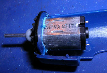 r shaft (allow plenty of extra
and don’t bend the tubing!) it was ready to be mounted. CA glue the motor to
the plate- then CA glue the painted plastic cylinders to the motor face. This
allows the proper clearance as if the motor was not even there.
r shaft (allow plenty of extra
and don’t bend the tubing!) it was ready to be mounted. CA glue the motor to
the plate- then CA glue the painted plastic cylinders to the motor face. This
allows the proper clearance as if the motor was not even there.
One thing to note: after every step, test the motor to make sure it is still working! And anytime you use CA glue near the motor, careful not to get any inside the motor of the shaft.
 Using old copper wire from a phone line, hook up the leads of the motor and
allow plenty of extra wire to go down the support tube and under the base for
hookup to the switch and battery pack.
Using old copper wire from a phone line, hook up the leads of the motor and
allow plenty of extra wire to go down the support tube and under the base for
hookup to the switch and battery pack.
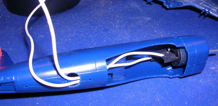
After the leads were attached, I drilled a mounting hole just aft of the wing section. When measured for a tight fit to the support tube, it was time to close the fuselage. I had hopes of including the interior and even tried my hand at painting up a pilot. But when I tried to attach the canopy- my pilot was too tall- so in frustration I yanked him out and decided to silver over the canopy.
 Wings were assembled easily and holes were drilled out for the rocket
attachment points. However, no rockets are in the kit! All I added was the
centerline fuel tank. Landing gear doors fit rather well in the closed
position, as did the tail wheel doors.
Wings were assembled easily and holes were drilled out for the rocket
attachment points. However, no rockets are in the kit! All I added was the
centerline fuel tank. Landing gear doors fit rather well in the closed
position, as did the tail wheel doors.
The nose cowling section was added next. After a little bit of putty and sanding, the airframe was ready to paint.
| COLORS & MARKINGS |
Very easy- overall Glossy Sea Blue! The Marines version I chose also had red wingtips, prop hub, and top of the tail. I used wet tissue stuffed into the nose to protect the painted engine face. Light scuffing of silver to show wear. Decals went on very nicely.
| CONSTRUCTION CONTINUES |
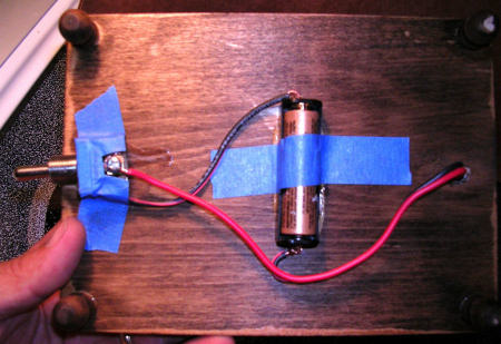 After paint was dry, I inserted my aluminum support tube, fed the wires down
through the tube, and CA glued it in place to provide strength. On the bottom
of the wood base, I had used Elmer’s glue to attach the battery pack and
switch. Next I drilled into my wood base, mounted on wood craft risers and
glued the model and tube into the wood base, feeding the wires down through
the base to the bottom for attachment to the switch and batteries.
After paint was dry, I inserted my aluminum support tube, fed the wires down
through the tube, and CA glued it in place to provide strength. On the bottom
of the wood base, I had used Elmer’s glue to attach the battery pack and
switch. Next I drilled into my wood base, mounted on wood craft risers and
glued the model and tube into the wood base, feeding the wires down through
the base to the bottom for attachment to the switch and batteries.
Hooking up the wires is easy and may take some reversing to make sure the prop spins in the right direction. Basically: one lead from batteries goes to switch, one lead from motor goes to switch. The other two leads go together. Don’t ask me which, just try the options until you get the switch to work. If prop spins in wrong direction, reverse the leads.
| CONCLUSIONS |
 When
all is ready- mount your prop. I had to wrap a small piece of tape around the
shaft to make a tight fit into the prop hub. A dab of CA glue attaches the
prop. Try to get it as balanced as you can! Luckily, this one came out dead
perfect and spins spot on!
When
all is ready- mount your prop. I had to wrap a small piece of tape around the
shaft to make a tight fit into the prop hub. A dab of CA glue attaches the
prop. Try to get it as balanced as you can! Luckily, this one came out dead
perfect and spins spot on!
I am hooked on these motors and my head spins with possibilities. The materials are very cheap and the presentation adds a new dimension to any prop model. It looks cool on my desk at work and even doubles as a cooling fan at times!
September 2006
| REFERENCES |
Copyright ModelingMadness.com. All rights reserved. No reproduction in part or in whole without express permission.
If you would like your product reviewed fairly and fairly quickly, please contact the editor or see other details in the Note to Contributors.