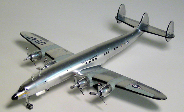
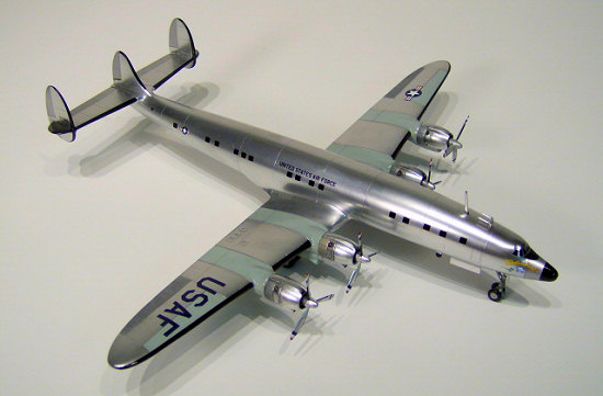
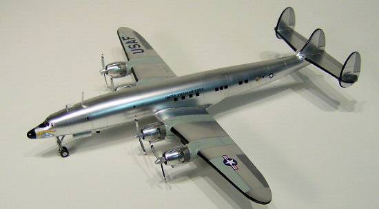
Minicraft 1/144 C-121E 'Columbine III'
| KIT #: | 14468 |
| PRICE: | $19.00 MSRP |
| DECALS: | Two Options |
| REVIEWER: | John Kauck |
| NOTES: |
| HISTORY |
Having used Lockheed Constellations has his personal transport while Supreme Commander Allied Powers Europe, Dwight D. Eisenhower continued to use the type when he became president in 1953, using a C-121A Lockheed Constellation dubbed Columbine II, named for the state flower of Colorado, his wife’s birthplace. The four-engine aircraft was a military version of the Lockheed 749 airliner.
 In 1954, Columbine III, a
C-121E Lockheed Super Constellation entered presidential service. Eighteen feet
longer than Columbine II with a cruising speed of 355 miles per hour, it served
as the Presidential aircraft until 1961 when President Eisenhower left office.
In 1954, Columbine III, a
C-121E Lockheed Super Constellation entered presidential service. Eighteen feet
longer than Columbine II with a cruising speed of 355 miles per hour, it served
as the Presidential aircraft until 1961 when President Eisenhower left office.
Columbine III became the first plane officially designated “Air Force One” due to a strange coincidence. After take-off from Washington Airport, an air traffic controller called on Columbine III by her USAF serial number. Seconds later, the pilot of a commercial airliner in the area with a matching flight number responded to the call as well. Shortly thereafter it was determined that any aircraft carrying the president, and only that aircraft, would be designated “Air Force One.”
Specifications:
Length: 116 ft 2 in (35.42 m)
Wingspan: 126 ft 2 in (38.47 m)
Tail Height: 24 ft 9 in (7.54 m)
Engines: Four Wright R-3350-DA3 Turbo Compound Supercharged @ 3,250 hp each
Maximum Takeoff Weight: 137,500 lbs
Maximum Range: 5,400 miles
Ceiling: 25,000 ft
Speed: 355 mph cruising; 380 mph maximum
| THE KIT |
Overall, I like Minicraft kits. The parts generally have minimal flash and fit together well. The kits are generally good, albeit simple, renditions of their subject aircraft, with no interiors.
Best of all, Minicraft has excellent decals. The subjects are well rendered. The decals are thick, unquestionably opaque, and hold up very well under Micro Sol solution making it easy to get them to nestle down into and around complex curves.
I also
like the fact that Minicraft 1/144 cabin windows are usually represented with
black decals rather than molded in. It’s just easier sliding decals than
dealing with all those clear parts and masking, etc. But I find it curious that
the cockpit windows on  Minicraft
kits are usually molded clear, as they are on this kit. However, this kit did
provides a black cockpit window decal, (although it needs to be altered for the
Columbine) to enable you to black out the cockpit windows to match the rest of
the plane, which I did.
Minicraft
kits are usually molded clear, as they are on this kit. However, this kit did
provides a black cockpit window decal, (although it needs to be altered for the
Columbine) to enable you to black out the cockpit windows to match the rest of
the plane, which I did.
The instructions are thorough – two pages containing eight diagrams, noting when and when not to glue, and indicating right next to the drawing what colors small parts or assemblies should be painted. The third page on the back has a very good painting/decal diagram for both sides and the top of the aircraft, with a diagram for the bottom of the aircraft on the front page.
It’s best to always check references for proper markings as painting/decal diagrams may have minor inaccuracies or options, as did this one. (My references showed the optional insignia does go behind the left rear door.) Most of the time simply typing in the designation, i.e., “C-121E,” or nickname, i.e., “Columbine III” or “Air Force One,” of the aircraft into Google Images will find plenty of reference pictures, as it did with this aircraft. (Be careful to use consistent pictures, as this plane’s paint scheme had minor changes over the years.)
The kit has three blue plastic parts sprues and a single clear part, the cockpit windshield/roof. One plastic sprue contains the left and right fuselage halves and the left and right upper wing halves. The second contains just the lower wing half. The third contains all the other smaller parts to construct the engines, landing gear, gear doors, and rear wings, etc. Again, some had minor flash to be lightly sanded, but nothing out of the ordinary.
| CONSTRUCTION |
After first gluing a good size fishing weight into the nose cavity so the finished plane will sit properly on its tri-landing gear, the two fuselage halves, with the forward gear bay ceiling part #62 in between, went together very well and were easily bonded with a few touches of Zap CA super thin glue. I clamped the two halves together then applied the Zap and let capillary action draw it along the seam.
Unlike in the instructions, I preferred to complete the entire fuselage first, so the clear cockpit window/roof section was attached next with thick super glue, and then sanded to get the surfaces to align after first covering the windshield frame lines with masking tape to preserve the scribed surface detail.
The next thing to be done on the fuselage was to fill the factory scribed front and rear passenger doors on the model with thick super glue. They are not properly shaped or placed and are way too thick for this scale. Furthermore, decals are provided to simulate the doors anyway.
 Note:
this plane has a bare metal exterior which means a silver or metallic
paint finish. These finishes reveal any imperfections which are even more
noticeable at small scales like 1/144. I use Flex.i.File sanding sticks,
working down to and including the #3210 Polisher/Finisher to a very smooth
finish. I then draw a Metallic Silver Sharpie marker along the seams to reveal
any tiny gaps requiring extra attention with super glue and more sanding.
Note:
this plane has a bare metal exterior which means a silver or metallic
paint finish. These finishes reveal any imperfections which are even more
noticeable at small scales like 1/144. I use Flex.i.File sanding sticks,
working down to and including the #3210 Polisher/Finisher to a very smooth
finish. I then draw a Metallic Silver Sharpie marker along the seams to reveal
any tiny gaps requiring extra attention with super glue and more sanding.
My references (and the instructions) showed some prominent panel lines all the way around the fuselage. Using my dividers, I determined their placement from my references as best I could and scribed them with my #11 blade.
Next came the front wings. After dry-fitting to check the fit, I decided to put the front wing bottom on the fuselage first with thick super glue. Then I attached the upper wing halves to the bottom of the wing and to the plane on each side where I used thick super glue to attach them to the wing roots and fill the minor gaps at the same time which I subsequently sanded smooth on both top and bottom.
The rear wing section is molded as four pieces; two horizontal wings each with a vertical tail fin attached via a cross joint. First I attached the horizontal wings to the plane with a few touches of Zap CA super thin glue, taking care that they are exactly perpendicular to the center tail fin. I then attached the outer vertical fins to them again taking care that they are exactly perpendicular to the wings and parallel to the center tail fin.
Next, I cut and cleaned up all the engine parts and propeller parts. The engine cowlings are molded in two halves with the engine cylinders molded as a third piece to be set inside. To achieve smooth round seams where the two engine halves meet both inside and outside, I glued them together and filled any gaps with thick super glue, then sanded the outside and twisted progressively finer grit small rolled sandpaper sheets back and forth inside the cowling until the seams disappeared under my silver pen. After dry-fitting, I then inserted the cylinder part from the back with thin super glue. Then I dry fit all the engines and propellers to each other and to the aircraft and left the engines and propellers off for painting separately and attachment later.
I cut and cleaned the landing gear pieces, tire/hubs, and gear doors. Then I dry fit them to each other and to the aircraft and left these pieces off the aircraft for painting separately and attachment later.
Detailing:
My references showed several prominent antennae on the plane. I took a horseshoe antenna from another 1/144 kit. I scratch built the large antenna mast behind the horseshoe, as well as the two rectangular “fin” antennae behind the front landing gear bay from sheet styrene stock. I attached all the antennae with droplets of super glue. (See my technique in the final assembly section below.)
Finishing and Painting:
For the
bare metal finish I decided to use the Alclad ll metal painting system. For
those not familiar, the Alclad system consists of a black primer coat, which
dries as smooth as glass, over which the metallic carrier coats are sprayed.
While the primer requires at 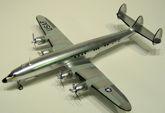 least
24 hours to cure, the subsequent metallic carrier coat(s) dries within a half
hour and then may be masked and painted over if needed.
least
24 hours to cure, the subsequent metallic carrier coat(s) dries within a half
hour and then may be masked and painted over if needed.
I made a makeshift handle out of a coat hanger by cutting it on each side of the hook, then twisting masking tape around each of the three “prongs” and bending them to fit into each of the three landing gear openings. This allowed me to prime, paint and hang to dry without ever having to touch or set the plane down. I then Alclad primed the entire plane and the landing gear, engines, propellers, and antennae.
With the primer fully cured, I used Alclad #105 Polished Aluminum on the entire plane, landing gear, engines, antennae, and propellers. I used #112 Steal on the engine cylinders and engine cowlings behind the exhausts as per my references. I then masked a section of the nose as per my references and used #119 Airframe Aluminum on it.
I used enamels on the rest of the parts. I masked and then used Testors #1146 Silver on the control surfaces of the wings and tail. I then masked the sections behind the engines on both the top and bottom of the front wing and airbrushed them with Model Master FS# 16473 Aircraft Gray. (The instructions diagrams were accurate per my references.) I also used this gray on the front landing gear doors and on the lower halves of the propeller blades. I used Testors enamel #1149 Flat Black on the tires and on the tip of the nose.
| FINAL CONSTRUCTION |
First, I attached the four engines to the plane. Next, I assembled and attached the landing gear, struts, and gear doors. Doing so with just a tiny drop of super glue is an extremely delicate task. Precise placement of these often tiny parts without unsightly gobs of glue is always difficult at the 1/144 and smaller scales. For this reason I find the use of a “third hand” indispensable. Available at most hobby shops and on-line, it is a small stand with a heavy iron base and one or more ball joint mounted arms with alligator-type spring clamps to hold a part in any angle required. I use them in combination with plastic hemostats (i.e., scissor clamps,) so as not to scratch the part, to position and then hold these small parts in place while the super glue dries, as using super glue accelerant may mare the finish and maybe even dissolve surrounding paint.
| COLORS & MARKINGS |
Before I did anything else, I made several actual size (1/1) copies of the decal sheet to use as decal placement templates. This is one of my rules of thumb and I highly recommend it, especially on this kit.
I started with the black “ice boot” decals on the leading edges of the wings and tail fins. My references also showed that they were not thick enough and/or didn’t extend far enough in many spots, especially on the tail, the leading edges of which should be entirely covered. I made all the required adjustments with some black stripe decals and black stock decal as necessary. They required the use of a lot of red Micro Sol setting solution to get the decals to conform to the complex curves properly, especially on the tail fins.
 As mentioned, the kit provided
black decals for the windows connected by clear carrier film to each other.
Similar to minor gaps and scratches, the carrier film would be rather unsightly
and stand out on the bare metal finish at this small scale. Therefore, with a
sharp new #11 blade, I removed all the window decals from the carrier film and
trimmed it from around the rest of the decals, trimming as close to the “United
States Air Force,” the tail numbers, and the doors as possible while leaving
them intact (letters or numbers connected and clear film still “inside” the
doors.)
As mentioned, the kit provided
black decals for the windows connected by clear carrier film to each other.
Similar to minor gaps and scratches, the carrier film would be rather unsightly
and stand out on the bare metal finish at this small scale. Therefore, with a
sharp new #11 blade, I removed all the window decals from the carrier film and
trimmed it from around the rest of the decals, trimming as close to the “United
States Air Force,” the tail numbers, and the doors as possible while leaving
them intact (letters or numbers connected and clear film still “inside” the
doors.)
All this trimming makes decal placement a bit challenging. To get the placement of the cabin windows, doors, and insignias correct, for each side respectively, I cut out the copy of the entire side decal from my 1/1 decal copy. Using the wing and the previously scribed cabin panel lines to align it, I taped the copy above the fuselage to the tail on one end and at the bottom to the fuselage on the other. I then floated and placed each window individually onto the fuselage using my decal copy template above as a guide for the exact location of each window, insignia, door, and “United States Air Force.” This yields a great looking result with little or no carrier film anywhere on the bare metal surface.
Next, I placed the tail numbers on outside of each outer tail fin. On the front wings, I did trim the clear carrier film from around/inside each letter in the “USAF” and then again using the decal copy as a template, I placed each USAF and the insignias on the top and bottom of the appropriate front wings as instructed.
The cockpit window decals provided were incorrect for the VC-121E. There are only seven windows around the cockpit. I separated all these windows, then removed the smaller side windows, second from each end, then placed the remaining window decals around the cockpit per my references.
I finished decaling with the propellers. The red, white, & blue tip decals took a lot of red Micro Sol to get the front and back decals to join together and nestle down around the blade tips. Finally, my references showed that the leading edges of each propeller blade have a black leading edge. I imitated this with black stripe decal with lots of Micro Sol on each blade.
After letting the decals dry over night I gave the entire model a coat of Future to give it a gloss finish. I then “weathered” the engines a bit with a “wash” of black paint and thinner. I then set in the propellers.
| REFERENCES |
· Planes of the Presidents: An Illustrated History of Air Force One; Bill Holder; Schiffer Military History Books, Atglen, PA, 2000
· Various web sites for reference photos, generated by search engine entries on the plane’s military designation, callsign, and/or nick name, i.e., “C-121E” and/or “Columbine III” into Google Images and scroll through the results. Save the photos (right click on them and click “save photo as”) to your hard drive, then just zoom in on the area you want.
| CONCLUSIONS |
 FYI, this was the fourth kit
in a little theme build I’ve done of the history of presidential aircraft, of a
total of eight planes and one helicopter. (See my other reviews of
Presidential/VIP Aircraft.) (Editor's Note: Many of these later planes can be
seen at the USAF museum.)
FYI, this was the fourth kit
in a little theme build I’ve done of the history of presidential aircraft, of a
total of eight planes and one helicopter. (See my other reviews of
Presidential/VIP Aircraft.) (Editor's Note: Many of these later planes can be
seen at the USAF museum.)
I
enjoyed the kit. First, the historical subject matter makes it interesting.
While it’s a fairy easy plane to build, a flawlessly smooth bare metal finish
and the decals can be challenging. This would be a good challenge/practice for
beginners. As an intermediate modeler, I found it a lot of fun and the most
satisfying of all eight presidential/VIP transports I built. (The Connie is just
a beautiful, elegant plane!) I’m sure experts would enjoy it as well.
Happy Modeling!
December 2007
Copyright ModelingMadness.com
If you would like your product reviewed fairly and quickly, please contact the editor or see other details in the Note to Contributors.