Pilot Replica 1/48 Saab J.29B
| KIT #: | 48A004 |
| PRICE: | $46.00 |
| DECALS: | Three options |
| REVIEWER: | Robert Hart |
| NOTES: |
| HISTORY |
 The SAAB J29
was a Swedish single-engine jet-powered fighter aircraft developed by Svenska
Aeroplan Aktiebolaget (SAAB) at the directive of the Swedish Air Force. The
prototype first flew on September 1, 1948. The aircraft was delivered in
versions A, B, C, D, E, and F and saw military service with Sweden and Austria
from 1951 through the early 1970s. Despite the airplane's decidedly rotund
appearance ( it was nicknamed Tunnan (barrel)) , it was fast and nimble and
examples were used to set multiple international speed records in the early
1950s. Unfortunately, and in common with most other early jet fighters, the J29
had a high accident rate.
The SAAB J29
was a Swedish single-engine jet-powered fighter aircraft developed by Svenska
Aeroplan Aktiebolaget (SAAB) at the directive of the Swedish Air Force. The
prototype first flew on September 1, 1948. The aircraft was delivered in
versions A, B, C, D, E, and F and saw military service with Sweden and Austria
from 1951 through the early 1970s. Despite the airplane's decidedly rotund
appearance ( it was nicknamed Tunnan (barrel)) , it was fast and nimble and
examples were used to set multiple international speed records in the early
1950s. Unfortunately, and in common with most other early jet fighters, the J29
had a high accident rate.
The type's only combat use came during the Congo Crisis in the early 1960s. The crisis was a period of power struggles and severe unrest that began when Congo was declared independent from Belgium. Internecine fighting began almost immediately as the province of Katanga wanted its own independence as the State of Katanga. The degree of disquiet led to the Congolese government to ask the United Nations to send in UN troops for assistance in ending the fighting. In response to a request from the UN, Sweden sent 9 J29s and 2 S29s (reconnaissance version of the J 29) to Leopoldville in the Congo where the detachment became known as United Nations Fighter Squadron Number 22. The J29s were initially tasked with escorting UN transport aircraft and defending against attacks from Katangese aircraft, but soon went on the offense by attacking Katangese airfields and ground targets. By January 1963 the fighting had largely ceased. Two J29s and two S29s were flown back to Sweden. The rest were destroyed on site as they were no longer needed due to newer aircraft becoming available.
| THE KIT |
The kit has 90 parts
molded in light gray styrene, eight parts molded in clear styrene, and eight
photo-etched brass parts. A four page instruction sheet illustrates 19 assembly
steps. A separate four page sheet provides full color painting and decal
placement guides. Color call outs are referenced to Tamiya, FS595, Humbrol, and
Vallejo. The photo-etched parts provide seat belts, shoulder harnesses, and rear
view mirrors. The clear parts include the separately molded canopy and
windshield, the lenses for the landing lights, and the covers for the wing tip
position lights. The flaps, slats, air brakes, and ailerons are all molded
separately. The surface detail is a mix of engraved panel lines, recessed rivets
and fasteners, and raised areas representing access panels/hatches, etc. The
three decal options provided are all for UN Fighter Squadron Number 22 J29s. The
kit has a high level of detail and, in common with most other recently tooled
kits, has a high parts count with many sub-assemblies comprised of multiple
separate parts. Although, I tend to prefer high detail/high parts count kits,
this kit's parts breakdown made assembly very ted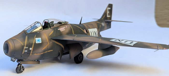 ious
and increased the chances of having alignment issues. For example: all three
landing gear legs have separate upper and lower torque links, The torque links
have to be attached to each other at tiny contact points and then attached to
the landing gear legs. The kit's fuselage assembly also has some overly complex
engineering. The fuselage is divided into forward and rear sections broken at
the transport joint. The rear section is split vertically and incorporates the
vertical tail. The forward section is also split vertically, but then is divided
quarterly along the horizontal axis. The forward fuselage also has some separate
panels that appear to have been for access to the cannons. However, the kit does
not provide anything to go behind the panels, so, unless the builder fabricates
some bays and equipment, the panels will need to be attached in the closed
position. Further complicating the forward fuselage assembly is the need to trap
the cockpit tub and the nose and main landing gear bays inside when the six
parts that form the exterior shell are joined. In the review kit, one of the
forward fuselage quarters was warped. I considered returning it to Pilot
Replicas for replacement, but I was unable to find any contact information in
the kit or on their website and ended up working around the warp by clamping and
gluing during assembly.
ious
and increased the chances of having alignment issues. For example: all three
landing gear legs have separate upper and lower torque links, The torque links
have to be attached to each other at tiny contact points and then attached to
the landing gear legs. The kit's fuselage assembly also has some overly complex
engineering. The fuselage is divided into forward and rear sections broken at
the transport joint. The rear section is split vertically and incorporates the
vertical tail. The forward section is also split vertically, but then is divided
quarterly along the horizontal axis. The forward fuselage also has some separate
panels that appear to have been for access to the cannons. However, the kit does
not provide anything to go behind the panels, so, unless the builder fabricates
some bays and equipment, the panels will need to be attached in the closed
position. Further complicating the forward fuselage assembly is the need to trap
the cockpit tub and the nose and main landing gear bays inside when the six
parts that form the exterior shell are joined. In the review kit, one of the
forward fuselage quarters was warped. I considered returning it to Pilot
Replicas for replacement, but I was unable to find any contact information in
the kit or on their website and ended up working around the warp by clamping and
gluing during assembly.
| CONSTRUCTION |
Pilot Replicas offers a number of aftermarket accessories for this kit and I used some of them. I also used aftermarket accessories from other manufacturers. These include: Aires 4725 SAAB J 29 Tunnan Cockpit set, Quickboost QB 48 967 SSAAB J29 Tunnan Front Landing lights, Maestro Models MMK 4940 SAAB J29 Tunnan masking set, Master Models AM 48-071 SAAB 29 Tunnan Pitot Tubes, and from Pilot Replicas; 484007 Drop tanks without fins, 48R008 Seamless Jet Intake, 484015 Nose and main wheels set, plus 48R013 Tow Bar
I also used a couple of 1 mm AK Interactive white lenses. Note: none of these aftermarket parts were essential to building the review model. I happen to enjoy using aftermarket parts and in most cases they add additional detail and/or ease the building process.
I started construction by
running a scriber through all of the recessed panel lines. I do this on all of
my builds to facilitate the oil paint pin wash applied later in the
painting/finishing process. The next step was to test fit the one piece Aires
cockpit floor and rear bulkhead with the upper forward fuselage walls.
Surprisingly, the fit wasn't too bad and I only had to sand off about .5 mm from
the edges of the floor and bulkhead. However, test fitting of the lower fuselage
walls revealed the need for the thickness of the underside of the cockpit floor
to be reduced by about 1.5 mm. Once I was satisfied that the cockpit would fit
inside the fuselage, the rest of the cockpit was assembled per the Aires
instructions with one exception. Both the kit and the Aires set provide
photo-etched seat belts and harnesses. I'm not a fan of bending and attaching
photo-etched seat belts to conform to irregularly shaped ejection seats, then
painting the belts, and picking out the tiny buckles and hardware with 10/0
paintbrushes. Instead, I cut the buckles and hardware off of the Aires belts,
made new belts from tissue paper colored with a green Sharpie, and attached the
home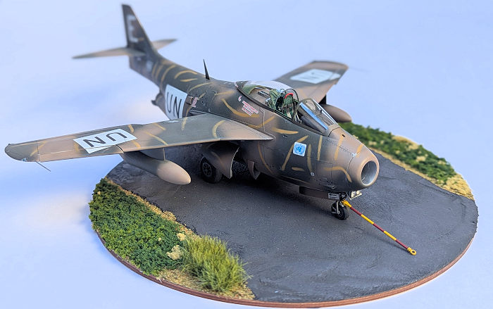 made
belts to the Aires buckles. The paper belts folded over the ejection seats much
more realistically than any photo-etched belt could and were closer in scale
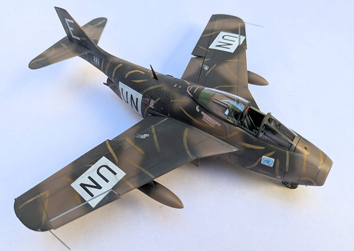
thickness to boot. I painted the cockpit (including the instrument panel) with a
50/50 mix of Tamiya acrylic XF61 Deep Green and Tamiya XF71 Cockpit Green. I
picked out the various knobs, buttons, levers, switches, and panels with red,
black, silver, and white per color photos that I found on the internet.
made
belts to the Aires buckles. The paper belts folded over the ejection seats much
more realistically than any photo-etched belt could and were closer in scale
thickness to boot. I painted the cockpit (including the instrument panel) with a
50/50 mix of Tamiya acrylic XF61 Deep Green and Tamiya XF71 Cockpit Green. I
picked out the various knobs, buttons, levers, switches, and panels with red,
black, silver, and white per color photos that I found on the internet.
Before installing the cockpit and closing the forward fuselage, the main landing gear bays need to be attached to the fuselage sides. Ordinarily, this would be a simple task, but the previously mentioned warped forward fuselage quarter caused a need for much test fitting, copious amounts of superglue, and the biggest clamp in my tool set. Even with the bay securely in place, the warp was not entirely eliminated, and when all of the forward fuselage parts were joined, it caused a discernible step. In fact, none of the forward fuselage parts fit very well. I had to thin the sidewalls of the nose landing gear bay to get the lower fuselage quarters to close around it and all of the separately molded hatches left sizeable gaps and steps where they joined the fuselage. The gaps were too large to pass off as panel lines and I ended up filling them with superglue, sanding smooth, and re-scribing the panel lines. Likewise, the lower forward fuselage half left big steps where it joined the upper half. The step on one side was so big that I sanded clear through the part trying to get the mating surfaces flush. More filling, sanding, and re-scribing followed. With the forward fuselage more or less in one piece, I filled the remaining space around the periphery of the inside of the forward fuselage with 1 ½ ounces of pewter scraps from some metal model car kits. I then test fitted the aftermarket seamless intake to the fuselage. It would not clear the cockpit floor. By carefully sanding down the fairly thick wall of the intake I was able to reduce the outer diameter to where it no longer fouled the cockpit floor. After the intake was in place, I sanded down all of the seams on the forward fuselage and re-scribed any panel lines that had been eradicated. The forward most piece of the jet pipe has to be trapped between the halves of the rear fuselage before they are joined. Once the jet pipe was installed, the rear fuselage halves were glued to each other, the seams were sanded smooth, and the panel lines were re-scribed. The forward and aft fuselage halves are attached to each other at the location of the real aircraft's transport joint The aft fuselage has a raised flange that runs around the circumference of its forward edge and the aft edge of the forward fuselage half has a groove running around its circumference. This appeared to make for an easy join of the front and rear fuselage sections, but when the parts were mated, they had different cross sections which caused big steps at the attachment points. Since this joint was on a prominent panel line of the real aircraft and there was raised detail adjacent to the panel line, I didn't want to fill, sand, and then replace eradicated detail to eliminate the steps. Instead, I used a micro chisel to deepen the groove on the front fuselage section and reduce the depth of the flange on the rear fuselage section. After I was able to get the two sections to mate without steps and with a gap that would pass as a panel line, I glued them together with medium curing superglue and applied a big clamp to maintain the now matching cross sections. The fuselage was largely complete at this point.
The flaps, ailerons, and slats are molded in upper and lower halves. They assembled without issues. The ailerons are designed to operate. I'm not a fan of working parts on my models and I cut off the parts of the hinges that enable the movement of the ailerons. The wings are also molded in upper and lower halves and assembly was without issues. The wings join the fuselage by tongues and grooves and, although the fit wasn't bad, there were still gaps that had to be filled, sanded, and eradicated detail restored. The horizontal tail plane is molded in one piece and fits into a groove at the base of the vertical tail plane. The fit here was very good and no filler was required. Each wingtip has formation lights on the leading and trailing edges. The lights on the leading edges have colored bulbs and transparent covers. One of the covers was missing from the review kit and I made a replacement from a length of the kit's clear parts sprue tree. The airframe was now complete and it was time for paint and decals.
| COLORS & MARKINGS |
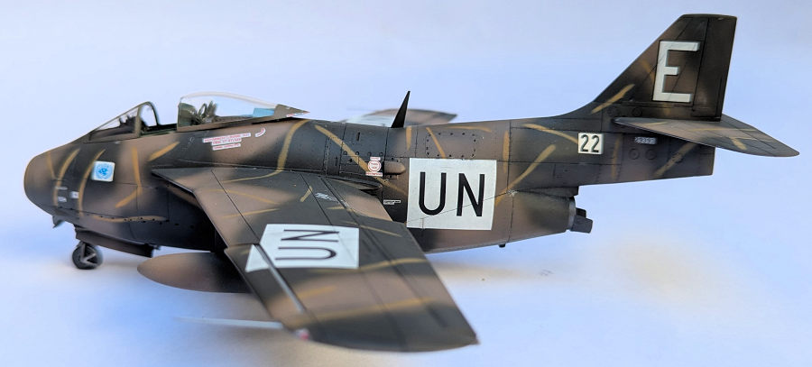
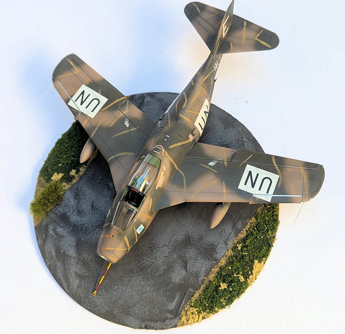 The kit
provides three decal options. Two are for mostly natural metal aircraft and one
is for an aircraft in a field applied camouflage. I decided to go with the
camouflaged machine. The topside camouflage is a brown and green segmented
pattern with randomly applied orangey tan stripes. The colors appear to have
been sprayed freehand and there is very evident over spray. The underside was
left in natural metal. I first sprayed a coat of Tamiya gray lacquer primer.
After the primer was dry, I buffed it with a 4000 grit micromesh cloth. I then
sprayed a coat of Tamiya gloss black lacquer on the areas that would have a
natural metal finish. I used Alclad II Aluminum as the base finish and masked
off and sprayed various panels with Alcald II Dark Aluminum, and White Aluminum
to simulate a natural metal finish. Pilot Replicas provides FS595 approximations
of the three camouflage colors, but I decided to use my own interpretations. I
used Green Drab and Pale Brown from Hataka's Orange Line (lacquer) Modern
Swedish AF Paint Set Vol.1. For the stripes I used a 50/50 mix of Tamiya Acrylic
Orange X6 and Tamiya Acrylic XF59 Desert Yellow. In retrospect, the Pale Brown
looks a little too light and too pink . If I was to build the model again, I
would shoot for something closer to WWII RAF dark earth to approximate the brown
on the real aircraft. I sprayed the model with a coat of Tamiya X22 Clear and
applied the decals. I had to carefully measure and slice the “UN” insignias on a
diagonal where they crossed the slat's and flap's intersections with the wings,
but otherwise, the decals worked perfectly. One nice touch was that the kit came
with two sets of stencil decals, one set with clear backgrounds for the NMF
decal options and another set for the camouflaged aircraft with silver
backgrounds to simulate where the camo had been painted around the stencils.
When the decals had dried, I applied a Paynes Gray oil paint pin wash to the
panel lines and other recessed details. I let the oil paint dry for about 48
hours and then gave the model a coat of of Tamiya Acrylic XF86 Flat Clear.
The kit
provides three decal options. Two are for mostly natural metal aircraft and one
is for an aircraft in a field applied camouflage. I decided to go with the
camouflaged machine. The topside camouflage is a brown and green segmented
pattern with randomly applied orangey tan stripes. The colors appear to have
been sprayed freehand and there is very evident over spray. The underside was
left in natural metal. I first sprayed a coat of Tamiya gray lacquer primer.
After the primer was dry, I buffed it with a 4000 grit micromesh cloth. I then
sprayed a coat of Tamiya gloss black lacquer on the areas that would have a
natural metal finish. I used Alclad II Aluminum as the base finish and masked
off and sprayed various panels with Alcald II Dark Aluminum, and White Aluminum
to simulate a natural metal finish. Pilot Replicas provides FS595 approximations
of the three camouflage colors, but I decided to use my own interpretations. I
used Green Drab and Pale Brown from Hataka's Orange Line (lacquer) Modern
Swedish AF Paint Set Vol.1. For the stripes I used a 50/50 mix of Tamiya Acrylic
Orange X6 and Tamiya Acrylic XF59 Desert Yellow. In retrospect, the Pale Brown
looks a little too light and too pink . If I was to build the model again, I
would shoot for something closer to WWII RAF dark earth to approximate the brown
on the real aircraft. I sprayed the model with a coat of Tamiya X22 Clear and
applied the decals. I had to carefully measure and slice the “UN” insignias on a
diagonal where they crossed the slat's and flap's intersections with the wings,
but otherwise, the decals worked perfectly. One nice touch was that the kit came
with two sets of stencil decals, one set with clear backgrounds for the NMF
decal options and another set for the camouflaged aircraft with silver
backgrounds to simulate where the camo had been painted around the stencils.
When the decals had dried, I applied a Paynes Gray oil paint pin wash to the
panel lines and other recessed details. I let the oil paint dry for about 48
hours and then gave the model a coat of of Tamiya Acrylic XF86 Flat Clear.
| FINAL PARTS |
I wanted to use the Pilot
Replica's aftermarket main and nose wheel set. I assumed that the wheels would
simply be straight across replacements for the kit parts. They are not. The
aftermarket set includes an all new pair of resin main gear legs that differ
from the kit's main gear legs. The kit's legs have the brake rotors molded onto
the legs themselves, but the aftermarket set has the rotors cast onto the
wheels. I didn't want to use the resin gear legs as I had learned from previous
experience that they buckle over time. So, I sanded the rotors off of the kit's
plastic gear legs and drilled out the center of the aftermarket wheels until I
was satisfied with the fit and alignment. The nose landing gear is comprised of
a two piece mud guard, a leg, two torque lengths, and the nose wheel/tire. All
of the contact points in this assembly are tiny and I was concerned about its
ability to support the already heavy model. I ended up drilling into about ½ the
length of the gear leg, through the mud guard and into about ½ the diameter of
the nose wheel to inse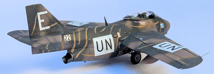 rt
a steel pin. Even with the extra support, the nose landing gear is kind of
wiggly and flexible when the model's weight is on it. I then added the main
landing gear, gear bay doors, and the torque links. The tail pipe has a “sugar
scoop” fairing at its aft end. The fairing in the kit had a radius that did not
match the radius of the tail pipe. I clamped the fairing around a wooden dowel
that had the same diameter as the tail pipe and held it in the steam of a
boiling teapot for about 30 seconds. It took two of the steam treatments before
it fit the tail pipe properly. I finished up adding the ancillary details to the
underside of the model by attaching the drop tanks, nose landing gear bay doors,
and the landing lights. Turning the model over, I attached the main instrument
panel and gun sight to the cockpit coaming before gluing the whole assembly to
the fuselage just forward of the cockpit opening. The canopy guide rails were
attached to each side of the cockpit and the canopy opening/closing mechanism
was glued to the turtle deck. The ejection seat was a very tight fit and I was
concerned that it might need to be cut down, but with some determined effort
(and a few curse words), it finally settled into place. The kit provides 3 rear
view mirrors on the photo-etched set, one on the bow of the windshield and two
on the bow of the canopy. I could only find photos showing the one mirror on the
canopy bow and I used a mirror from an Eduard set that has mirror finished
photo-etched parts. I could not find any photos showing J29s with slats, flaps,
or air brakes actuated, but because the kit provided them as separate parts, I
decided to finish the model with the slats and flaps partially down and the air
brakes open (they actually fit well in the closed position). The model was
completed with the addition of the canopy, windshield, the dorsal antenna, the
pitot tubes, and the tiny position light lenses on the aft ends of the wingtips.
rt
a steel pin. Even with the extra support, the nose landing gear is kind of
wiggly and flexible when the model's weight is on it. I then added the main
landing gear, gear bay doors, and the torque links. The tail pipe has a “sugar
scoop” fairing at its aft end. The fairing in the kit had a radius that did not
match the radius of the tail pipe. I clamped the fairing around a wooden dowel
that had the same diameter as the tail pipe and held it in the steam of a
boiling teapot for about 30 seconds. It took two of the steam treatments before
it fit the tail pipe properly. I finished up adding the ancillary details to the
underside of the model by attaching the drop tanks, nose landing gear bay doors,
and the landing lights. Turning the model over, I attached the main instrument
panel and gun sight to the cockpit coaming before gluing the whole assembly to
the fuselage just forward of the cockpit opening. The canopy guide rails were
attached to each side of the cockpit and the canopy opening/closing mechanism
was glued to the turtle deck. The ejection seat was a very tight fit and I was
concerned that it might need to be cut down, but with some determined effort
(and a few curse words), it finally settled into place. The kit provides 3 rear
view mirrors on the photo-etched set, one on the bow of the windshield and two
on the bow of the canopy. I could only find photos showing the one mirror on the
canopy bow and I used a mirror from an Eduard set that has mirror finished
photo-etched parts. I could not find any photos showing J29s with slats, flaps,
or air brakes actuated, but because the kit provided them as separate parts, I
decided to finish the model with the slats and flaps partially down and the air
brakes open (they actually fit well in the closed position). The model was
completed with the addition of the canopy, windshield, the dorsal antenna, the
pitot tubes, and the tiny position light lenses on the aft ends of the wingtips.
| CONCLUSIONS |
I have mixed feelings about this kit. It is nicely detailed, has exquisite surface detail, and excellent decals. On the down side, the distinctly odd engineering of the forward fuselage caused unpleasant fit issues. I estimate that I spent about 25% of the total time it took to build the model dealing with the fit issues on the forward fuselage. I also thought that the differences between the kit's landing gear and the aftermarket landing gear were puzzling given that they were both made by the same manufacturer. I think this kit is probably the best 1/48 J29 on the market, but I wish it had been easier to build.
26 November 2024
Copyright ModelingMadness.com.
All rights reserved. No reproduction in part or in whole without express
permission from the editor. If you would like your product reviewed fairly and fairly quickly, please
contact the editor
or see other details in the
Note to
Contributors. Back to the Main Page
Back to the Review
Index Page
Back to the Previews Index Page