Airfix 1/48 Vampire F.3
| KIT #: | A06107 |
| PRICE: | $35.00 |
| DECALS: | Three options |
| REVIEWER: | John Summerford |
| NOTES: | No photo etch |
| HISTORY |
Courtesy BAE systems
 The success
of the Gloster Meteor led to the De Havilland Aircraft Company being approached
to design and build an airframe for the Halford H1 turbojet engine (later to
become the DH Goblin). Initially designated DH99 (named the ‘Spider Crab’), it
was an all-metal design which was hugely experimental in its unorthodox
arrangement of twin rear booms mounted behind a molded, egg-shaped wood/aluminum
fuselage and one single engine. Further modifications resulted in the design
re-designated as the DH100 Vampire.
The success
of the Gloster Meteor led to the De Havilland Aircraft Company being approached
to design and build an airframe for the Halford H1 turbojet engine (later to
become the DH Goblin). Initially designated DH99 (named the ‘Spider Crab’), it
was an all-metal design which was hugely experimental in its unorthodox
arrangement of twin rear booms mounted behind a molded, egg-shaped wood/aluminum
fuselage and one single engine. Further modifications resulted in the design
re-designated as the DH100 Vampire.
The prototype DH100 Vampire (LZ548/G) was first flown on 20th September 1943 at Hatfield by Geoffrey R de Havilland (son of the founder), 6 months after the Meteor, due to delayed by engine availability.
The first production DH Vampire (F.1) was produced by the English Electric Company at Warton due to the production pressures and a lack of capacity at Hatfield. Despite finally arriving after the end of the Second World War, the DH Vampire was eagerly awaited and became the second British jet fighter to see service with the RAF. It was also given the honor of leading the VE - Day fly-past over London. It was the first RAF aircraft to be able to exceed 500.
The main production version was to be the DH Vampire FB.5 fighter bomber (a modified DH Vampire F.3) and this variant was also be the basis for many of the export versions. Separate night fighter and trainer models were produced as the DH113 Vampire NF and DH115 Vampire Trainer respectively.
A number of DH100 Vampires were also modified for shipboard use such as the De Havilland DH Sea Vampire and on 3rd December 1945, Captain Eric 'Winkle' Brown completed the first successful landing and take-off of a jet fighter from the Carrier HMS Ocean. Subsequently, it became the Royal Navy’s first jet fighter.
 The type
was very successful in the export market, providing many air forces with their
first experience of jet fighter operations and around 30 air forces were
ultimately to operate the type. Some fifty DH100 Vampire F1, F2 and FB variants
were purchased by the Royal Australian Air Force in 1946 and, although the
majority were built with Goblin engines, the second aircraft was built with a
Rolls-Royce Nene power-plant.
The type
was very successful in the export market, providing many air forces with their
first experience of jet fighter operations and around 30 air forces were
ultimately to operate the type. Some fifty DH100 Vampire F1, F2 and FB variants
were purchased by the Royal Australian Air Force in 1946 and, although the
majority were built with Goblin engines, the second aircraft was built with a
Rolls-Royce Nene power-plant.
By the time production finally ended, 3,269 Vampires had been built in England and a further 1,067 built under license abroad. The DH Vampire remained as a front-line fighter for the RAF until 1953, after which it was retained only in the pilot training and refresher role.
Elsewhere, the aircraft had surprisingly longevity with large numbers still in service in several air forces in the 1980s. The Swiss Air Force was the last Vampire user, retiring their sizeable fleet of DH Vampire FB.6s and T.55s from active service as late as 1990 It was finally retired from RAF service in 1966, being replaced by the Hawker Hunter and Gloster Javelin.
DH Vampire F.3 version had a production run of two prototypes and 202 airframes. It featured revised tail surfaces of a more ‘De Havilland’ shape; tailplane chord increased. Maximum weight increased to 11,970 lb. and flown 4 November 1946. 20 were exported to Norway and 86 aircraft sold to Canada.
| THE KIT |
A single bag holds four light gray sprues and the clear parts are in their own bag within the primary bag. The parts are well molded with crisp detail, no flash, and seams almost nonexistent. Wheel well detail is molded into the upper wing. In this example, there is a sink mark in fillet at the trailing edge of the right wing and fuselage. There is just enough texture on the surface to soften the sheen of the plastic.
The wings trap two spars. The front spar incorporates the first compressor face of the engine and the aft face of the main landing gear wells with the aft spar having the engine turbine and hinge plates for the flaps. The intakes are single pieces and have the vanes molded in. Three come with the kit, the oddball intended for the FB.9 version. The booms are keyed to aid assembly
 Total parts
count, including the clear parts is 124. Options are included for a seat for a
pilot figure, or one without that has a harness molded in, two instrument
panels, external underwing fuel tanks, and flaps posed completely down or up.
Total parts
count, including the clear parts is 124. Options are included for a seat for a
pilot figure, or one without that has a harness molded in, two instrument
panels, external underwing fuel tanks, and flaps posed completely down or up.
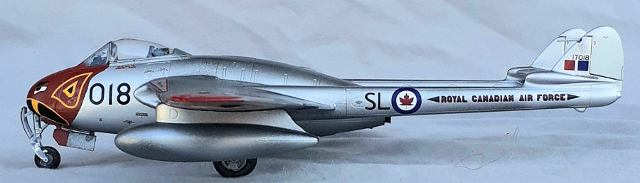
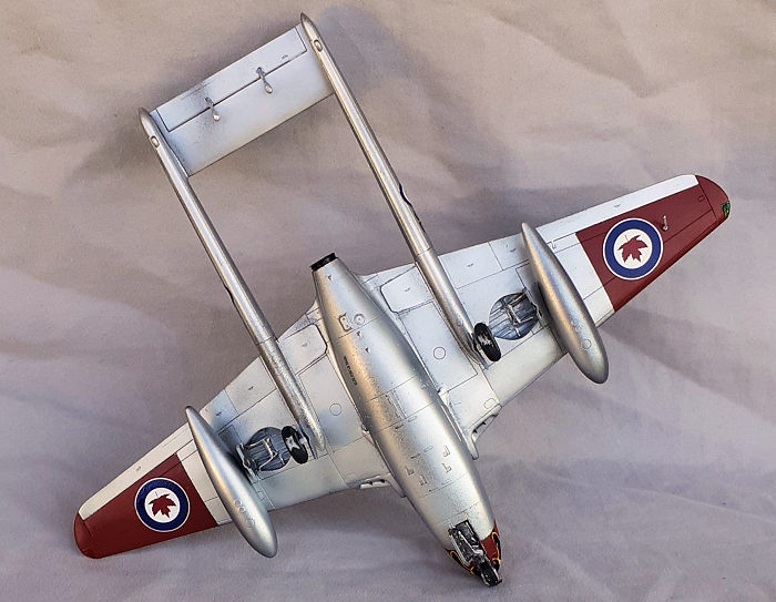
Decals for three options are found in the folds of the instructions. All three options are for aircraft in museum collections. Depicted on cover is the first option, VT812 found at the RAF Museum, Hendon, United Kingdom. Option two is 442 “City of Vancouver” at the Comox Airforce Museum, Comox, British Columbia, Canada and sports a bat head motif on the nose. The third is P42408/AE-B found at the Gardermoen Museum, Oslo, Norway. All have the primary color in High-Speed Silver.
The instructions are in a 16-page booklet. The first two pages cover a brief history in five languages and the usual cautions and symbol explanations. The next 10 pages illustrate assembly sequence starting at the lower wing/fuselage and continues over 87 steps. If the flaps are to modeled up, steps 39 through 52 can be skipped. Most of the steps show only one or two pieces added.
Color call-outs for interior paints just list the Humbrol number, not the name of the color, while the names are given for the exterior colors.
| CONSTRUCTION |
 Deviating
from my usual deviations from the instructions, this build was done by following
them as laid out. When I got to installing the cockpit floor in step 21, I put
ballast underneath it to make sure the model would sit on the nose wheel. I was
premature adding the ballast. In step 33, the instructions call for 17 grams
placed inside the nose cone. The antenna protruding the lower right wing called
for in step 32 was saved for later.
Deviating
from my usual deviations from the instructions, this build was done by following
them as laid out. When I got to installing the cockpit floor in step 21, I put
ballast underneath it to make sure the model would sit on the nose wheel. I was
premature adding the ballast. In step 33, the instructions call for 17 grams
placed inside the nose cone. The antenna protruding the lower right wing called
for in step 32 was saved for later.
I followed the instructions diligently through to step 38, where the flaps are installed, when I then deviated from the instructions. I jumped ahead to steps 76 through 79 to install the wing tips and ailerons, plus the final steps installing the clear parts, to get the model ready for painting.
| COLORS & MARKINGS |
 I felt
compelled to apply the decals for the Canadian plane. After masking the clear
parts, they were sprayed with Alclad clear primer, then the entire model coated
with Alclad’s gray primer. Tru-color Insignia Red was applied to the wings and
nose, then masked for Alclad’s black base, followed by White Aluminum as a
substitute for High-Speed Silver. A clear coat got the model ready for decals.
I felt
compelled to apply the decals for the Canadian plane. After masking the clear
parts, they were sprayed with Alclad clear primer, then the entire model coated
with Alclad’s gray primer. Tru-color Insignia Red was applied to the wings and
nose, then masked for Alclad’s black base, followed by White Aluminum as a
substitute for High-Speed Silver. A clear coat got the model ready for decals.
Several sessions were used to apply all the decals and they behaved nicely. Solvaset was needed to the fang decals to conform to the nose. Another clear coat was applied and the building continued.
Resuming at step 53, the landing gear was installed followed by the drop tanks. Note that they are handed. The Probe from step 32 was added plus the elevator mass balances. The last piece was the pitot on the left fin.
| CONCLUSIONS |
The engineering of this kit is very well thought-out. Most of the parts fell into place. I did have difficulty mating the upper and lower halves together and the intakes, but I eventually got there. My biggest problem was self-induced. I didn’t add enough ballast and ended up packing the nose gear bay with more lead. I’m not sure that 17 grams is enough, so be sure to verify the balance.
Builders should end up with a great model by following the instructions and it should be a straight-forward build out of the box. I spent about 30 hours on this project.
Some unused parts hint at other variants to be released in the coming years.
20 August 2024
Copyright ModelingMadness.com. All rights reserved. No reproduction in part or in whole without express permission.
If you would like your product reviewed fairly and fairly quickly, please contact the editor or see other details in the Note to Contributors.