KoPro 1/72 NC 701 Martinet
| KIT #: | 3135 |
| PRICE: | $34.00 |
| DECALS: | Two options |
| REVIEWER: | Torben Plesberg |
| NOTES: | Conversion of Si-204 kit. |
| HISTORY |
The Siebel 204 was a twin engine aircraft capable of carrying 8 passengers or 1650 kg of cargo. It was designed for the Lufthansa Airline (Si 2o4 A), but the political scene changed radically in 1939 and the Luftwaffe needed a training aircraft for bomber crews. For this purpose the cockpit lay-out was changed to a stepless cockpit, a feature of the German bombers.
 However, the two first
prototypes were with the Lufthansa stepped cockpit, all other aircraft had the
Luftwaffe glazed nose. The third prototype did not fly until the beginning of
1942, and because the Si 204 was a less important war plane, the production was
transferred to France (SNCAN) and the Czech Protectorate (CKD).
However, the two first
prototypes were with the Lufthansa stepped cockpit, all other aircraft had the
Luftwaffe glazed nose. The third prototype did not fly until the beginning of
1942, and because the Si 204 was a less important war plane, the production was
transferred to France (SNCAN) and the Czech Protectorate (CKD).
The Si 204 was mostly used as a training aircraft and as a taxi aircraft for air crews. Some senior officers used the Si 204 as their personal transport aircraft, for example Josef Kammhuber, who built up the German night fighter arm and was its supreme commander. A Si 204 was used as a diplomatic plane for Albert Speer’s peace negotiations in April 1945. The very last German plane downed by an allied fighter was a Si 204 in Bavaria on the 8th of May 1945.
All together 1216 aircraft were produced during the war, but the production continued in France and Czechoslovakia a few years after the war. In France it was known as the NC 701 Martinet. This aircraft differed from the original Si 204 by its French Renault engines and 3-bladed propellers. The Czech aircraft was called C-3A (flying training) or C-3B (crew training). The post war production of the Si 204 continued until 1949, and 240 aircraft were built in France and 179 in Czechoslovakia.
The grand total of the German designed Si 204 amounted to 1216 + 240 + 179 = 1635 aircraft. However, this figure is a minimum figure because the statistics only goes to ultimo January 1945. It is not known how many aircraft were produced from February and to the end of the war – the 8th of May 1945.
The Si 204D was the main variant and produced in by far the greatest numbers. A number of air forces operated the aircraft after the war: The Czechoslovakian AF, the French AF, the Polish AF, the Swiss AF and even the Red AF (captured aircraft). Besides there were some civilian operators, who operated the Si 204 for aerial photography and for mapping photography. The aircraft was very well suited for this purpose thanks to the superlative view from the aircraft and the very suitable size.
 Rikets Almänne Kartverk (the
Swedish Cartographical Department) bought two NC 701 Martinet in 1948 from the
French factory, and a further three aircraft in 1963 from the French AF. One of
the 1948 aircraft was withdrawn from service in 1952 (SE-KAG), and the other
aircraft were operated until 1970, except the subject of my model, the SE-KAN,
which was in service between 1963 and 1967.
Rikets Almänne Kartverk (the
Swedish Cartographical Department) bought two NC 701 Martinet in 1948 from the
French factory, and a further three aircraft in 1963 from the French AF. One of
the 1948 aircraft was withdrawn from service in 1952 (SE-KAG), and the other
aircraft were operated until 1970, except the subject of my model, the SE-KAN,
which was in service between 1963 and 1967.
“Kartverket” operated two other very interesting types of aircraft: the Focke Wulff Fw 58 Weihe from 1938 and to 1957, and the Junkers Ju 86 from 1952 and to 1957.
Two examples of the Martinet survives to this day, one of them can be seen in the Swedish Airline Museum at Arlanda Airport in Stockholm (SE-KAL), and the other (SE-KAE) can be seen in the Swedish AF Museum at Linköping (Malmen).
| THE KIT |
The Czech KOPRO 1/72 Siebel 204 D/E is the only injection kit so far. Recently an injection kit to a 1/48 scale was released by MPM Productions. KOPRO is short for Kovozávody Prostejov. It is a rather old kit from 1976 and is not quite up to modern standards.
There are three sprues. A large one containing all parts except the wings, which are on a smaller sprue. The third sprue contains all the clear parts with several options for different versions: D or E. The plastic is medium gray.
 The only parts that fit well
together are the wings. The engine nacelles are almost as bad as those of the
old FROG Shackleton kit. The two fuselage halves are not entirely symmetrical,
and if put together, the one piece canopy will appear about 1 mm too broad as
seen from the front. The propeller assembly is rather crude. The tail planes
have a dihedral, and are not easy to fix in the correct angle. All the clear
parts and the minor parts are of a good quality. The landing gear is OK, but
difficult to fix correctly.
The only parts that fit well
together are the wings. The engine nacelles are almost as bad as those of the
old FROG Shackleton kit. The two fuselage halves are not entirely symmetrical,
and if put together, the one piece canopy will appear about 1 mm too broad as
seen from the front. The propeller assembly is rather crude. The tail planes
have a dihedral, and are not easy to fix in the correct angle. All the clear
parts and the minor parts are of a good quality. The landing gear is OK, but
difficult to fix correctly.
There are big rivets, and the panel lines are raised and too dominating. It will be necessary to deal with the rivets and the panel lines in the same way as with the FROG Shack. They do not need to be sanded away completely, but they need some dampening.
The instructions consist of four A4 pages with all necessary guidance to complete the model in 8 steps. There are two four-plane drawings showing the color schemes and markings of the two options. The color guide is with a reference to Humbrol numbers.
The decal sheet is with two options for a D (VE + PX) or an E (red D) version of the Si 204. The quality seems OK – but I did not use any of the decals for my model.
The dimensions of the kit are fine, compared to official data of the Si 204 D. The actual scale is actually 1/72. The data from the Wikipedia article are not entirely correct. The length is wrongly quoted as 13.00 m, it should be 11.95 m. (= 39 feet 2.25 inches) Data from: Enemy Aircraft of WW II by Kenneth G Munson, 1960.
| CONSTRUCTION |
Since I wanted to produce an NC 701 Martinet from the kit, it was necessary to line up, what had to be changed.
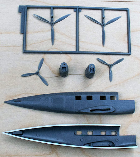
The two- bladed propellers have to be changed to three-bladed ditto and new spinners were needed, too.
The windows are too small compared to the windows on the photos of the Swedish Martinet. They should be one mm higher.
The Martinet has an air-intake on the dorsal of the rear fuselage – and a small rounded pipe behind.
The Martinet has a small beacon on the dorsal
There is a pitot tube in the left outer wing.
There is a white blade-antenna on the belly beneath the wing.
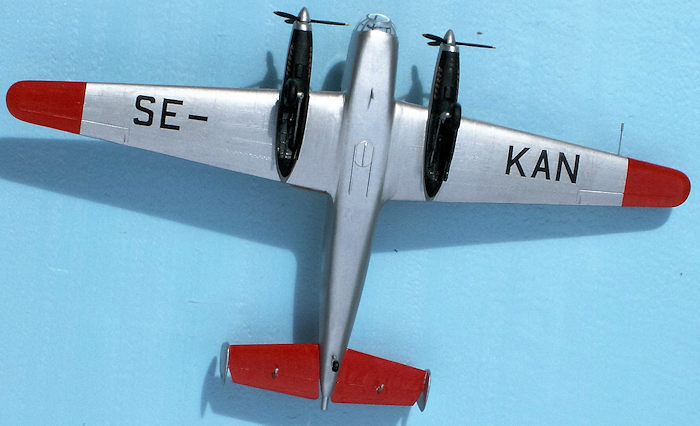
On the belly beneath the wing there is a rearwards sliding door protecting the vertical mounted camera, when this is not in function.
The framing of the frontal glazing is either not identical to that of the Si 204, or the framing is simply wrong, and need to be modified. The problem is that the circular convex front window is too small and placed too far downwards.
There is a rod antenna on the dorsal just behind the front glazing.
A little behind the rod antenna there is a “V-antenna”.
The kit is rather simple to put together, and all parts fit, but there are only a few pins and holes to secure the exact positions. In order to make the front glazing fit properly to the fuselage, I found it convenient to glue a 0.75 x 2.0 plastic strip to one of the fuselage halves. In this simple way the fuselage got 0.75 mm wider, and this helped a lot to make the fit of the nose glazing easier.
The tail planes had the fins glued in place in the correct angle, before the tail planes were glued to the fuselage. I made a jig both for the tail planes and for the wings just to secure the correct dihedral in both places. The two fuselage halves were not symmetrical. The left half needed some sanding of the dorsal about one third from the rear end.
The biggest single operation was to make suitable 3-bladed propellers and new spinners. In my stock I found a sprue with two pointed 3-bladed propellers from the Hasegawa Lancaster kit. The propeller blades needed to be cut shorter about one cm and made somewhat smaller in the middle, and new tips were formed.
The remaining problem was to produce two new spinners
matching the propellers exactly. I figured out that acryl would be the best
material for this job. A four cm long 6 mm gauge rod was convenient for the
purpose, and I turned a spinner in each end of the rod. Now the three holes for
the propeller blades were drilled (1.5 mm drill) 2.5 mm deep by means of the
dividing apparatus of my lathe. Then the two spinners + one cm extra was cut
from the rod. The extra one cm was necessary to fix the spinners properly in the
chuck for the next operation: Drilling of a center hole to give room for the
propeller hub inside the
spinners. This was done with a 4.2 mm drill, and the
hole should be 3 mm deep as measured form the bottom of the spinners. The final
operation was to cut the finished spinners from the one cm extra rod,
 and this
was done with my mini circle- saw. At last the three holes should be opened
towards the bottom of the spinners. The result was very good , indeed: the
spinners simply snapped in place on the propellers – no glue necessary.
and this
was done with my mini circle- saw. At last the three holes should be opened
towards the bottom of the spinners. The result was very good , indeed: the
spinners simply snapped in place on the propellers – no glue necessary.
The nacelles did not fit very well, and the shape was not too good. They needed a lot of sanding and filling before they would do. The exhausts were very crude, but were possible to improve with a new pointed scalpel blade. I put some brass tubes into the nacelles as bearings to make the propellers turn properly. It is a good idea to let one tenth of a mm of the bearing tube protrude from the engine front plate, this will secure a free turning of the propeller.The gauge of the hole in the brass tube should be one tenth of one mm bigger than the propeller shafts. It was not possible to secure the propeller shafts inside the nacelles from falling off, but it is only a question of not letting the model point downwards, when handling it.
The undercarriage was rather simple to make, however it was not easy to fix the legs in the correct position as seen from the front, probably because the wheels are not vertically mounted, but lean a bit outwards.
The window frames were filed half a mm bigger in the top and ditto in the bottom. This operation rendered the windows of the kit unusable. Fortunately, I had eight spare windows from another kit in my stocks, and these fit perfectly in the width, but were one mm too tall. To deal with this problem, my milling machine was perfect. It was a rather simple matter to fix the windows in the vice and mill the surplus mm off. The windows were of the type to be glued from the inner side of the fuselage, just like the windows of the kit. The steps secure that the windows conform with the outer side of the fuselage, but only if the thickness of the sides of the fuselage are equal to the thickness of the windows. This was not the case, and I had to sand the inner side of the fuselage halves until the correct thickness was obtained in the window areas.
The main issues of making the conversion were finished, and now it was time for the details:
The air intake on the dorsal was made of a plastic strip 4 x 3 mm. The opening was milled, and the outer shape was formed by filing and sanding. Behind the air intake there is a small bent tube. This was made of a small piece of 2 mm brass rod. The brass had previously been heated up to almost white-hot temperature to eliminate the hardening. Otherwise it would not be possible to bend the rod 90 degrees so narrowly.
 The small beacon was a 2.2 mm gauge 3,5 mm small piece of
acryl, rounded in the top. The blade antenna placed on the belly under the front
of the wings was just a small piece of thin white plastic-card. No need for
painting!
The small beacon was a 2.2 mm gauge 3,5 mm small piece of
acryl, rounded in the top. The blade antenna placed on the belly under the front
of the wings was just a small piece of thin white plastic-card. No need for
painting!
On the belly in the middle of the wings there is a rearwards sliding door to protect the vertical camera, when it isn’t taking pictures. The door was made of 0.3 mm plastic-card and the sliding frame was made of very thin plastic strips. This – and all other details I constructed according to documentation in Björn Karlström’s book “Flygplansritningar 7 –Planes and Helicopters in Public Service”. This publication contains a scale drawing 1/72 of the Martinet and 11 photos of the real aircraft.
The framing of the frontal glazing is not identical to the Si 204 and needed a correction. However, I chose not to take the trouble and make this correction. There were two good reasons for that decision:
I had bought a new re-tooled kit of the Martinet – without the shortcomings of the original old kit.
My son Nicolai had a vacuum-formed canopy from Falcon Models for the Martinet in his stocks. This canopy had the correct framing, and Nicolai was willing to let me buy it!
Finally, there are two small antennas on the dorsal behind the canopy. A pointed rod antenna and a V-antenna. The last mentioned was cut of 0.5 mm plastic-card, and the two small arms and holder were 0.5 mm brass rod.
| COLORS & MARKINGS |
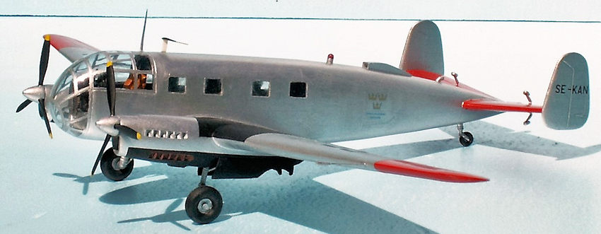
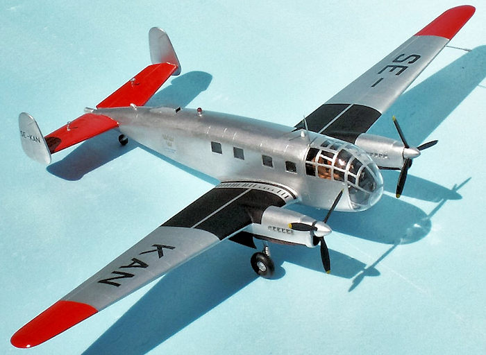
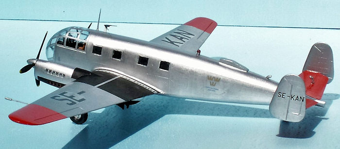
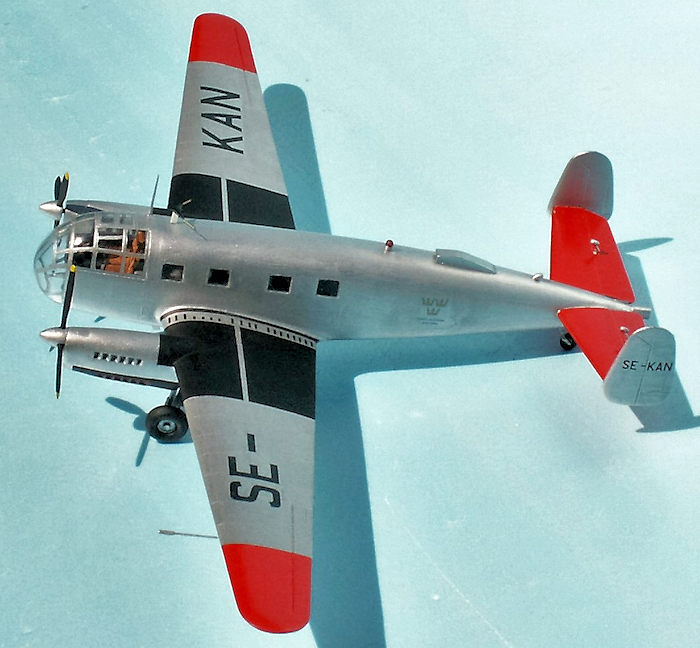
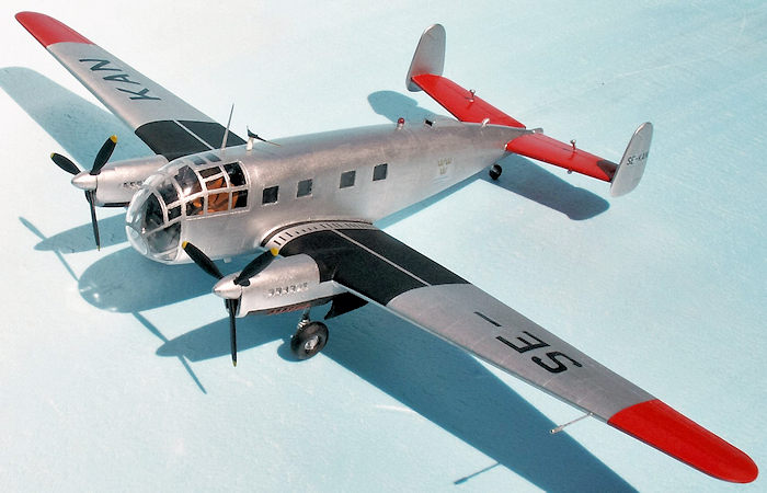
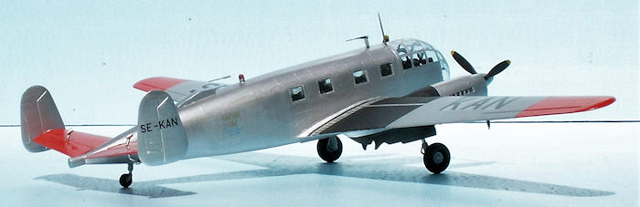
The Swedish Martinets had during their service life at least four different color schemes according to the photos in “Flygplansritningar 7”. I chose the most colorful among these, and my model should be the SE-KAN.
The basic all over color is aluminum (HB 2702). From this color there are the following exceptions:
The tail planes and the outer wings are bright red (Revell no 31). The underside of the nacelles are black (Model Master flat black). The upper sides of the inner wings are black with the exception of the walk-ways close to the fuselage. They are black stripes in a certain pattern, and this feature was suitable as decals. I drew the black pattern on a sheet of clear decal paper. The propeller blades are black with yellow tips (HB 69).
 As to the interior I had no documentation at all. The
instructions suggests dark sea gray (HB 164) for interior of the cockpit, and
dark earth (HB 29) for the pilot seats. This was my choice. The wheel wells got
dark sea gray as well. The top of the beacon got a touch of transparent red (HB
1321). This paint is very special. You must be very fast with the small brush,
or the whole thing changes into some dark stuff! I had to try about 8 times
before the result was OK. By far the most difficult paint-job! It was easier to
paint the frames of the canopy.
As to the interior I had no documentation at all. The
instructions suggests dark sea gray (HB 164) for interior of the cockpit, and
dark earth (HB 29) for the pilot seats. This was my choice. The wheel wells got
dark sea gray as well. The top of the beacon got a touch of transparent red (HB
1321). This paint is very special. You must be very fast with the small brush,
or the whole thing changes into some dark stuff! I had to try about 8 times
before the result was OK. By far the most difficult paint-job! It was easier to
paint the frames of the canopy.
The marking decal sheet was bought separately. The Hobby Center in Helsingborg offered a special sheet containing all the letters for the five Swedish Martinets + two badges of “Kartverket” appearing on each side of the fuselage. The decals are correct, but the carrier film is too thin, and great care must be taken when applying them.
| CONCLUSIONS |
It was exciting to build this very special and odd-looking aircraft. Even if the kit was not up to modern standards, it was possible to get a reasonable model in the end. I shall recommend the kit to everyone, who wants to build a model of an aircraft most people do not know even existed. However, the new tool kit (# KPM 0054) appeared in 2005 and this is the kit, which is on stock in the shops right now. Don’t hesitate to buy it – either as the Siebel Si 204 D/E or as the NC 701 Martinet.
Last night I watched a movie on TV, “Triple Cross” with Christopher Plummer as the spy. During his training as a German soldier he learned to jump with the parachute from an aircraft painted in Luftwaffe colors – a Martinet!
| REFERENCES |
Wikipedia: Siebel Si 204
Björn Karlström: Flygplansritningar 7, Allt om Hobby, Box 90 133, 120 21 Stockholm. ISBN 91-85496-68-5
30 August 2016
Copyright ModelingMadness.com
If you would like your product reviewed fairly and fairly quickly, please contact the editor or see other details in the Note to Contributors.