| KIT #: | n/a |
| PRICE: | |
| DECALS: | None supplied |
| REVIEWER: | Pablo Calcaterra |
| NOTES: | 3D printed. Hasegawa 36197 and Condor decals. |
| HISTORY |
The Pulqui I was the first jet plane designed and flown in Latin America putting Argentina in the small group of 9 countries that had (had) such technology (Germany, Britain, Italy, USA, Japan, USRR, Sweden and France).
Design of the plane started in 1946 and the initial team was made up of Argentine engineers from the Instituto Aerotécnico from the Ministry of Aeronautics. Led by Juan Ignacio de San Martin the I.Ae. had developed several planes in the previous years, including a trainer called DL.22 (quite similar to the Harvard) of which 200 units were manufactured with local resources and sporting a locally designed engine (El Gaucho).
While Engineers Cardelillach, Ricciardo and Morcchio were working on the jet plane, the (in?)famous Emile Dewoitine arrived in Argentina escaping from France as he had been a Nazi collaborator during the German occupation of France. The Frenchman had with him a design of a jet plane. He signed a contract with the Argentine government and joined the team of Argentine designers who were not happy of having this “intruder” in their team.
A wooden mock up was put together for the wind tunnel. The plane was ready to fly in fourteen months. It was a very simple design with straight wings that were an entirely new development in the world (result of the Argentine engineers and called IAe242-1 and was a laminar flow type with low drag. It was not, as some sources say, copied from the P-51s because the Argentines had never seen on up close). The speed the plane could achieve was limited because the wings were straight and not arrow shaped (like the later Pulqui II designed by Kurt Tank).
The plane was built using parts taken from others already in service in the Argentine Air Force. For instance, it is said that the nose wheel was taken from a Ju52, the wooden seat was from a DL22 and the Rolls Royce Derwent came from a Meteor. Compressed air was used to retract the landing gear and this dropped by gravity. The air intake was channel thru two ducts beside the pilot between the cockpit and plane walls. Engine was placed just behind the pilot and a long (almost 5 mts) pipe took the gases to the exhaust under the tail. Control surfaces were moved using push-pulls, no cables were used. Flaperons were installed on the wings. The radio installed on the plane could only transmit but not receive. The plane did not have an ejection seat. Had the pilot been forced to bail out the procedure called for him to invert the plane and let the gravity do the rest…Being such a small plane range was only 800/900 km. Ceiling was 15,000 meters and endurance in the order of 90 minutes.
 First flight took place on
August 9, 1947 around 4 pm. The plane was taken from the factory to the airfield
loaded on a truck due to the fact that the runway of the factory was too short
for this plane to use and thus it had to be flown from the one used by the
Parachutists which was longer. Pilot was Edmundo “Pincho” (read below) who
commented “This is the plane in which I am going to get killed” before boarding
it. He flew wearing his service cap, a leather jacket and his gaucho pants!
Shortly after taking off Weiss started to roll to the left to the consternation
of the engineers who had told him to go easy on the plane. Assuming that he was
following their order they thought the pilot was in trouble. But to their relief
the plane had a flawless 28 minute long first flight. Weiss even did some stunts
during the flight. Upon landing the engineers asked him why he had rolled and
Weiss answered that the controls felt so good that he felt boldened enough to do
such a maneuver. Weiss was the only pilot that flew the plane during all the
test flights.
First flight took place on
August 9, 1947 around 4 pm. The plane was taken from the factory to the airfield
loaded on a truck due to the fact that the runway of the factory was too short
for this plane to use and thus it had to be flown from the one used by the
Parachutists which was longer. Pilot was Edmundo “Pincho” (read below) who
commented “This is the plane in which I am going to get killed” before boarding
it. He flew wearing his service cap, a leather jacket and his gaucho pants!
Shortly after taking off Weiss started to roll to the left to the consternation
of the engineers who had told him to go easy on the plane. Assuming that he was
following their order they thought the pilot was in trouble. But to their relief
the plane had a flawless 28 minute long first flight. Weiss even did some stunts
during the flight. Upon landing the engineers asked him why he had rolled and
Weiss answered that the controls felt so good that he felt boldened enough to do
such a maneuver. Weiss was the only pilot that flew the plane during all the
test flights.
Though the projected speed was in the 850 km/hr the plane only was able to achieving 720. By removing the rounded wing tips and replacing them with shorter square ones the speed was increased to 750 km/hr. Still quite short from what it was designed to do. A few days later the plane was flown from Cordoba to Buenos Aires to be shown to Presidente Peron. Then it was exhibited at the Aeronautics Show downtown Buenos Aires during September 1947. After an accident between a taxi and the truck that was transporting it back to the Buenos Aires airport repairs had to be made to the plane. Finally, the plane was able to return to Cordoba to continue with the test flights. The Pulqui I was presented again in flight to the Buenos Aires public early December and again on October 8, 1948 at the Buenos Aires airport.
Dewoitine asked for a 5 million pesos contract to build the successor of the Pulqui, a plane with 4 x 20 mm guns and more capable. He even had designed a two seater trainer version. But between the disappointment of the results of the Pulqui I and now the presence of Kurt Tank already starting to work on the much advanced Pulqui II (derived from the Ta183) his proposal came to nothing and the Frenchman left the country.
The Pulqui I project was cancelled; the plane was initially stored in a hangar in Cordoba and then moved to the Museo Aeronáutico in Buenos Aires by the River Plate in the 60s. Exposed to the elements for many years (I visited the place several times as a kid) it was finally restored starting 1996 and then moved to the much better new Air Force Museum located at the Base Aérea Moron in the Greater Buenos Aires. On the side of the Pulqui I you can see a Rolls Royce Derwent V used by the prototype, which had been returned to a Gloster Meteor after the project was cancelled and that flew for the last time in Meteor C-051 on December 29 1970.
Edmundo “Pincho” Weiss was an officer of the Argentine Army since 1941 he got the transfer to the Air Arm (there was no independent Air Force yet) the following year. Being such a talented pilot, he was transferred as test pilot to the Fabrica Militar de Aviones in 1946. His first flight was in the I.Ae-24 Calquin, a local design very similar to the DeHavilland Mosquito but that sported radial engines. In 1947 he was became one of the team members responsible for the introduction of the Meteors to the Argentine Air Force (100 were purchased). As an example of his prowess, he flew 4 different DeHavilland models at the factory on the same day…and with no dual command time! He became the first Argentine to break the sound barrier flying a De Havilland DH-108. The Queen gave him a ring that only the first 15 pilots that broke the sound barrier have. He witnessed the death of Geoffrey De Havilland. Back in Argentina he executed the first flight of the I.Ae.33 Nancu, a design similar to the Hornet. In it he established the unbroken record for a piston engine covering the distance between Cordoba and Buenos Aires in 55 minutes at an average speed of 650 km/hr. Being the most important test pilot in the Air Force he flew the Pulqui II for the first time, pulling rank on the German team who wanted Otto Behrens to be the first. In 1951 he became the Air Attache at the Argentine Embassy in the US. Back in Argentina in 1954 he worked in the Air Ministry. During the 1955 Revolucion Libertadora that overthrew Peron and flying a Beechraft B-18 he was caught by a Gloster Meteor of the rebel side. Flying ultra low and dodging trees he managed to avoid being shot down. When the Peron government fell and as he was loyal to the deposed President he was retired from the Air Force. In 1973 he was restored as a member of the Force. He passed away aged 72 in Cordoba on July 19 1991. The list of planes he flew is very extensive (49 different types) and includes for instance Hawk 75, Glen Martin 139, Ju 52, Meteors III and IV, Chipmunk, Hornet, Vampire, Spitfire Mk 24, Firefly MkIV, Saab Safir, Avro Lancastrian, Fiat G-55, B-25 and Sikorsky S-51. He also was executed the first flight of the following Argentine planes: I.Ae. 24 Calquin, I.Ae. 27 Pulqui I, I.Ae 30 Nancu, I.Ae 31 Colibri, I.Ae 32 Chingolo, I.Ae. 33 Pulqui II, I.Ae. 34 Horten’s Flying wing.
| THE KIT |
 Being a 3D printed model and
downloaded,
it is just a set of parts with very minimal but wide panel lines. No landing
gear is provided, no lines for the landing gear doors. The canopy is part of the
printed frame. A stand is also provided (I chose not to get it printed).
Being a 3D printed model and
downloaded,
it is just a set of parts with very minimal but wide panel lines. No landing
gear is provided, no lines for the landing gear doors. The canopy is part of the
printed frame. A stand is also provided (I chose not to get it printed).
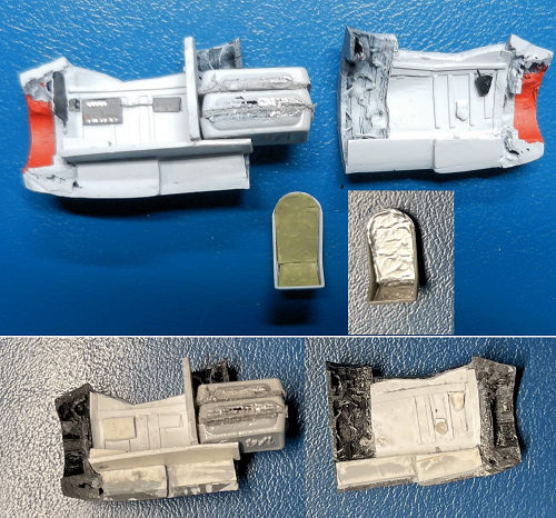
There are 8 parts: wings (x2), nose that ends just before the end of the canopy (?!), front middle fuselage with the front half of the wings roots…and the back portion of the canopy (!), back middle fuselage with the back half of the wing roots, fuselage after the wings, fuselage with front of the tail and the back end of the tail with the last section of the fuselage with the exhaust pipe.
There are three basic mistakes in the model: the air intake is represented as a narrow divider when in fact it was a very chubby one that took most of the intake (it’s like if the 3D model artist had designed a negative of the original intake), the windshield is missing the frames with the top of the hood is too narrow and rounded and finally the undersides of the wings are missing the curves associated with the border of attack of the flaps.
Having purchased the model for less than CAD 5, I passed the files to a fellow member of the local IPMS who printed the parts in black material.
| CONSTRUCTION |
I had never built a 3D printed model and probably have never used 3D parts. Having seen models 3D printed I was not surprised that the surfaces were “corrugated”. (This is a problem with 'string' printers. A resin printer will not exhibit this feature, but it more expensive and has a somewhat sharper learning curve. Ed)
While I was finishing my excellent Accurate Miniatures Dauntless I started to sand one of the wings first with coarse and then with fine wet sandpaper. In doing so most of the panel lines were erased but there were some shallow areas that still showed some corrugation. I used some Tamiya putty and covered those imperfections. Using as a reference the unbuilt CMK 1/72 resin model of the Pulqui I that I purchased while on vacation and visiting Hannants in Lowestoft in 2000 I scribed the panel lines and ailerons. Confident that it was not going to be such a hard task to eliminate the uneven surfaces I tackled the rest of the model once the Dauntless was complete (side note: what a great kit! It took me only 17 short days to finish it)
Having now the confidence that sanding of the 3D model was not going to be that hard and after having enjoyed myself with a complex but easy to build model (Dauntless) I dove head first into the darkness of a 3D model…
Wings: With one wing ready the next step was to try to see how well would my favourite two-part epoxy (JB Weld) would fare to get the parts glued. For this I used the two middle parts of the fuselage (those with the wing roots). With careful alignment and using some painter tape to make sure things would not shift out of place I let the parts dry overnight. The epoxy had really become part of the 3D printed parts. There was some excess of glue sticking out of the union. It was not bad…sanding it out along with the rest of the surface area gave me a continuous surface with no indication that these had been 2 parts before.
I sanded and scribed the right wing like I had done with the left one.
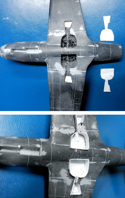 Wheel wells part I: The next step was to start to
create the wheel wells in the lower fuselage area. Using the CMK kit as a
reference and expanding the openings by 50% I drew the openings on the lower
surfaces. Then with a small drill bit from my hobby drill I made holes along the
internal edge of the lines. These were then expanded with a larger drill bit.
Finally an Xcto knife finished the rim of the openings. More drilling in the
openings area removed more material. Once the basic openings were ready, I left
the parts aside. Depth and more accurate demarcation lines were going to be made
once the wings were attached.
Wheel wells part I: The next step was to start to
create the wheel wells in the lower fuselage area. Using the CMK kit as a
reference and expanding the openings by 50% I drew the openings on the lower
surfaces. Then with a small drill bit from my hobby drill I made holes along the
internal edge of the lines. These were then expanded with a larger drill bit.
Finally an Xcto knife finished the rim of the openings. More drilling in the
openings area removed more material. Once the basic openings were ready, I left
the parts aside. Depth and more accurate demarcation lines were going to be made
once the wings were attached.
Canopy part I: Next challenge was the canopy/nose. First, I had to create a new master of the canopy as I wanted to build a full cockpit with a clear canopy and windshield. As I mentioned previously the front of the fuselage has most of the canopy but the next section has the end of the back portion of the canopy. Out came the painter’s tape. I presented the nose to the already glued 2 sections of the middle fuselage. Then I built a structure with blue tac and cardboard up from the fuselage under the canopy up past the canopy. It was kind of a bath tub with the canopy at the bottom of it. I poured plaster of Paris and let it dry overnight. Removed the cardboard walls and the blue tac and the negative of the canopy was clearly imprinted in the plaster. Using JB Weld I filled the plaster using a toothpick. Another wait overnight and the plaster was chipped away with an X-cto knife. The final layers of plaster were removed with a toothbrush under running water. A very nice master of the windshield/canopy was created that also included a bit of the fuselage. I had to improve the frames a bit (under represented). Then I passed this master to my friend Anthony Goodman who has a lot of experience and tools to make clear parts. He further cleaned the master and created a base with holes to ensure the vacuum would pull the clear plastic to the bottom sides of the canopy. It was a week later that it dawned on me that the 3D representation of the canopy had the flaws I mentioned above: rounded windshield with no frames, top portion of the hood too narrow and rounded instead of being somehow flat and wider. I decided to create a new master, this time for the windshield and with the correct frames. But this came later on.
 Cockpit: In order to create the cockpit I decided that
the easiest solution was to cut the front fuselage part in 3: the front ring
with the air intake was cut first and once this one was removed I cut the
remainder part vertically. These were accomplished using the hobby drill and a
round saw. And here for the modeller a SAFETY NOTICE: I had had these tiny round
saws crack in the past. For some reason this day I decided not only to wear my
safety glasses but also a face shield from the Covid times. When I was about to
finish cutting the canopy area in two the darn wheel cracked and snapped…and
flew to my face hitting me in the forehead area….where the shield was protecting
me. Hard to believe but only time I use the shield and saved the day. Listen to
that inner voice!
Cockpit: In order to create the cockpit I decided that
the easiest solution was to cut the front fuselage part in 3: the front ring
with the air intake was cut first and once this one was removed I cut the
remainder part vertically. These were accomplished using the hobby drill and a
round saw. And here for the modeller a SAFETY NOTICE: I had had these tiny round
saws crack in the past. For some reason this day I decided not only to wear my
safety glasses but also a face shield from the Covid times. When I was about to
finish cutting the canopy area in two the darn wheel cracked and snapped…and
flew to my face hitting me in the forehead area….where the shield was protecting
me. Hard to believe but only time I use the shield and saved the day. Listen to
that inner voice!
With the nose cut in 3 parts I started to carve out the internal beehive structure. Once I had almost got to the internal side of the thick surfaces I began to create the walls and floor using small pieces of Evergreen. Using excellent pictures of the cockpit I found on line (plus a great 3D You Tube video that allows you to do a 360 in the cockpit) I scratchbuilt the boxes and cockpit frames plus the nose landing gear well.
I painted the cockpit using Vallejo Light grey primer (a very good match of the Pulqui’s cockpit colour in my opinion) and with black I painted some of the boxes. The buttons on the right handside box were carefully painted. A piece of wire represented some of those connecting the front and back box on the right handside. The throttle quadrant was made with a piece of Evergreen and painted black along with the throttle itself. The seat came from the spares (a US P-40 seat from the Airfix kit). I had to extend the rounded backrest and make it taller. The pad of the seat was made using foil from a bottle of wine. Seat belts came from even thinner aluminum foil. I also scratch built the stick and the rudder pedals plus the prominent top of the front landing gear wells that sticks into the cockpit.
It was at this point clear that the kit was going to be a tail sitter. In order to make the tail lighter I drilled all the fuselage sections including the middle ones. I used our digital kitchen scale and took the weight of the nose sections and the one of the fuselage and tail. The middle fuselage/wing roots was estimated to be distributed evenly in terms of weight (front and back). These readings gave me a deficit of 21 grams of weight for the front portion. The lead self adhering segments are too long to sit behind the fuselage wall so I had to carve out a significant hole in the front of the fuselage part that has the border of attack of the wings. After some frustrating work I was able to open a gap large enough for the protruding 3 x 7 grams autoadhesive segments to fit inside the following segment of the fuselage.
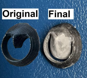 Air intake: To fix the rachitic air intake I made two
lobes with blue tac and put them on the sides of the intake split. Again with
plaster of Paris I filled the internal air intake. Once ready I bent out the
blue tac and was left with the holes that were filled with JB Weld. Once these
were removed I had a decent but not good enough pair of round lobes to be glued
to the center of the air take. It took me several sessions of sanding,
presenting, sanding again till the intake resembled the Pulqui’s. Some Tamiya
putty was required to deliver a smooth surface. As you can image working in such
a “confined” area was very tricky.
Air intake: To fix the rachitic air intake I made two
lobes with blue tac and put them on the sides of the intake split. Again with
plaster of Paris I filled the internal air intake. Once ready I bent out the
blue tac and was left with the holes that were filled with JB Weld. Once these
were removed I had a decent but not good enough pair of round lobes to be glued
to the center of the air take. It took me several sessions of sanding,
presenting, sanding again till the intake resembled the Pulqui’s. Some Tamiya
putty was required to deliver a smooth surface. As you can image working in such
a “confined” area was very tricky.
Front fuselage: Now it was time to put the nose back together. When I cut the original part with the small rotary saw I lost almost 1 mm in fuselage width and another one between the intake and the cockpit area. There was then a gap to be filled but at the same time I had to ensure that everything was aligned again. After putting JB Weld on the front of the fuselage portion I presented the side of the cockpit that had the weights and ensured a smooth fuselage wall. Then the other half was also presented and again the fuselage surface continuity was achieved. But this left a gap between right and left halves which was painfully evident. To ensure that these halves were sitting as parallel as possible I then applied JB Weld to the intake ring (to which I had added a single SS ball…just in case my calculations had been on the edge) and presented it to the cockpit portions. I allowed the excess of glue to ooze out as it would help me cover the gaps. With painter’s tape and while the parts were sifting position I secured them in place. Another overnight cure session. The following day the tape was easily removed and the 3 parts were properly aligned (phew!). The gap on the spine of the front fuselage (and around the wheel wells) was filled with portions of Evergeen and more JB Weld. The fuselage portion beneath the back canopy was made with a thicker and bent piece of Evergreen. Putty helped to fill some gaps. After sanding the cured glue and putty during several session the nose to fuselage area was finished.
With care I removed the wingtips lights and that one behind the top of the fin. Then little oversized pieces of clear plastic were glued with cyano and once dry sanded smooth with the rest of the surfaces.
Wings and wheel wells part II:The next big challenge was to make the box for the main landing gear. As mentioned above the fuselage area had been already carved out…and I had done the same with the wings but when I presented fuselage to wings I realized they did not properly match. There was a “continuity” problem. Reviewing the CMK model I realized I had drilled the openings in the wings too far back. It took thus some extra work to move these a couple of mm forward. I drilled matching holes on the wings and the roots of the wings on the fuselage, glued some nails cut in half into those holes using JB Weld and with more JB and tape to secure them in place (using some Lego as a jig) the wings were attached to the fuselage.
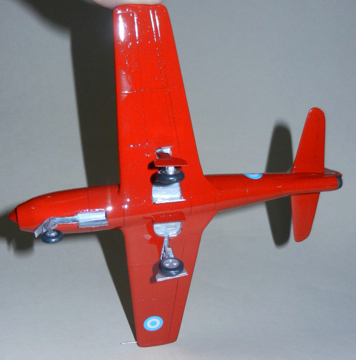
With the wheels that I was going to use I measured the depth required for the landing gear wells (not to make them too shallow). More drilling was needed. I then scanned the landing gear doors and printed them 50% larger on a piece of paper. These I then used as templates to make 3 sets with Evergreen: the roof of the wells and the landing gear doors for which I used 2 sets: the original sized one and another one trimmed slightly smaller to make the thicker internal portion of the doors. With the roofs now in place I made the walls by putting Evergreen pieces cut to the proper length. The excess of the walls was trimmed with an Xcto knife and some putty was required to achieve a smooth edge. Very thin strips were cut to represent the ribs present of the top of the wells. These, once in place, were attached using Tamiya liquid glue. I drilled very shallow holes onto which the landing gear legs were going to be attached.
Fuselage: Much easier was to glue together the main fuselage portion (behind the wings) that I had previously sanded smooth to the tail section (with the excess of JB Weld carefully sanded not to snap in half either the horizontal or vertical surfaces). Then it was a matter rescribing the panel lines, moveable surfaces and scratchbuilding the trim tab of the rudder (thin Evergreen).
With the plane put together it was time to do the final smooth sanding and rescribing of panel lines.
Canopy part II: At this point I went back to the
canopy/windshield portion. After looking at pictures of the Pulqui it dawned on
me that the master I had created had two main problems: the wrong curved
winshield and to the narrow top of the canopy. For the later I decided I was
going to use the two sides from clear part that Anthony was going to make but
the windshield had no fix. I purchased a 5-minute dry plumber putty. It is very
good to make basic structures…but it dries too fast. Nevertheless, I managed to
make a master to which I attached the frames with Evergreen strips. This new
master I took to Anthony’s and an afternoon (afte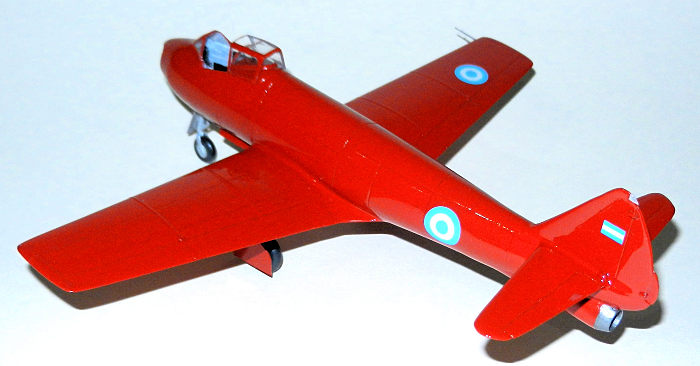 r he had also added holes to
the base of this master) we made 3 sets of windshields and hood/canopies.
Cutting out the best of each one of the 3 I ended up with a good windshield
(front) and two very good hood sides (plus the canopy behind the hood). From the
excess of plastic from his work I made the top rectangular and almost flat top
for the hood and the two sides of the windshield. Trimming and testing here and
there delivered respectable parts. While doing all this work, I realized that
the edge of the cockpit was too shallow and at the wrong angle. With care and
Evergreen, I extended up it up. Using JB Weld the windshield was put in place
after some adjustments to the fuselage. With more Tamiya putty all the fuselage
surfaces around the cockpit were finalized. There are two windows on a single
panel behind the pilot that is attached to the back canopy. I cut this one from
some Squadron acetate and I created two masks for the windows. Then it was glued
to the canopy.
r he had also added holes to
the base of this master) we made 3 sets of windshields and hood/canopies.
Cutting out the best of each one of the 3 I ended up with a good windshield
(front) and two very good hood sides (plus the canopy behind the hood). From the
excess of plastic from his work I made the top rectangular and almost flat top
for the hood and the two sides of the windshield. Trimming and testing here and
there delivered respectable parts. While doing all this work, I realized that
the edge of the cockpit was too shallow and at the wrong angle. With care and
Evergreen, I extended up it up. Using JB Weld the windshield was put in place
after some adjustments to the fuselage. With more Tamiya putty all the fuselage
surfaces around the cockpit were finalized. There are two windows on a single
panel behind the pilot that is attached to the back canopy. I cut this one from
some Squadron acetate and I created two masks for the windows. Then it was glued
to the canopy.
Wings part II: At this point I realized that the lower border of attack of the flaps was not rounded as it should have been. Major surgery (cutting them out and shaping them plus attaching them again) would have been required. I decided to let this “opportunity” go. Upon more detail inspection of the plane sitting at the Air Force Museum I realized that some strips that covered the union of segments of the wings were missing. I found some Tamiya self adhesive foil from my F1 Ferrari and cut strips that I very easily attached to the proper places on the wings. Rivets were added here and there with a riveter wheel.
Landing gear: By a great struck of luck I found that the nose and main landing gear that I had not used in my 1/50 Academy MV Dagger conversion (in flight and as found elsewhere in MM) had practically the correct length and shape. The wheels themselves were from the same kit, having a very similar thickness and diameter. The wheel hubs came from some 1/72 Me109 wheels to which I cut out the wheels themselves. As the 109 had 6 “triangles” and I needed 3 I resorted to covering the 3 I did not need with triangles of Evergreen and some Tamiya putty. I ended up with the hubs that perfectly fit inside the openings of the Mirage wheels! Some putty required to merge the hubs to the wheels and these were ready. The legs had some supports in a different position that those seen in the Pulqui. I cut them and glued them where they belonged. For the nose landing gear there were some challenges: the leg sticks forward a bit (I put some plastic on the back end of the top part that is glued inside the well) but the wheel itself is of the yoke type with a flat hub with 4 holes. For this I found what I think was the wheel of a 1/72 F-4 from when I was a kid and attached it to the nose leg of the Academy kit. The hubs were made with small Evergreen circles I cut and with a pin I made 3 of the holes (the 4th “being” under the yoke). Some actuators were added from the spares and with careful measurements and dry fitting and using another Lego jig the 3 legs were attached.
Finally, and after 45 days of around 4 hours each, the plane was ready for painting!
| COLORS & MARKINGS |
After masking the clear parts and filling the cockpit with foam and wet tissue paper I primed the model with Vallejo Light Grey Primer. Some double panel lines or others that were curved instead of straight showed up. A couple of frustrating sessions to putty, sand, paint, rescribe, putty, sand, paint delivered a better result.
I then painted the wheel wells and legs with Vallejo aluminum. As it had sprayed over the adjacent surfaces with this colour and having a considerable amount of paint in the cup I decided to spray the entire model aluminum. I should have known better….
 After masking the wheel wells and the legs themselves
I started to spray the model with thin layers of the closest red I have in my
inventory (Vallejo 71.003 / RLM23). And what I got was a beautiful shiny gloss
sparkling light red aluminum surface. Four coats later I was still getting a
nice “Pulqui shaped Christmas tree ornament”. I believe it took 7 coats to
finally get rid of the aluminum shade…
After masking the wheel wells and the legs themselves
I started to spray the model with thin layers of the closest red I have in my
inventory (Vallejo 71.003 / RLM23). And what I got was a beautiful shiny gloss
sparkling light red aluminum surface. Four coats later I was still getting a
nice “Pulqui shaped Christmas tree ornament”. I believe it took 7 coats to
finally get rid of the aluminum shade…
The navigation lights were unmasked and those on the wings were painted with clear Model Master Acryl red and green.
Then I used my dwindling stock of Future (probably ½ a bottle left) and applied several thin coats until I achieved a good layer to which I sprayed more Future from a closer distance and in a more aggressive way to deliver a very glossy surface. Luckily the couple of places along the fuselage where it run a bit had disappeared as Future cured (and honestly could not have cared too much about them because you can see in the images that all the panels in the actual Pulqui are somehow curved/uneven). The back canopy and hood had been dipped in Future before painting. Now I realized I had forgotten to paint the exhaust…(eyes rolling). I gently sanded the futured surface, masked the area and airbrushed some black mixed with aluminum. No accidents here.
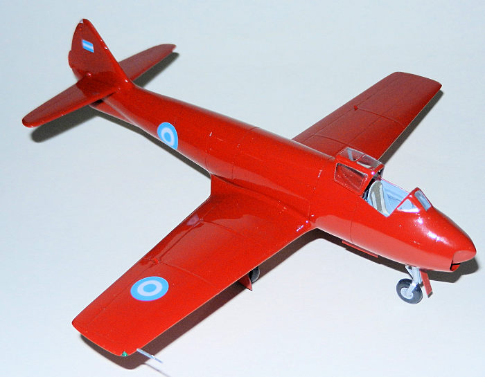
I left the model aside for a week for Future to cure properly. For decals I used four Argentine Air Force roundels from the spares (Condor Decals) and the flags came from a set of Aerocalcas that I had to trim a bit to make them shorter (less than 1 mm on front and back). The structure behind the pilot seat was represented with a decal I made using images from the net (a couple of lids, some stamped ribs to strengthen the panel).
With the decals in place and after cleaning some excess of glue several thin and then thick layers of Future were applied (the first light ones to seal the decals had delivered a semi gloss surface thus ruining my original coat…)
| FINAL CONSTRUCTION |
The previously painted wheels (Vallejo dark grey primer) were drybrushed with Model Master Matte clear varnish. Masks for the windshield, canopy and hood were removed.
Landing gear doors were attached but first I added some wiring to the main legs. Some arms for the doors were added, the most significant ones on the nose.
I realized I was not happy with the instrument panel I
had made using a decal I had designed using an picture of the actual one (image
was not sharp enough and with all the work around the windshield area it had
ended up too deep into the nose). As a consequence, I took a piece of Evergreen,
trimmed it to shape, stuck it tweezers using blue tac and after multiple tries
had something that was better (not perfect though). I made some indents wi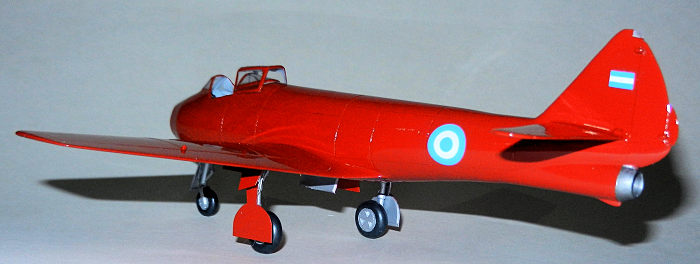 th a
pin to represent the face of the dials, painted the surface in dark grey (and
dials in black) and a couple of sand and red buttons were added per references.
Then again with the tweezers, blue tac and glue I managed to make my way to the
area under the windshield and glue it in place.
th a
pin to represent the face of the dials, painted the surface in dark grey (and
dials in black) and a couple of sand and red buttons were added per references.
Then again with the tweezers, blue tac and glue I managed to make my way to the
area under the windshield and glue it in place.
I realized that the top of the landing gear well in the cockpit was too shallow as it should almost touch the bottom of the instrument panel. Using thicker Evergreen I enlarged it and glued it and then painted it in grey. The seat was attached and the scratchbuilt stick was added.
The back portion of the canopy was glued with white glue and the open hood on top of it.
The final detail came again from an Airfix P-40: the US style pitot tube that I had painted in aluminum.
With this the 2 months long project was finished. I seldom put so many hours in a day on a model but this build happened during my 2-week long break at Christmas time and also I dedicated long hours during the weekends. I am sure that there were days when I worked 8 hours non-stop. Even though the build lasted 2 months it is probably equivalent to 4 o 5 months on a normal working period of time…
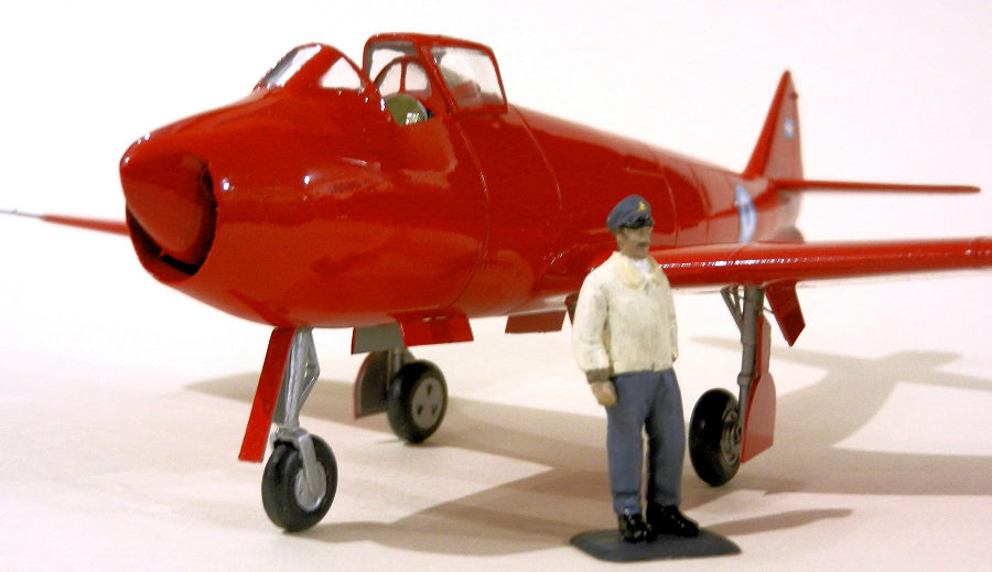
…but I was not done yet! I decided to build a figure of “Pincho” Weiss. I have a set of 1/48 WWII pilots from Hasegawa. I took the legs of the USN pilot and the torso and head of a late war German pilot. The face was modified by sanding the pointy nose and adding some putty to make the face chubbier (like Weiss’). The head I had cut from the torso to present it in a different posture. Several modifications were made to the torso to better represent Weiss’ jacket (it had elastic ends at the end of the arms and bottom of the jacket). I erased some German details from the jacket as well. Finally the head was glued back in place, gaps covered with Tamiya putty (also used to represent his white turtle neck) and then the figure was painted with different colours and brushes including his moustache. With Vallejo Gold the Argentine Air Force wings and badge on the front of the cap were added. A small base to keep it steady was made with Evergreen and painted dark grey to represent the tarmac.
| CONCLUSIONS |
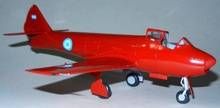
I am proud with the end result. I really looks like a Pulqui I and I am sure that it is a pretty unique representation of this somehow obscure but historically significant subject…especially with the figure standing in front of the plane like in the historical photo after the first flight.
| REFERENCES |
I.Ae 27 Pulqui I. Primer Jet a Propulsion de America Latina (peronterceraposicion.blogspot.com)
IA-27 Pulqui I. Conference by Hernan Longoni. Taken from foro.elgrancapitan.org
Edmundo Weiss – Piloto de Pulqui (escuadronfenix.org.ar)
Pablo Calcaterra
28 February 2025
Copyright ModelingMadness.com. All rights reserved. No
reproduction in part or in whole without express permission.
If you would like your product reviewed fairly and
fairly quickly, please
contact
the editor
or see other details in the
Note to
Contributors.