
AMP 1/48 Piaggio-Pegna P.C.7
| KIT #: | 48011 |
| PRICE: | $65.00 |
| DECALS: | one option |
| REVIEWER: | John Summerford |
| NOTES: | SW |
| HISTORY |
This information is courtesy of Wikipedia.
“The Piaggio P.7, also known as the Piaggio-Pegna P.c.7, was an Italian racing seaplane designed and built by Piaggio for the 1929 Schneider Trophy race.
 “Seeking to
avoid the aerodynamic drag induced by floats in seaplanes of floatplane design, Ing Giovanni
Pegna of the Piaggio company designed a very unusual seaplane to represent Italy
in the 1929 Schneider Trophy race. A cantilever shoulder-wing monoplane, known
both as the Piaggio P.7 and the Piaggio-Pegna P.c.7, his design floated up to
its wings on its long, slender, watertight fuselage with the wings resting on
the water, and employed twin high-incidence hydrofoils to get itself off the
water during takeoff runs.
“Seeking to
avoid the aerodynamic drag induced by floats in seaplanes of floatplane design, Ing Giovanni
Pegna of the Piaggio company designed a very unusual seaplane to represent Italy
in the 1929 Schneider Trophy race. A cantilever shoulder-wing monoplane, known
both as the Piaggio P.7 and the Piaggio-Pegna P.c.7, his design floated up to
its wings on its long, slender, watertight fuselage with the wings resting on
the water, and employed twin high-incidence hydrofoils to get itself off the
water during takeoff runs.
“Sources differ on the P.7's engine; it is described both
as an Isotta Fraschini Special V6 rated at 723 kW (983 PS; 970 hp) and as an
Isotta Fraschini AS-5 of 745 kW (1,013 PS; 999 hp). The engine was connected
both to a two-bladed automatic variable-pitch tractor propeller by a long metal
shaft and by another shaft to a smaller marine propeller, similar to those used
on motorboats, mounted beneath the aircraft's tail. To take off, the pilot would
start the engine with the flight propeller feathered and the
normal carburetor air intake clo sed and use a clutch to engage the tail
propeller and get the aircraft moving through the water. The two hydrofoils,
mounted beneath the fuselage on struts just forward of the wings similar to the
way in which floats were mounted on floatplanes, would cause the P.7 to rise out
of the water almost immediately. After the aircraft had risen on its hydrofoils
and the flight propeller had cleared the water, the pilot would open the
carburetor air intake, again employing the clutch to disengage the marine
propeller, and use another clutch to engage the flight propeller, which
automatically would switch from feathered to flight pitch.
Driven by its flight propeller, the aircraft then would engage in a conventional
takeoff, riding on its submerged hydrofoils until it reached takeoff speed.
sed and use a clutch to engage the tail
propeller and get the aircraft moving through the water. The two hydrofoils,
mounted beneath the fuselage on struts just forward of the wings similar to the
way in which floats were mounted on floatplanes, would cause the P.7 to rise out
of the water almost immediately. After the aircraft had risen on its hydrofoils
and the flight propeller had cleared the water, the pilot would open the
carburetor air intake, again employing the clutch to disengage the marine
propeller, and use another clutch to engage the flight propeller, which
automatically would switch from feathered to flight pitch.
Driven by its flight propeller, the aircraft then would engage in a conventional
takeoff, riding on its submerged hydrofoils until it reached takeoff speed.
“Without the aerodynamic drag induced by floats or the weight they added to the aircraft, Pegna projected that the P.7 would reach high speeds. Sources differ on the speeds he predicted, claiming both 580 km/h (360 mph) and 700 km/h (434.7 mph).
“Piaggio manufactured one P.7 and turned it over to the Italian Schneider Trophy racing team. Although some pilots refused to fly the aircraft, the Italian Schneider team's Tommaso dal Molin conducted some water tests on Lake Garda in northern Italy. The spray the hydroplanes generated made it difficult to see during takeoff, and persistent problems with both clutches ensued. The aircraft never became airborne.
“Not ready in time, the P.7 was excluded from the 1929 Schneider Trophy race, in which a Macchi M.52R and two Macchi M.67 seaplanes represented Italy. Piaggio and Pegna abandoned plans to build a second P.7.”
| THE KIT |
 Inside the box are four gray plastic sprues, one clear wind
screen plus vinyl masks, a small fret of photo-etch parts consisting of
seatbelts and instrument panel, and a small sheet of decals. The sprues are held
in one zip top bag and the other components in another. There are 66 parts on
the sprues and they have good detail. Gates to the parts are on the heavy side.
The decals are for the single airframe.
Inside the box are four gray plastic sprues, one clear wind
screen plus vinyl masks, a small fret of photo-etch parts consisting of
seatbelts and instrument panel, and a small sheet of decals. The sprues are held
in one zip top bag and the other components in another. There are 66 parts on
the sprues and they have good detail. Gates to the parts are on the heavy side.
The decals are for the single airframe.
Instructions extend over five pages and comprise 16 steps of typical sequence. Color call-outs are for Mr. color paints and include printed swaths with basic names.
| CONSTRUCTION |
Instructions call for the cockpit to be assembled first. The next five steps concern the engine. Detail seems good, however there are no exhaust pipes. I’m guessing that is because they did not protrude beyond the covers. That left me wondering “what’s the point of showing an incomplete engine?” I generally prefer my models closed up, so I decided to skip the engine all together. That being the case, what I should have done was to start by gluing the cover plates in place and then lightly sand the mating edges of the fuselage halves. I would have had less of a seam to clean up later.
As it was, I glued the seat to rear bulkhead using the raised lines as a placement guide. A control shaft runs between the rear bulkhead, under the seat, and the front bulkhead. The rudder pedals and control stick mount to that. On the front bulkhead there are two locating circles for the shaft, one above the other. Which to glue the shaft to? I laid the bulkheads into the right fuselage half and determined that it’s the lower circle. I used a small drill bit to form a dimple in the bulkheads and assembled the rest of the parts.
While the glue was curing, I ran a brown felt tip pen over the
molded in ribs and stringers and painted the cockpit light tan and the result
was a fairly convincing appearance of wood construction. The seat, bulkheads,
rudder pedals, and control stick were painted and the photo-etched seat belts
also, then glued into place. The entire assembly was glued to the right fuselage
half. Throttle and clutch are called for in step 10, after the instrument panel
is installed in step 9. I skipped the decal of the instrument faces and painted
the photo-etched p anel and then dusted it with a light tan powder to bring out
the detail. When testing the fit of the fuselage halves, I discovered that
trimming was required of both bulkheads, especially the front. That done, the
halves were mated together and the rear engine mount also used to help align the
nose.
anel and then dusted it with a light tan powder to bring out
the detail. When testing the fit of the fuselage halves, I discovered that
trimming was required of both bulkheads, especially the front. That done, the
halves were mated together and the rear engine mount also used to help align the
nose.
The engine covers were glued on next and they require careful filing to achieve a good fit, both before and after attaching. I moved on the wings next and they also required careful trimming before gluing them together. While the glue was curing on the wings, I turned my attention to the stabilizers and elevators. They are commendably thin and needed a swipe of sandpaper to clean up. They are butt joined and alignment is tricky. Moving to the nose radiators, I found that they required a lot of trimming to get a good fit.
Turning my attention back to the wings, I gave them a trim and then spent a lot of time getting them to fit to the fuselage. I remove a lot of material from both the wings and fuselage, including the trailing fairings from the engine covers using several different riffler files. There were also gaps to fill once the wings were glued in place.
When I was satisfied with join of the major components, I assembled the front hydrofoils and then masked the windshield and glued it in place. While the glue was curing there, I installed the three-part rear hydrofoil and the three-part water prop, followed by the water rudder. I finished the step by gluing on the front hydrofoils, again they are a butt join with recessed lines indicating placement. I shallow socket here would be very helpful.
As I went to assemble the prop and spinner, I couldn’t find the spinner. I’m assuming it fell off the sprue and eaten by the carpet monster. I sculpted a spinner onto the prop using a combination of rod, filler and cyano glue. I was now ready for paint.
| COLORS & MARKINGS |
 I sprayed the model with white primer from a rattle can
followed by some floor polish brushed on the rudder to give the decal a good
surface to adhere to and then masked it off. The primer coat revealed that more
work was needed on the seams. When they were attended to, another coat of primer
was applied.
I sprayed the model with white primer from a rattle can
followed by some floor polish brushed on the rudder to give the decal a good
surface to adhere to and then masked it off. The primer coat revealed that more
work was needed on the seams. When they were attended to, another coat of primer
was applied.
The entire model, including the radiators, was painted gloss Italian Red. After the paint cured, masks were placed around the radiators and they were sprayed with thinned Alclad primer and then coated with Pale Burnt Metal, which is what I have available. After the masks were removed, touch ups from overspray were applied.
The ten decals behaved well when applied and the white is opaque. I used some Micro Set to maneuver them into final position. The rudder decal needed trimming after it dried, so it took two sessions to finish decaling.
The last thing to do was to glue on the prop.
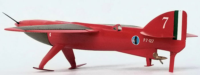
| CONCLUSIONS |
The surface detail is quite nice, but getting the detail to line up across part-seams is a challenge. It appears that the handling of the sprues to get them into the box was rough as some of the detail was marred. I didn’t notice that until the painting was completed. The butt joins are fragile, I broke three pieces while masking and un-masking. The project took about 20 hours to complete.
I still think that for a design some 90 years old, this aircraft looks futuristic, or perhaps something seen in an anime show. The end result is a very nifty looking model.
28 January 2020
Copyright ModelingMadness.com
If you would like your product reviewed fairly and fairly quickly, please contact the editor or see other details in the Note to Contributors.