Dekno 1/48 Spartan 7W Executive
| KIT #: | 480103 |
| PRICE: | $62.00 |
| DECALS: | One option |
| REVIEWER: | John Summerford |
| NOTES: | 3D Printed kit. |
| HISTORY |
Courtesy Mid America Flight Museum
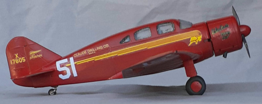
The Spartan 7W Executive model is an all-metal construction with retractable landing gear and fabric covered control surfaces designed and built in Tulsa, Oklahoma. Spartans were built for comfort and performance for both personal and executive businessman. A total of 36 were built between the years of 1936 to 1940 designed by Spartan Aircraft Company and first flight accomplished on March 8, 1936. A couple variants were built for military applications with guns and bomb racks, but was a short-lived program that never gained interest. A total of 16 7W’s were drafted into service and designated as UC-71’s and were used for executive transport for military staff. After 33 years of Spartan Aircraft Company manufacturing aircraft, they sold to Spartan School of Aeronautics, now known as Spartan College of Aeronautics and Technology.
Arlene Davis
Excerpted from Wikipedia.
 Alma Arlene
Davis became interested in flying when her husband bought a plane and she earned
her pilot's license in 1931. She later became the first private pilot to receive
an instrument rating and the first woman to earn her 4M qualification for
piloting multiengine planes. By 1940, she held "more different and difficult
kinds of ratings than...99 out of 100...commercial pilots".
Alma Arlene
Davis became interested in flying when her husband bought a plane and she earned
her pilot's license in 1931. She later became the first private pilot to receive
an instrument rating and the first woman to earn her 4M qualification for
piloting multiengine planes. By 1940, she held "more different and difficult
kinds of ratings than...99 out of 100...commercial pilots".
She soon began participating in air races, winning the first race she participated in (Dayton, Illinois, 1934) as well as the 1936 Miami-Havana International Air Race. In 1938, she was the only woman to take part in the New York–Miami McFadden Race, and in 1939 she finished fifth in the Los Angeles–New York Bendix Race. (The winner, Frank Fuller, flew a P&W Twin Wasp powered Seversky versus Davis’ Wasp Junior powered Spartan.) She finished fourth in the 1946 Halle Trophy Race.
During World War II, she taught instrument flying to Army and Navy aviators at Baldwin-Wallace College. She also served as President Eisenhower's aviation chair for Ohio and was chair of the Office of Civil Defense's Operation Skywatch in the region encompassing Ohio, West Virginia, and Kentucky.
In 1959, she flew 20,000 miles across the North and South Atlantic oceans in her twin-engine Beech Travel Air, with Clay Donges as her navigator. The trip took 13 days and was the first time that a private plane had flown the North and South Atlantic in a single trip.
Flying and Popular Aviation magazine named her America's outstanding woman pilot of "big ships" in 1940. She was the first woman to receive the Veteran's Pilot Award, and the first woman to be honored with the Elder Statesman of Aviation Award. Davis died of cancer in 1964.
| THE KIT |
Dekno has started to produce 48th scale kits by using the 3-D printing process. This kit is one of three variants of the Spartan Executive. (The other kits are of a shiny natural metal with red trim plus a petite Texaco logo on the fuselage and a military olive green over gray UC-71)
 A sturdy
cardboard 7 ½ inch by 4 ½ inch box holds the kit. The label on the lid has a
typo, which yours truly commits frequently, omits the “o” in “Trophy” (I’d like
to buy a vowel Pat….)
A sturdy
cardboard 7 ½ inch by 4 ½ inch box holds the kit. The label on the lid has a
typo, which yours truly commits frequently, omits the “o” in “Trophy” (I’d like
to buy a vowel Pat….)
3-D printing has a reputation for having a rough texture and that is present in some places, notably the wings. 10 bags hold the gray parts and one bag has the clear resin parts. The panel lines are very crisp and might appear too deep for some modelers, but they should look good after painting. Test fitting reveals that some light sanding is needed on mating surfaces. The wings are printed in left and right halves and have an alignment tab to aid their joining. There are no photo-etch parts, so lap belts will need to be sourced. Total parts count is 39.
The decals feel like they are also 3-D printed and are printed on a single piece of carrier film. They are in register and opaque.
A single sheet of paper shows the assembly sequence on one side and the other side has painting and decaling information. There are no color call-outs for the interior and the red for the exterior is not referenced to any brand of paint or FS code. It appears that red called for tilts toward orange. A nice touch is a list of references that are at the bottom of the page, two of which are on-line.
This is my first 3-D printed kit and I was eager to build it.
| CONSTRUCTION |
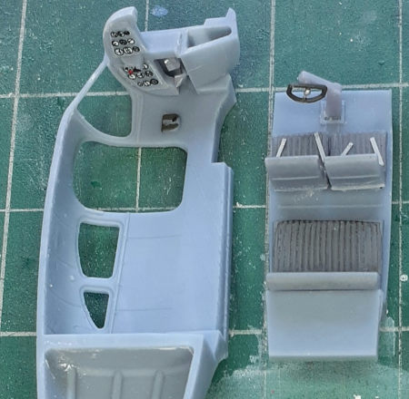
 The interior
of the Executive was upholstered in gray, so there is not a lot of details to
deal with. Even the instrument panel is gray. The sidewalls were left in the
natural resin color and the molded details painted as necessary. The instrument
decals were applied directly to the raw resin panel. Trimming of the carrier
film is needed before application. The seats were sprayed with rattle can gray
primer and washed with diluted black ink. Seat belts for the front seats were
fabricated from card stock.
The interior
of the Executive was upholstered in gray, so there is not a lot of details to
deal with. Even the instrument panel is gray. The sidewalls were left in the
natural resin color and the molded details painted as necessary. The instrument
decals were applied directly to the raw resin panel. Trimming of the carrier
film is needed before application. The seats were sprayed with rattle can gray
primer and washed with diluted black ink. Seat belts for the front seats were
fabricated from card stock.
A dimple is present on the control column for the yoke. This was drilled out for the yoke shaft and the yoke glued in place.
The rudder pedals are glued to the left fuselage half, aft of the firewall. The instrument panel is glued above the pedals.
Returning to the seats, A test fit of their pedestals revealed that some vigorous sanding was needed to get them to fit into their receptacles. After they were glued into place, the control column was added next.
 Realizing
that this is not a “add glue/shake box” build, a test fit of the fuselage halves
revealed that the instrument panel needed some trimming. Slight warping was
detected, leaving a gap along the bottom of the fuselage. This could be closed
with a clamp. The instructions indicate that the cabin interior be trapped
between the fuselage halves, however there is enough room the insert it from
underneath before the wings are offered up. This makes it easier to align the
halves when gluing.
Realizing
that this is not a “add glue/shake box” build, a test fit of the fuselage halves
revealed that the instrument panel needed some trimming. Slight warping was
detected, leaving a gap along the bottom of the fuselage. This could be closed
with a clamp. The instructions indicate that the cabin interior be trapped
between the fuselage halves, however there is enough room the insert it from
underneath before the wings are offered up. This makes it easier to align the
halves when gluing.
The cabin door needed sanding along the lower edge to fit and side edges cleaned up with some light sanding. This was pressed into place and cyano applied to the inside face to secure it to the fuselage.
Before closing the fuselage halves, the cabin windows were installed from the inside. They are cast resin and their clarity invites comparison to bathroom windows. The windows do not have a step around the edges that mate with the steps molded in the inside of the halves, resulting in a poor, recessed fit. The windows were glued in place with gap filling cyano and then flooded with Future floor polish on the outside. This had the added benefit of increasing the clarity of the windows. I’m not sure that chamfering the edges would help the fit.
Contrary to the cabin windows, the windshields are installed from the outside. They sit a little proud at the roof so some sanding their edges was done. Dabs of epoxy were used along the lower edges to secure them and fill some gaps. The windows were treated with liquid masking at this time.
Three different clamps were used to epoxy the halves together After the epoxy cured, the seats were inserted through the bottom. The floorboard snapped into place and no glue or epoxy was needed. The seam needed filling and sanding. As work progressed, the gap at the bottom reappeared, so more epoxy was daubed in the seam and clamped again. This caused some stress around the cabin floor and the fuselage cracked, so that needed cleaning up. The gap should have been filled instead of clamped.
A light sanding with 600 grit sand paper was done to the wings before they were epoxied together. Assuming that the locking tab would create the correct dihedral, it was wedged into the other wing without checking for alignment. When the epoxy had nearly cured, an attempt to induce some dihedral cause the tab to break. After reattaching the wings, a seam was present on the underside and that was filled and sanded.
 A lens for
the light in the underside of the port wing is not supplied. The recess was
painted in chrome and filled with epoxy. Test fitting the wings to the fuselage
revealed that some sanding was needed at the fore and aft edges and gaps were
present on both sides. All of that was easily dealt with.
A lens for
the light in the underside of the port wing is not supplied. The recess was
painted in chrome and filled with epoxy. Test fitting the wings to the fuselage
revealed that some sanding was needed at the fore and aft edges and gaps were
present on both sides. All of that was easily dealt with.
Checking the installation of the horizontal tail pieces showed that the locating tabs were too large in all three dimensions, so they were reduced. A gap was still present and while sanding the filler flush on one, too much pressure was applied and it broke off, requiring a repair.
Attention moved to the nose and the engine was painted. After removing the prop from the casting block, it became apparent that one blade had a shallow “S” shape to it. The concavities were filled with cyano and sanded before painting.
The engine mount is a two-piece affair. Each piece has a square plug to insert into a square recess. Like the seat pedestals, the plugs were too large so more sanding was dome to get a good fit. The cowl fits snugly along the engine rocker covers, so a smear of epoxy was applied just inside the cowl ring to secure it in place. The engine was masked and the liquid mask daubed into the landing gear mounting receptacles in preparation for painting.
| COLORS & MARKINGS |
 It turns out,
I didn’t do nearly enough sanding on the exterior of the model. After a coat of
thick rattle can gray primer, it was easy to see ridges nearly everywhere, so
two more sessions of sanding and priming was done. Thinking this was good
enough, a coat of light sand color primer was sprayed on as a base color for the
red paint.
It turns out,
I didn’t do nearly enough sanding on the exterior of the model. After a coat of
thick rattle can gray primer, it was easy to see ridges nearly everywhere, so
two more sessions of sanding and priming was done. Thinking this was good
enough, a coat of light sand color primer was sprayed on as a base color for the
red paint.
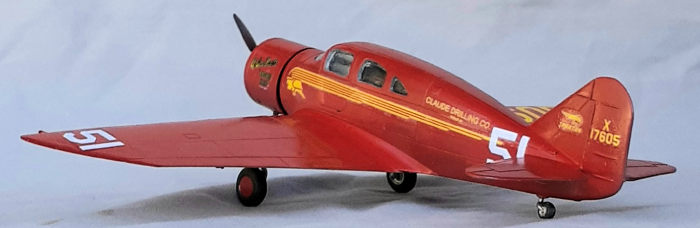
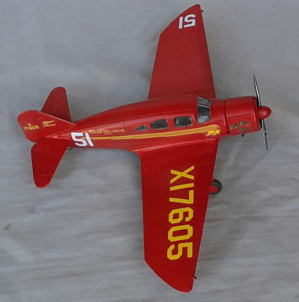
MRP paint was sprayed on and this brand leaves a nice satin finish. In preparation for the decals, as coat of floor polish was brushed on. I noticed that I still had some rough spots, but decided that they were out-of-the-way enough to leave them alone.
After using the decals for the instrument panel, I had some idea as to what to expect for the markings. I knew they were robust and needed to be trimmed as closely as possible. They are so robust that they resist conforming to curved surfaces. I pressed them down with my fingertip to get them to lay down around the cowl and rear fuselage. Creating puddles of Micro Set seemed to help. Forget about them settling down into panel lines.
I also found out that the carrier film is hazy. I accidently let one of the fin decals sit too long in the water and it lifted from the film. I picked it up with a pair of tweezers like it was a contact lens and examined it. It was not damaged, but I could see that the film was not nearly as clear a contact lens. The result is that it looks like the decals have silvered. There isn’t any advice regarding the decals in the instructions and I didn’t find any on the Dekno website. A gloss coat helped to alleviate the look, but it is still noticeable. They did look better the next day.
| FINAL BITS |
Everything was unmasked and I was relieved to see that no touch-ups were needed.
By now, I was not surprised to see that the square tops of the landing gear legs were too large for their receptacles. Again, sanding them resulting a good fit. The wheels and doors followed. The tail wheel is not mentioned in the instructions, but it’s easy to install. I decided to bore out the holes for the exhaust pipes and they dropped into place. The prop installation finished the model.
| CONCLUSIONS |
So, is a 3-D printed kit better or worse than a styrene kit? No, it’s just different. The resin is brittle, so it must be handled differently than cast resin parts or styrene.
The low parts count makes for a relatively quick build, I spent less than 20 hours on this one. I was surprised to encounter the fit issues that I came upon, but they were easy to fix. One needs to be prepared with plenty of fresh sanding sticks and sandpaper. Those who plan on creating a natural metal finish should be prepared for extensive work to create a blemish free surface. I’m guessing that 3-D printing isn’t as easy as one might think and that Dekno is still learning how to use the new technology. There is room for improvement and just resolving the fit issues would help assembly a lot.
The clear parts let this kit down and I think their method of production needs reconsideration. Filling and painting over them with a silver/blue/gray color is a viable option.
If I were I do this one again, I would sand a taper into the bottom face of the wing tab and sand an angle into the mating edges to induce dihedral and that would close the gaps with the fuselage. I would also remove the inner face of the stabilizer locating troughs and enlarge the slots for the tabs.
I also think it would be great if they continued producing Golden Age aircraft such as the Bellanca Pacemaker, Stinson’s Detroiter and Reliant, Curtiss Robin and, (I think it would be wonderful) a Ryan Brougham, which was a follow-on design of the Spirit of St, Louis that could carry six passengers.
18 April 2022
Copyright ModelingMadness.com. All rights reserved. No reproduction in part or in whole without express permission.
If you would like your product reviewed fairly and fairly quickly, please contact the editor or see other details in the Note to Contributors.