| KIT #: | SVM-72015 |
| PRICE: | £ |
| DECALS: | Two options |
| REVIEWER: | Johan deWolf |
| NOTES: |
| HISTORY |
The Falcon 50 is a member of the highly successful series of Dassault biz-jets. Design started after a French government request for a twin turbo fan liason and trainer aircraft for the French air force. Dassault drew upon its experience with the Mystere IV fighter to design a 10 seat aircraft. From the outset Dassault also had an eye on the potential opportunities for the design in the civil market especially in North America.
 The design
was named Mystere 20 and the first flight occurred in the spring of 1963. As
Dassault did not have a sales organisation in the USA, it went looking for a
partner to market the type in North America. It quickly found a partner in Pan
American which was looking for an new aircraft type to launch its corporate jet
aviation division. Using feedback from Pan Am, the design was enlarged, and
different engines were fitted. The reworked design, now known as Falcon 20 first
flew in the summer of 1964. Pan Am ordered 40 machines and took an option on a
further 120. In 1967 the option was converted into a firm order. In the mean
time the type had also been ordered by the French, Canadian and Australian air
forces.
The design
was named Mystere 20 and the first flight occurred in the spring of 1963. As
Dassault did not have a sales organisation in the USA, it went looking for a
partner to market the type in North America. It quickly found a partner in Pan
American which was looking for an new aircraft type to launch its corporate jet
aviation division. Using feedback from Pan Am, the design was enlarged, and
different engines were fitted. The reworked design, now known as Falcon 20 first
flew in the summer of 1964. Pan Am ordered 40 machines and took an option on a
further 120. In 1967 the option was converted into a firm order. In the mean
time the type had also been ordered by the French, Canadian and Australian air
forces.
The design proved highly successful, and many more customers followed. The family was developed further into the smaller Falcon 10 and the larger Falcon 30/40. This last design did not progress beyond prototype stage. However by adding a 3rd engine, new wings and other refinements the Falcon 50 was born. It had its first flight in the autumn of 1976. This type also proved to be a success. To date over 2500 machines of Falcon family have been produced, of which more than 2000 are in active service. Development is still on going, with the latest addition, the Falcon 6X, slated for a production start in 2021.
| THE KIT |
Although
I am not interested in civil aviation. I have always liked the Falcon 20 and
Falcon 50. The shape of these designs just look very appealing to me. Luckily
both types have also several military customers. When Amodel announced it, it
seemed they would only be releasing the biz-jet versions. However when SOVA-M
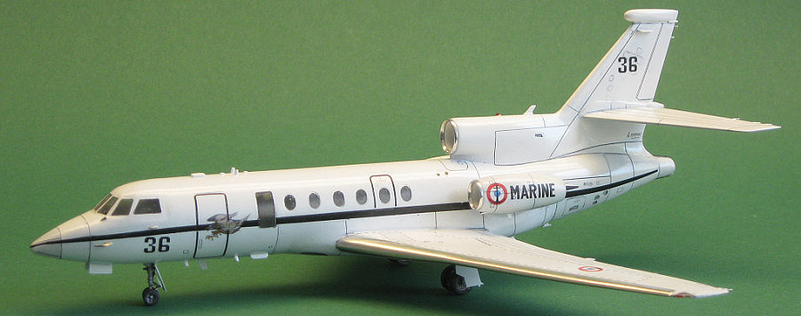
released the same kit with markings for a Falcon 50 Surmar, I just had to have
one. The reasonably sturdy box has a nice picture of a Surmar on final approach
on the cover. It contains 9 light grey and 2 clear sprues. The clear and grey
parts are each packed in their own ziplock bag. Another ziplock has the two
decals sheets and two etched frets enclosed. In total there are 155 plastic
parts of which 10 are marked not for use, and 40 etched parts of which 3 are
marked not for use. Instructions are made up of 6 A4 size sheets . It starts
with a short history, followed by a parts layout diagram. The construction is
then explained in 14 assembly drawings. Finally there is a separate double sided
full colour A4 sheet that shows the placement o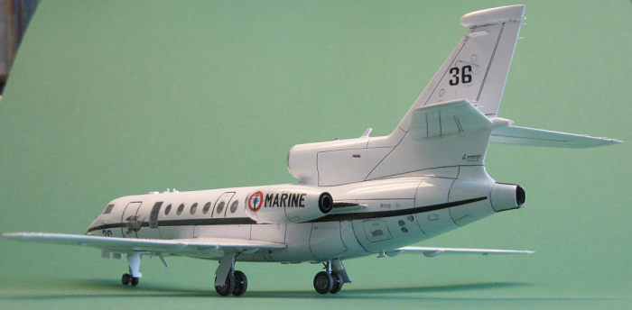 f
the markings for two machines of the French navy. The overall appearance of the
kit is one of good quality. The plastic parts are without sink marks or flash
and mould mismatch is minimal. Ejection towers are few in number and in places
that can’t be seen once the kit is built. Surface detail is by way of finely
engraved lines that are slightly inconsistent in places. The clear parts need a
good polishing, but are not overly thick. That this is not a mainstream kit but
rather a short run one can be gleaned from the somewhat heavy sprue gates of
which some are in awkward places, and the lack of locating pins. Building the
kit will confirm its short run nature, but more on that later. The etched parts
are sharply formed and finely detailed. They concern mainly surface details, and
I doubt the usefulness of them. There are also a few absolutely tiny parts. It
will be interesting to see how these will pan out. The decals are sharply
printed by Decograph and look very nice and thin. The anniversary markings are
on a separate sheet and these are also beautifully printed.
f
the markings for two machines of the French navy. The overall appearance of the
kit is one of good quality. The plastic parts are without sink marks or flash
and mould mismatch is minimal. Ejection towers are few in number and in places
that can’t be seen once the kit is built. Surface detail is by way of finely
engraved lines that are slightly inconsistent in places. The clear parts need a
good polishing, but are not overly thick. That this is not a mainstream kit but
rather a short run one can be gleaned from the somewhat heavy sprue gates of
which some are in awkward places, and the lack of locating pins. Building the
kit will confirm its short run nature, but more on that later. The etched parts
are sharply formed and finely detailed. They concern mainly surface details, and
I doubt the usefulness of them. There are also a few absolutely tiny parts. It
will be interesting to see how these will pan out. The decals are sharply
printed by Decograph and look very nice and thin. The anniversary markings are
on a separate sheet and these are also beautifully printed.
As this is a favourite aircraft of mine I decided I would splash out on some extras. Although the intakes as provided by the kit can be made to look fine, I decided that I would invest in the Mini World intake set (Art.nr. A72 66). This set includes the 3 jet in takes in turned aluminium, and cast brass pitots. To provide some more detail for the cockpit and landing gear I also bought the NH detail etched set for the Falcon 50 (Art.nr. A72-072). This adds another 40 etched parts to what is already included in the kit. It also includes a piece of film with the instrument dials. This set is meant for the civil versions of this kit, but the difference is only in the instrument panels, and only a nut like me would know the difference. To make painting easier, I bought the KV models masking set (Art.nr. 72687-1)
| CONSTRUCTION |
I
started with sanding the mating surfaces of the fuselage halves and main wing
parts to get the best fit possible. Panel lines were then re-scibed for a more
consistent look. First glue was used on the centerline intake duct halves. This
was then dry fitted inside the fuselage halves. I needed to thin down the
fuselage walls a bit to get a good fit. The intake ring as is does not look good
and will need to be reshaped if you are going to use it. I did not bother and
intend to replace the intake ring and first part of the duct with the Mini World
item. So the kit intake duct was cut shorter and the remaining part was glued
into the right fuselage half. The Mini World intake would be fitted after
painting. The cockpit was next. The kit provides 20 parts for this. These parts
are just basic shapes without much detail, there is not even a decal for the
instrument panel nor for the consoles. This is where the etched brass parts from
the NH detail set come in. But first things first. The seats are each build up
from four parts. The NH set added 4 parts for the seat harness to t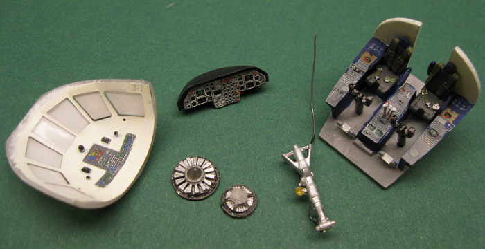 his.
While this was drying the floor was glued to the rear cockpit bulk head followed
by the mid and side consoles. I checked the fit inside the fuselage halves and
this seemed fine, but I forgot the fit the seats. Had I checked this I would
have noticed that the seats would not fit between the consoles where I would
expect them be positioned. The instructions are ambivalent about the position
and the floor is not marked. By looking at pictures on the net I found that the
seats can be adjusted from all the way up to the control column to all the way
back to the bulkhead. This last position is most common when the aircraft is on
the ground, as is makes getting in and out of the seat easier. So disaster
averted, and my seats where glued in at the rear position. To add interest I
glued one of the arm rests in the upward position. The NH brass details for the
console surfaces where added, and these matched the plastic parts perfectly. The
over head switch board was added to the inside of the canopy. The inside of the
canopy was then masked, and the brass parts coated with Mr. Hobby metal primer.
The inside of the canopy and the rear bulkhead where sprayed RAL 9001 (ivory).
When painting the interior, ignore the kit instructions. These are more inline
with the civil aircraft. Look for pictures online for the correct colours for a
Surmar. NH models provides a piece of film with the instrument dials that is to
be installed behind an etched part. As is so often the case, the film was
useless. Either it was a low quality film, or is was exposed out of focus. The
dial faces were reduced to mere black dots. Even painting the rear side white
did not expose more detail. But since I did not have an alternative I decided to
use it anyway. After detail painting the panel was glued into the coaming. The
nose gear bay is made out of 3 parts, but I wonder why, as there is no detail in
it whatsoever.
his.
While this was drying the floor was glued to the rear cockpit bulk head followed
by the mid and side consoles. I checked the fit inside the fuselage halves and
this seemed fine, but I forgot the fit the seats. Had I checked this I would
have noticed that the seats would not fit between the consoles where I would
expect them be positioned. The instructions are ambivalent about the position
and the floor is not marked. By looking at pictures on the net I found that the
seats can be adjusted from all the way up to the control column to all the way
back to the bulkhead. This last position is most common when the aircraft is on
the ground, as is makes getting in and out of the seat easier. So disaster
averted, and my seats where glued in at the rear position. To add interest I
glued one of the arm rests in the upward position. The NH brass details for the
console surfaces where added, and these matched the plastic parts perfectly. The
over head switch board was added to the inside of the canopy. The inside of the
canopy was then masked, and the brass parts coated with Mr. Hobby metal primer.
The inside of the canopy and the rear bulkhead where sprayed RAL 9001 (ivory).
When painting the interior, ignore the kit instructions. These are more inline
with the civil aircraft. Look for pictures online for the correct colours for a
Surmar. NH models provides a piece of film with the instrument dials that is to
be installed behind an etched part. As is so often the case, the film was
useless. Either it was a low quality film, or is was exposed out of focus. The
dial faces were reduced to mere black dots. Even painting the rear side white
did not expose more detail. But since I did not have an alternative I decided to
use it anyway. After detail painting the panel was glued into the coaming. The
nose gear bay is made out of 3 parts, but I wonder why, as there is no detail in
it whatsoever.
Most of the kit supplied etched brass parts are venting louvers. According to the instructions these should be applied to the fuselage skin in several places. This would mean they would stand proud of the surface and it would look very odd. In reality these louvers are flush with the fuselage skin. That is I why I do not understand why this detail wasn’t just moulded. I think they could even have been supplied as decals in this scale. To prevent them standing proud of the surface I used my dremel to machine out shallow recesses. The etched parts where then glued into these recesses flush with the fuselage skin, an any imperfections smoothed out with filler. This took quite a bit of effort as there are 12 of the tiny buggers on the fuselage. There are 4 more on each outboard engine, but I did not bother with these. In most pictures of the real machine these are not visible and I suspect they are closed when the engines are not running.
Next the
cabin windows where installed. The apertures need to be cleaned out a bit, but
then they fit well. I used a cyano glue that was advertised as non fogging.
Sadly it did fog up the windows anyway. I managed to buff out most but in some
windows it is still visible. As there is no interior for the cabin, I masked the
w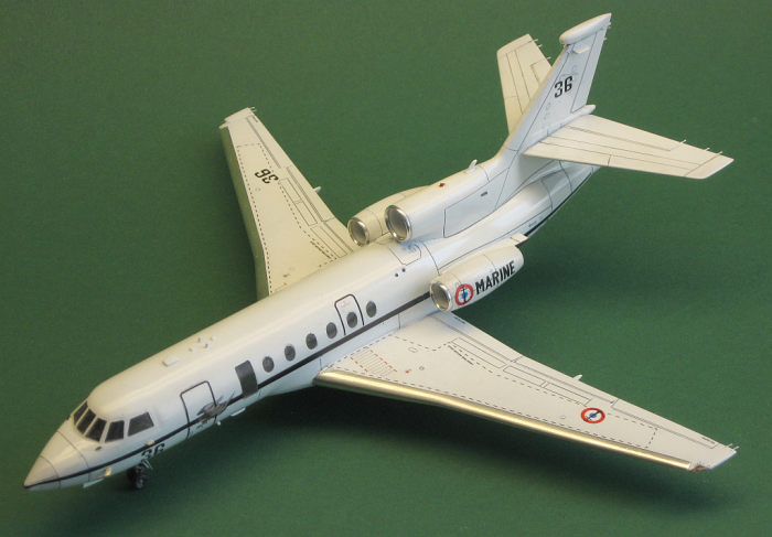 indows on
the inside and painted the interior mat black. As the windows are quite small
nothing much can be seen anyway. The centreline engine exhaust was now tackled.
I used The NH brass here and it looks very convincing, but you will need a
flashlight to see it once the model is completed. With this subassembly done I
had all the parts to complete the interior. The exhaust went in first followed
by the nose wheel bay and the cockpit. The instrument panel was a real pain to
fit as there is no positive guidance or ledge to glue it too. Also the fit was
not great. I had to thin the nose section as much as I dared to be able to get
it in at all. This would not be the last problem with the instrument panel/coaming
as I discovered later. The instructions do not mention a nose weight is needed,
but before permanently glueing the fuselage halves together I did a quick
balance test. This showed that at this stage of construction the model was still
nose heavy. But as a lot of parts still had to be added aft of the main gear,
and not much in front I put in 5-10 grams of lead inside the nose, just to be
sure I would not end up with a tail sitter. This proved to be just enough. The
completed model will sit on its nose gear, but when provoked, it will also sit
quite happily on its tail. That this kit should definitely be considered as a
short run type, was evident from the fuselage halves. One half is slightly
larger in diameter than the other. While at the nose and tail everything lined
up ok, this was not the case on the fuselage roof and the fuselage belly. This
showed a distinctive step that would need attention.
indows on
the inside and painted the interior mat black. As the windows are quite small
nothing much can be seen anyway. The centreline engine exhaust was now tackled.
I used The NH brass here and it looks very convincing, but you will need a
flashlight to see it once the model is completed. With this subassembly done I
had all the parts to complete the interior. The exhaust went in first followed
by the nose wheel bay and the cockpit. The instrument panel was a real pain to
fit as there is no positive guidance or ledge to glue it too. Also the fit was
not great. I had to thin the nose section as much as I dared to be able to get
it in at all. This would not be the last problem with the instrument panel/coaming
as I discovered later. The instructions do not mention a nose weight is needed,
but before permanently glueing the fuselage halves together I did a quick
balance test. This showed that at this stage of construction the model was still
nose heavy. But as a lot of parts still had to be added aft of the main gear,
and not much in front I put in 5-10 grams of lead inside the nose, just to be
sure I would not end up with a tail sitter. This proved to be just enough. The
completed model will sit on its nose gear, but when provoked, it will also sit
quite happily on its tail. That this kit should definitely be considered as a
short run type, was evident from the fuselage halves. One half is slightly
larger in diameter than the other. While at the nose and tail everything lined
up ok, this was not the case on the fuselage roof and the fuselage belly. This
showed a distinctive step that would need attention.
The fuselage was left to dry and I turned my attention to the wings. These consist of a full span lower section, a left and right upper section and separate wing tips with transparent covers for the navigation lights. There are also 4 parts to box in the main gear bays. I needed to sand down the trailing edge of the lower section quite a bit to get a decent fit, but still required filler to get a smooth seam. Once this was done I added the flap actuators. The belly section just in front of the wing is a separate clear part. Dry fitting revealed that this would be a weak spot. I decided to butt join it to the wing section, and then strengthened the join with 2x3mm ribs. After this had dried the landing light tubes and lenses where added. At the rear of the wing section I added a tab to get a more positive fit. Dry fitting revealed that a substantial gap would remain between the fuselage and the top of the wing. To remedy this, the fuselage join on the lower side was separated again. At the front I added a 1mm shim, and the rear needed a 2mm shim. I also needed to remove some plastic to get the wing to sit level. Once I was happy with the fit, the wing was glued in place. Despite all the fettling, I still needed quite a bit of filler to get a smooth surface on the bottom side. The vertical fin is made out of 5 parts. The fin tip electronic fairing was a bit flatter then it should be so I build it up with a bit of filler. Note that this fairing was a later addition, and I am not sure all Surmars have this upgrade. The solid rear facing navigation light was replaced by a clear one. The fin to fuselage join also needed a touch of filler to get a smooth transition.
 The last
opening in the fuselage, except for the jet intake/exhaust, was now the cockpit.
Test fitting the canopy revealed a nasty surprise. The canopy would not fit
properly over the instrument coaming. Even when applying pressure I was still
left with a gap of at least 1mm. The only option was to thin the underside of
the canopy, and the instrument cover as much as possible. In the end I just got
it to fit, but still needed a bit of filler to blend it in properly. I masked of
the jet intake and exhaust, so no dust could get into the fuselage, and sanded
all areas that where treated to filler earlier. Then lost panel lines were
rescribed. At this point the engine pylons were also attached to the fuselage.
The last bits to be added before painting where various antennas and pitots.
Note that these aircraft were upgraded several times, and that not all aircraft
have the same electronics suite. So check your references.
The last
opening in the fuselage, except for the jet intake/exhaust, was now the cockpit.
Test fitting the canopy revealed a nasty surprise. The canopy would not fit
properly over the instrument coaming. Even when applying pressure I was still
left with a gap of at least 1mm. The only option was to thin the underside of
the canopy, and the instrument cover as much as possible. In the end I just got
it to fit, but still needed a bit of filler to blend it in properly. I masked of
the jet intake and exhaust, so no dust could get into the fuselage, and sanded
all areas that where treated to filler earlier. Then lost panel lines were
rescribed. At this point the engine pylons were also attached to the fuselage.
The last bits to be added before painting where various antennas and pitots.
Note that these aircraft were upgraded several times, and that not all aircraft
have the same electronics suite. So check your references.
The outboard engine pods where next. These need to be modified to be able to take the Mini World intake rings. When this was done I only installed the rear bulkhead, part 53, before closing the pod halves. According to the drawings, the compressor face and exhaust cone would need to be fitted first, but I found that by sanding the front end diameter a little bit smaller, the exhaust cone could be fitted after painting. This has two advantages; the inside seam of the engine pod can be cleaned up, and masking and painting will be easier without the exhaust cone being in the way. The exhaust and compressor face were detailed with the NH models etched parts, and especially for the intakes this makes a massive difference, as these are very visible. The compressor face would be glued to the Mini World intake duct later. The engine pods were cleaned up and panel lines rescribed where necessary.
As mentioned earlier, I did not use kit parts P1 (etched louvers). Also I found the auxiliary intake part 59 to be too wide. I scratch built new ones of about half the size. With the engine pods ready, and all the transparent parts masked, it was of to the paint shop.
| COLORS & MARKINGS |
Everything was primed with Vallejo white primer from a rattle can first. This revealed a few uneven spots that were refilled and sanded followed by another priming session. The engine exhaust sections and nose cone where then sprayed with Vallejo off white (70820). Once this had dried these areas where masked of, and the rest of the aircraft was sprayed with several coats of Vallejo RAL9016 white. After several attempts to mask the Mini World engine intakes and failing, I gave up. The intake rings were just too small and smooth for masking tape to adhere to. As a last resort I used a razor saw to separate the intake ring from the intake duct. The intake duct could then be sprayed white. Once everything had dried for a few days, all masking was removed. The KV masks are strong, and were difficult to remove. They had worked a treat though as there was no creepage whatsoever. The panel lines were accentuated with aquarel paint, and then the whole model was coated with Tamiya clear gloss from a rattle can in preparation for decalling.
 When I
picked up the model after a few days to start with the decals I noticed to my
horror that the cockpit windows had all turned opaque. Figuring there was
nothing I could do about it, I just continued with the decals. The decals are
very thin, but can withstand a bit of abuse. Be sure to not let them in the
water for more than one or two seconds though, or they will start to break up.
If decaling is not your thing, my advise would be to cover them with Microscale
Superfilm for added strength. The decals performed without a hitch and without
needing softeners. Beware that the guide contains one major error: The roundel
on the engine pod should be near the intake in both sides of the aircraft. I cut
the cheat line and walkways in several sections to make placing them easier. I
did not use decal 29, as I could not see this marking on pictures of the “36”.
After letting the decals dry for a few days, I wiped the model with a damp cloth
to remove any residue from the decaling process. Then the model received another
coat of Tamiya gloss clear. Weirdly enough this returned most of the clarity to
the cockpit windows. I still have no idea what happened there.
When I
picked up the model after a few days to start with the decals I noticed to my
horror that the cockpit windows had all turned opaque. Figuring there was
nothing I could do about it, I just continued with the decals. The decals are
very thin, but can withstand a bit of abuse. Be sure to not let them in the
water for more than one or two seconds though, or they will start to break up.
If decaling is not your thing, my advise would be to cover them with Microscale
Superfilm for added strength. The decals performed without a hitch and without
needing softeners. Beware that the guide contains one major error: The roundel
on the engine pod should be near the intake in both sides of the aircraft. I cut
the cheat line and walkways in several sections to make placing them easier. I
did not use decal 29, as I could not see this marking on pictures of the “36”.
After letting the decals dry for a few days, I wiped the model with a damp cloth
to remove any residue from the decaling process. Then the model received another
coat of Tamiya gloss clear. Weirdly enough this returned most of the clarity to
the cockpit windows. I still have no idea what happened there.
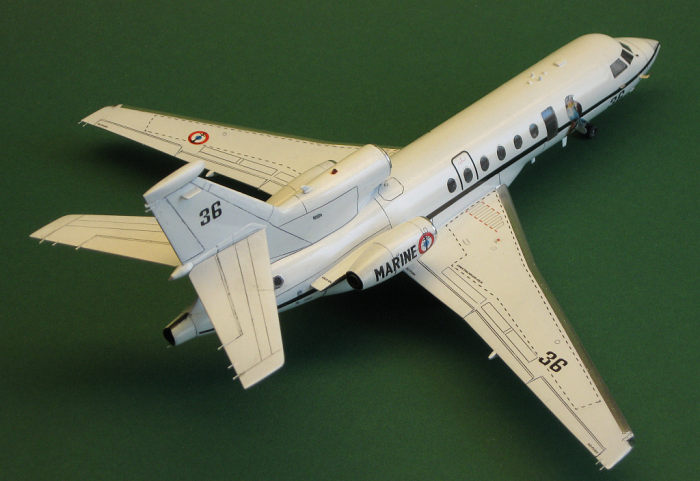
The model was left a few days to dry again, then the main wing leading edges where covered with Bare Metal foil chrome. The engine pods were now finished by installing the exhaust cone and intake duct with compressor face. Then the intake rings were placed. The completed pods could then be fitted on the pylons. Finally on the home stretch it was now time to add the landing gear. As the attachment points are small I used superglue for this task. I used the NH etched parts for the torque links and gear covers. I also added brake lines from thin lead wire. The final parts came from the kit’s etched sheet. These represented the multitude of static discharge wicks. The carpet monsters (oddly enough also present on laminated floors) confiscated their obligatory share. There where no spares, so my model is a few short.
| CONCLUSIONS |
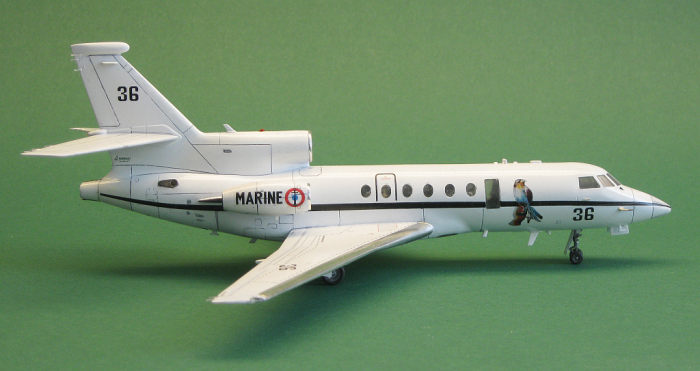
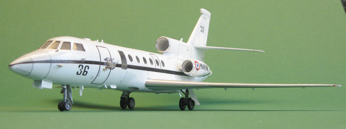
Yes it is an Amodel kit, and very much a short run product. I would say that, although it is more work than a mainstream modern kit, this kit is not overly difficult. If you can handle an old Airfix kit, this one should present no real problems. I am glad I persevered, and the finished model captures the beautiful lines of the real aircraft very well. Amodel is so far the only manufacturer that will release kits of these types of aircraft in injection molded plastic, and I am glad they do. I will definitely build more of these.
The Mini World intakes are definitely worth getting even though they are pricy. The NH details also add a lot of detail. Especially the for landing gear parts and compressor faces they make a massive difference in the look of the finished model. Most of the parts that went into the cockpit are difficult to see though, but I know they are there.
Finally the KV models masks can be recommended. It is a very comprehensive set for all Falcon 50 versions released so far. They are sturdy so they can handle quite a bit of abuse when placing them. Once pressed down they stick like mad, but that is exactly what prevents the paint from creeping under the mask as you see with some other brands.
20 October 2020
Copyright ModelingMadness.com
If you would like your product reviewed fairly and fairly quickly, please contact the editor or see other details in the Note to Contributors.
Back to the Main Page Back to the Review Index Page Back to the Previews Index Page