Dora Wings 1/48 Lockheed Vega 5
| KIT #: | 48024 |
| PRICE: | $40.00 |
| DECALS: | Four options |
| REVIEWER: | John Summerford |
| NOTES: | Some research may be needed |
| HISTORY |
Courtesy National Air and Space Museum
Introduced in 1927, the Lockheed Vega was the first product of Allan Loughead’s Lockheed Aircraft Company and its designer Jack Northrop. It sported a cantilever (internally braced) one-piece spruce wing and a spruce veneer monocoque fuselage (a molded shell without internal bracing), which increased overall strength and reduced weight. A NACA engine cowling and wheel pants reduced drag and provided streamline style.
In 1918, Jack Northrop devised a new way to construct a monocoque fuselage for the Lockheed S-1 racer. The technique called for two molded plywood half-shells that were glued together around wooden hoops or stringers. But to construct the half shells, rather than gluing many strips of plywood over a form, three sets of spruce strips were soaked with glue and laid in a semi-circular concrete mold that looked like a bathtub. This process reduced the time needed from several days down to about 20 minutes. Then, under a tightly clamped lid, a rubber balloon was inflated in the cavity to press the plywood against the mold. Twenty-four hours later, the smooth half-shell was ready to be joined to another to create the fuselage. The two halves were each less than a quarter inch thick.
 Altogether,
the Vega's clean, innovative design made it the aircraft of choice for
record-setters and racers of the era including Amelia Earhart, Jimmie Mattern,
Jacqueline Cochran, and Wiley Post, who became the first pilot to solo around
the world.
Altogether,
the Vega's clean, innovative design made it the aircraft of choice for
record-setters and racers of the era including Amelia Earhart, Jimmie Mattern,
Jacqueline Cochran, and Wiley Post, who became the first pilot to solo around
the world.
Wiley Post
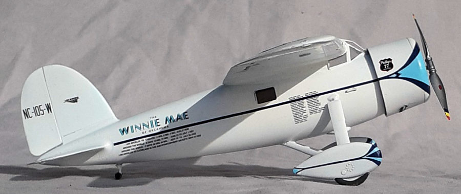
The Winnie Mae, a special Lockheed Model 5C Vega flown by famed aviator Wiley Post, completed two around-the-world record flights and a series of special high-altitude sub-stratospheric research flights. It was named for the daughter of its original owner, F. C. Hall, who hired Post to pilot the plane, which had been purchased in June 1930.
With the consent of his employer, Post entered the Winnie Mae in the National Air Races and piloted the plane to the first of its records, now inscribed on the side of its fuselage: ‘Los Angeles to Chicago 9 hrs. 9 mm. 4 sec. Aug. 27, 1930.’
On June 23, 1931, Post, accompanied by Harold Gatty as navigator, (seated in the cabin aft of the fuel tanks) took off from New York to make a world circuit in record time. The first stop was Harbor Grace, Newfoundland. From there, the fourteen-stop course included England, Germany, Russia, Siberia, Alaska, Canada, thence to Cleveland, and finally to New York on July 1, 1931. The circuit was completed in 8 days, 15 hours, and 51 minutes. Halls admiration for his pilot was displayed when he gifted the Winnie Mae to Post.
Wiley Post spent the following year exhibiting the plane and conducting various flight tests. The airplane was groomed with an overhaul of the engine, and a radio compass and an auto pilot were installed. Both these instruments were at the time in their final stages of development by the Army and Sperry Gyroscope Company.
On July 15, 1933, Post left New York. Closely following his former route but making only eleven stops, he made a 15,596-mile circuit of the earth in 7 days, 18 hours, and 49 minutes.
 Post next
modified the Winnie Mae
for long-distance, high-altitude operation. He recognized the need to develop
some means of enabling the pilot to operate in a cabin atmosphere of greater
density than the outside atmospheric environment. Because of its design, the
Winnie Mae could not be equipped with a pressure cabin. Post therefore asked the
B. F. Goodrich Company to assist him in developing a full pressure suit for the
pilot. Post hoped that by equipping the plane with an engine supercharger and a
special jettisonable landing gear (developed by Lockheed engineers Clarence L.
Kelly’ Johnson and James Gerschler) and himself with a pressure suit, he could
cruise for long distances at high altitude in the jetstream.
Post next
modified the Winnie Mae
for long-distance, high-altitude operation. He recognized the need to develop
some means of enabling the pilot to operate in a cabin atmosphere of greater
density than the outside atmospheric environment. Because of its design, the
Winnie Mae could not be equipped with a pressure cabin. Post therefore asked the
B. F. Goodrich Company to assist him in developing a full pressure suit for the
pilot. Post hoped that by equipping the plane with an engine supercharger and a
special jettisonable landing gear (developed by Lockheed engineers Clarence L.
Kelly’ Johnson and James Gerschler) and himself with a pressure suit, he could
cruise for long distances at high altitude in the jetstream.
His first attempt started on the morning of February 22, 1935 at the Burbank airport, home of Lockheed. After releasing the landing gear, Post turned east. After only half-an-hour, the engine began losing oil and Post had to make a landing with full fuel tanks on the Muroc Dry Lakebed. (Now Edwards AFB) The landing was so smooth that H.E. Mertz, who was perhaps 400 yards away, tinkering on a wind-powered “sail car” did not hear the Winnie Mae touch down. When Post, still in the pressure suit and helmet, walked up to Mertz to ask for help removing the helmets rear wing nuts, Mertz nearly fainted in terror.
An investigation found that the engine was sabotaged by a jealous pilot. The second attempt started on March 15, again from Burbank. Post reached Cleveland, Ohio, a distance of 2,035 miles, in 7 hours, 19 minutes. At times, the Winnie Mae attained a ground speed of 340 mph, indicating that the airplane was indeed flying in the jetstream.
| THE KIT |
The box lid depicts the Winnie Mae in flight but doesn’t identify it or name Wiley Post.
Everything is sealed in a single bag, with the clear parts in their own bag and another containing the decals, photo-etch, and vinyl masks. My example has very crisp molding and detail. Because of the material and construction method used on the Vega, there is not much to show for exterior surface detail, so most of the detail is molded in the interior. The parts are spread across nine sprues and total 70 plastic parts and 11 photoetch.
A 12-page booklet has a cover, parts map, five pages of assembly diagrams, four pages of paint/decal options and the last page a color reference chart calling out Mr. Hobby, Tamiya, Ammo Mig, Hataka. and Life Color paints.
 Construction
starts with the cockpit, moves on to the engine and cowl, then the wheels. The
next seven steps build up the interior, including adding tiny legs to the seats,
then the fuselage is closed up. Wings and tail feathers follow, then the
engine/cowl sub-assembly. The final steps add the windshield then the landing
gear and other underside details.
Construction
starts with the cockpit, moves on to the engine and cowl, then the wheels. The
next seven steps build up the interior, including adding tiny legs to the seats,
then the fuselage is closed up. Wings and tail feathers follow, then the
engine/cowl sub-assembly. The final steps add the windshield then the landing
gear and other underside details.
Decal options are for the Winnie Mae, a Vega flown non-stop from New York to Kaunas, Lithuania by Felix Waitkus, an executive transport for Shell Oil Company, (probably piloted by Jimmy Doolittle at some point during his employment by Shell) and Amelia Earhart’s Vega flown from Hawaii to Oakland. I suspect that, of the four options, only the one in Shell livery had a complete cabin interior.
Here the kit is a bit misleading. The kit is faithful to the reproduction of Wiley Post’s aircraft on display at the Fantasy of Flight in Polk City Florida. However, the Winnie Mae has only two cabin windows—one in the door and the other opposite it. If one wishes to model it as it sits in the National Air and Space Museum, the supercharger intake will have to be scratch built, otherwise it is modeled as before the high-altitude flights.
I’ve wanted to build a decent model of the Winnie Mae for decades. The AMT kit doesn’t do the plane justice, so I’m delighted to have this kit, even if it’s not entirely accurate.
| CONSTRUCTION |
Before gluing any parts together, the cockpit and cabin interiors were painted, then cockpit sidewall detail picked out with washes and artist’s pencils.
Starting with the instrument panel, the first four steps complete the cockpit. When getting to the bulkhead that supports the seat, I found the frame pieces that go above the seat to be very fiddly and only installed two of the three vertical pieces. The illustration is not clear if the horizontal bar overlaps the vertical ones or fits under them. I chose wrong by gluing it on first and then finding that the legs of the vertical pieces are too short. I faked it as best I could. Nor did I bother with the rudder pedals, which are very small and hard to view under the glazing.
Next in the instructions is the assembly of the engine and cowl. I saved that for later when it would be mounted to the firewall. I also delayed building the wheels and spats until painting time. So, skipping forward, the cockpit sidewall pieces were installed.
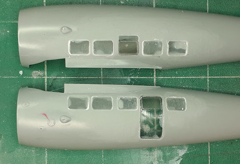 Cabin
assembly is called for in steps 12 through 17. Knowing that there is only one
window under the wing on each side of the cabin of the
Winnie Mae,
I didn’t bother with any of the interior, since it cannot be seen. I did install
the windows on the model and used the vinyl masks on the appropriate ones. All
of the windows were too long, so the sides were filed down. The great thing
about the parts being used as blanking plates meant that I could be sloppy when
gluing them in place. Filling and sanding followed create a smooth fuselage.
Cabin
assembly is called for in steps 12 through 17. Knowing that there is only one
window under the wing on each side of the cabin of the
Winnie Mae,
I didn’t bother with any of the interior, since it cannot be seen. I did install
the windows on the model and used the vinyl masks on the appropriate ones. All
of the windows were too long, so the sides were filed down. The great thing
about the parts being used as blanking plates meant that I could be sloppy when
gluing them in place. Filling and sanding followed create a smooth fuselage.
Before trapping the cockpit assembly between the fuselage halves, I glued the firewall to the cockpit floor and this might have been a mistake. Perhaps it is better to add it after the halves are mated together. I also needed to file down the sides of the bulkheads to get the halves to close. Identifying where to place the cockpit was problematic, since I didn’t attach it to the cabin floor and rear bulkhead. Part G-3 is the interior ceiling and, after trimming the front tab that slots to the seat bulkhead, glued it to the right fuselage half. While the glue was still curing, the left half was taped in place to ensure proper alignment of the piece. This informed me as to where to glue cockpit, and then the fuselage, together.
Since the firewall was in place, the engine was assembled and painted. The instructions call for wrapping the cowl around the engine and glue them, plus the engine mount to the firewall. Looking at the flimsiness of the engine mount, and seeing that the tail and wing hadn’t been attached yet, I was concerned that I could easily knock it off and decided to wait until later to mount this sub-assembly.
Assembling the tail feathers together was a snap. Their mounting holes needed to be enlarged with a 1/16th inch drill bit to get a good fit. Their seams filled easily.
14 plastic parts, eight clear parts and six very small photo-etch parts make up the wing. Only the clear parts fit well. The trailing edges of the upper wing and lover wing pieces don’t mate together. Instead, the trailing edge is molded into the upper piece and the lower wings’ cord fall short, leaving a seam to be filled. A lot of sanding was also done to get the ailerons to blend with the wings. I didn’t bother with the photo-etch pieces.
A test fit of the wing to fuselage had me scratching my head. The upper portion of the bulkhead that supports the seat was too wide by roughly three millimeters on each side. (Really? How did that happen?) My sprue cutters easily removed the excess material. Taking a look ahead at the next step, pieces are inserted in the cockpit covering the gaps at the leading edges of the wings. Good luck with that. It was easier to trim those pieces first and then glue them in place, then attach the wings. Getting the wings level left a gap on one side that needed filling. It’s easy to glue the wings in place out of alignment, so as the glue set, I grabbed my drafting dividers and used the rudder hinge line and a corner of the ailerons as reference points to make sure they were equal.
 When test
fitting the middle (of three) windshield piece, I discovered that I had made a
mistake when mating the fuselage halves. I glued part G15 on top of the
fuselage, thinking that the windshield sits atop it. Instead, I now think, it
goes inside the cockpit opening as coming padding. After sanding the part away,
I got the windshield to fit properly. The side pieces are tricky to install. I
decided to use glue at the aft end, and as the was curing, maneuver into the
final position and flow liquid cement into the seams. It might be best to
install the side windows first, then the middle piece. The vinyl masks provided
are a great time saver and they were applied to protect the clear parts.
When test
fitting the middle (of three) windshield piece, I discovered that I had made a
mistake when mating the fuselage halves. I glued part G15 on top of the
fuselage, thinking that the windshield sits atop it. Instead, I now think, it
goes inside the cockpit opening as coming padding. After sanding the part away,
I got the windshield to fit properly. The side pieces are tricky to install. I
decided to use glue at the aft end, and as the was curing, maneuver into the
final position and flow liquid cement into the seams. It might be best to
install the side windows first, then the middle piece. The vinyl masks provided
are a great time saver and they were applied to protect the clear parts.
Attention turned to attaching the engine. I’m glad I waited until this point because it would have been an impediment if installed earlier. The instructions call for adding the engine mount to the back of the engine and then wrap the cowl around it. Because the cowl overlaps the fuselage, it’s nearly impossible to see where to apply glue and align the sub-assembly.
I chose to install the engine mount first. (The small notch in the engine ring points up.) I was concerned the mount might not be sturdy enough and break off during continued handling, but it proved to be more than adequate. The engine attaches snugly. The three-part cowl was assembled and a test fit revealed that it wouldn’t slide over the engine, so the cylinder heads were sanded down. A couple of drops of liquid cement secured the cowl in place. I didn’t feel in the mood to scratch-build a supercharger intake, so I left the cowl alone and declared the plane being modeled as it was before the high-altitude flights.
Assembling the landing gear struts almost take three hands. It’s great that the sockets are deep enough that one only needs to hold the main strut long enough for the cement to harden sufficiently in order to maneuver the other struts into place. The wheels and spats were assembled, but left off to be painted separately in the next step.
| COLORS AND MARKINGS |
A coat of rattle can white primer revealed where further attention was needed, especially the filled windows. After a final coat of primer, a couple of coats of white paint were sprayed over the entire model.
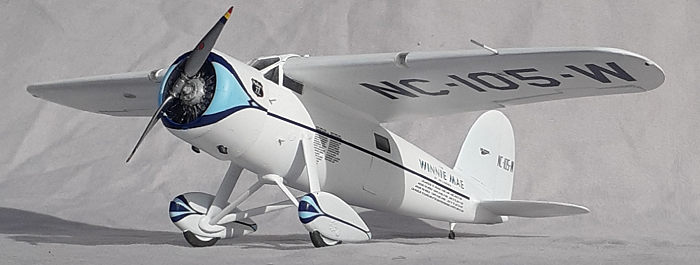
Perhaps the trickiest part
of the build is getting the light blue scallops on the cowl and spats sized and
placed properly. The decals have the dark blue trim that surrounds the light
blue, so they were scanned and the copy was glued to frisket paper to create
templates for the masking. In order to establish where to place the masking, a
one-millimeter-wide strip of tape was laid down alon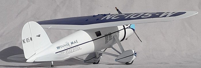 g
the fuselage sides, mimicking the stripe decal. This was also done on the spats,
The tape identified where to decals would be positioned, and thus, where to put
the masks. With some trepidation, the light blue was sprayed on.
g
the fuselage sides, mimicking the stripe decal. This was also done on the spats,
The tape identified where to decals would be positioned, and thus, where to put
the masks. With some trepidation, the light blue was sprayed on.
Dark blue was sprayed on top of the wing. After addressing some minor bleed under the masking, an overcoat of gloss went down for the decals.
The two dark blue trim decals for the cowl were laid down. letting the first one to dry before its counterpart was applied. The decals were easy to maneuver into place. Unfortunately, they didn’t meet together at the cowl face. When both were dry, the fuselage stripes came next, again, each left to dry before moving on. The same sequence was repeated on the spats. Applying the remaining decals was straight forward. Touch-up paint was brushed on where needed. Another coat of gloss sealed everything and the window masks removed.
| FINAL BITS |
The exhaust pipe stubs were inserted through the holes in the underside of the cowl. One stub didn’t attach to the mounting point and fell into the engine, so a piece of rod was glued into the hole and cut to length. The tail skid and wheels followed. Three detail pieces were glued into the fuselage below the canopy. On the right side went the venturi tube. On the left went two climbing pegs for the pilot to get to the cockpit. Those pieces are barely longer than their sprue gates, so I didn’t bother with them and substituted seat legs that were cut to length after they were installed.
That left painting the navigation lights on the wing tips, the pitot tube, and finally the propeller to complete the build.
| CONCLUSIONS |
Dora Wings produces short-run kits, so they don’t just fall together. This is the fifth (sixth if you include a second Caudron) kit from them that I’ve completed and it took the longest at nearly 40 hours, even with the short cuts. I found it helpful to have some previous experience with their kits. I keep comparing it to the AMT kit and, by far, it is more accurate and complicated. I’m annoyed with the size of the seat bulkhead, but it’s easily fixed. When assembling this kit, be sure to look ahead in the instructions and plan your strategy. Be prepared to modify the plan as you go. After all my effort, I’m quite satisfied with this model.
John Summerford
14 July 2022
Copyright ModelingMadness.com. All rights reserved. No reproduction in part or in whole without express permission.
If you would like your product reviewed fairly and fairly quickly, please contact the editor or see other details in the Note to Contributors.