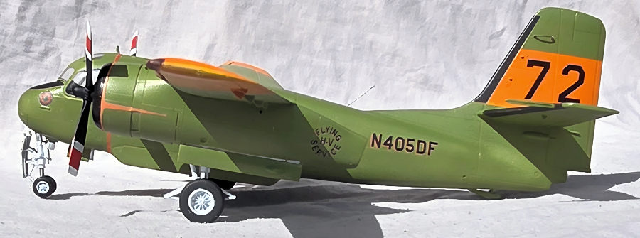
Kinetic 1/48 S-2 Tracker
| KIT #: | K48118 |
| PRICE: | $72.00 |
| DECALS: | Two options |
| REVIEWER: | John Summerford |
| NOTES: | Conversion. Draw decals. |
| HISTORY |
As part of the US Army Air Corps’ expansion after the start of WWII in Europe, it built an airport facility at Hemet, California, which lies in Riverside County, between the San Bernadino mountains on the west and the Colorado river to the east. The airport was activated in March 1941. Claude Ryan, builder of the Spirit of St. Louis, and flight school owner, was contracted to train new cadets. He moved his school from Lindbergh Field, San Diego, to Hemet.
After the War, the contract was cancelled and the airport was handed over to the county and named the Hemet-Ryan Airport. (Ryan opened another airport In Tucson Arizona and it is similarly named.)
 In 1957 the
United States Forest Service (USFS ) began airtanker loading operations at the
airport, and in 1959 the California Department of Forestry (now CAL FIRE)
followed suit. (Yours truly finds this a bit amusing in that these Forestry
agencies decided to make a base where the dominant flora for over 75 miles in
any direction is chaparral, Joshua trees, and various cacti. There may be an
occasional tree near a house, but no forest.) Both agencies maintained separate
parking, loading, and mixing areas. In 1969 the two merged their operations and
named the facility Hemet Ryan Air Attack Base. The joint base continued
operation until 1998 when the Forest Service moved their airtanker base
operation to the larger and recently vacated Norton Air Force Base in San
Bernardino.
In 1957 the
United States Forest Service (USFS ) began airtanker loading operations at the
airport, and in 1959 the California Department of Forestry (now CAL FIRE)
followed suit. (Yours truly finds this a bit amusing in that these Forestry
agencies decided to make a base where the dominant flora for over 75 miles in
any direction is chaparral, Joshua trees, and various cacti. There may be an
occasional tree near a house, but no forest.) Both agencies maintained separate
parking, loading, and mixing areas. In 1969 the two merged their operations and
named the facility Hemet Ryan Air Attack Base. The joint base continued
operation until 1998 when the Forest Service moved their airtanker base
operation to the larger and recently vacated Norton Air Force Base in San
Bernardino.
From the beginning of Hemet Ryan Air Attack base, CAL FIRE and the USFS contracted with owners of World War II era aircraft. The type and sizes of aircraft varied based on the vendor, availability of flyable airframes, and spare parts. As the flight hours increased, these airplanes either became museum pieces or were cannibalized for parts to keep the fleet flying. The equipment problem was eased when CAL FIRE acquired two retired U.S. Navy Grumman S-2A submarine hunting aircraft in 1973. These planes were converted from naval use to firefighters with the engineering and refurbishment done by Hemet Valley Flying Service and were tested by the Hemet Ryan Air Attack Base. The pair were a success and 10 more were commissioned the next year and five more for 1975. The basic aircraft design has been in continuous service since.
In 1996, CAL FIRE acquired 26 S-2E/G planes from the Department of Defense. CAL FIRE converted the planes to a fire-fighting configuration and outfitted with turboprop engines. 12 S-2Ts were ready for the 2001 Fire Season and currently 23 are in operation. The reconditioned S-2Ts are faster, safer, more maneuverable and carry a larger retardant payload than the older aircraft.
| THE KIT |
 Seven bags
hold eight sprues of greenish-gray styrene. One bag holds a pair of duplicate
sprues. Another bag is for the clear parts. There are no photo-etch parts. Total
parts count is 202. Some of the parts are dedicated to the particular variant
being built and they may not be called out in the instructions, so attention
must be paid to the details in the paint schemes. Additional research may be
helpful.
Seven bags
hold eight sprues of greenish-gray styrene. One bag holds a pair of duplicate
sprues. Another bag is for the clear parts. There are no photo-etch parts. Total
parts count is 202. Some of the parts are dedicated to the particular variant
being built and they may not be called out in the instructions, so attention
must be paid to the details in the paint schemes. Additional research may be
helpful.
The Instructions are in a 10-page booklet printed in black and white. They include a brief history, the usual cautions, explanation of symbols, parts map and paint chart for Ammo MIG, Vallejo, Mr. Color, Tamiya and Humbrol paints. Assembly is covered in nine steps. The wings can be assembled folded or extended.
Decals are printed by Fighter Town Decals. They are in register and appear to have good color density. Options are for an S-2N or S-2A, both in the Royal Netherlands Naval Air Service.
| CONSTRUCTION |
Before starting in on the cockpit, the fuselage halves were removed from the sprues, cleaned up and given a test fit. With the halves taped together, a strategy was developed regarding how and when to add the bulge of the retardant tank.
With a plan decided upon, the assembly of the cockpit began. Harnesses for the seats were fabricated from card stock and the instrument panel painted black with the raised detail swiped by a white artist’s pencil.
 A note
to add 50g’s of ballast in nose located in an awkward place in the diagram and
it is easy to miss. There isn’t much room below the cockpit for the weight, so
some of it had to go behind the bulkhead.
A note
to add 50g’s of ballast in nose located in an awkward place in the diagram and
it is easy to miss. There isn’t much room below the cockpit for the weight, so
some of it had to go behind the bulkhead.
In addition to the cockpit, a pair of windows, a weapons bay roof, ventral radome blanking plate, and the tail hook trough were installed in the halves before mating them. The seam around the blanking plate needed several sessions of filling and sanding.
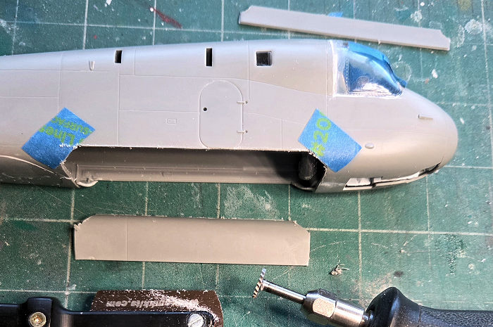
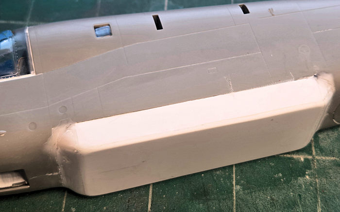
Focusing on the extended retardant tank, the (optimistic) strategy was to make-it-up-as-it-went-along. Starting with starboard torpedo bay door tacked in the extended position, that defined the extent of the bulge of the tank and gave clues regarding building the port side. It would have been nice to have those clues before mating the fuselage halves. It was at this point, the port side for the tank bulge was cut away, which was more difficult to do retroactively, mostly because debris migrated into the cockpit. The bulge was built up with sheet styrene and the joints smoothed with several sessions of cyano filling followed by sanding. The cockpit glazing was masked to protect it from scratches.
 Assembling
and installing the nose gear was called for at this stage but was left for
later. The next step was to assemble the inboard sections of the wings.
Different parts are used for the extended or folded option. Photos found on the
internet did not show any fire fighters on the ground with the wings folded and
those mechanisms were probably eliminated to save weight. The wing extended
parts were sandwiched between the upper and lower wing parts.
Assembling
and installing the nose gear was called for at this stage but was left for
later. The next step was to assemble the inboard sections of the wings.
Different parts are used for the extended or folded option. Photos found on the
internet did not show any fire fighters on the ground with the wings folded and
those mechanisms were probably eliminated to save weight. The wing extended
parts were sandwiched between the upper and lower wing parts.
Next, the engine/landing gear nacelles were assembled. Test fitting revealed that it was best to glue halves together first and then insert the landing gear bays in place from the top. These parts are handed and the test fitting also revealed that instructions mislabel them. Again, the gear legs were left for later, along with the props.
Installation of the inner wings plus the elevators/stabs followed. Fit is very good and needed little filling in the seams.
Building up the outer wings was straight forward. On this variation of the kit, the right wing has a notch in the leading edge for a radar pod. The notch was filled with styrene plates that were glued in place with cyano, then filed and sanded smooth. A panel line was rescribed.
Attaching the outer wings proved to be the most difficult step of the build. The ears of the hinges didn’t slot together, instead, they butted against each other so they were ground off with a rotary tool. Reinforcement ribs are used instead of the folding parts and they needed sanding at their noses to fit inside the wings. The cord of the left outer wing was longer than the inner wing, which meant that the leading and trailing edges required filing to align. There was enough gap in the ribs to induce anhedral at the joint, making gluing a challenge. The seams were ragged and several sessions of filling and sanding followed. When the join was smooth, lost panel lines were rescribed.
Circles of tape covered the engines and bits of foam rubber were stuffed into the wheel bays and the model was ready for painting.
| COLORS & MARKINGS |
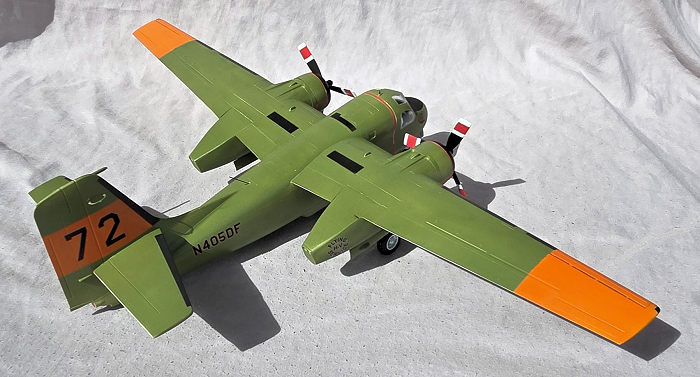
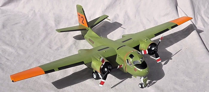
These aircraft sat in the desert sun and present a great weathering opportunity. A photo found on the internet shows this particular subject returning from a mission with very faded paint, exhaust stains on the cowls, and red-color retardant smeared on the belly. I thought briefly about reproducing the effect but decided to go with a simpler first-season rendition.
A rattle-can of white automotive primer was laid down in a couple of sessions – upper and lower surfaces. A mixture of red and yellow acrylic paint was sprayed on the wing tips and vertical tail, then masked. Green base from Mig’s line of Ammo Atom was sprayed, again in two sessions. Instead of painting the de-icing boots, walkways, and anti-glare panel one shade of black, the boots were done in tire rubber and the others flat black after masking over the green coat.
 Before using
a rattle-can of Vallejo’s clear gloss, a few touchups were done and the black
areas masked. The gloss was sprayed more heavily over the areas where the decals
would go and lighter over the rest of the model. The downside to this product is
that, while it is dry to the touch in one hour, it takes at least 24 hours to
cure. During that time, the props were painted.
Before using
a rattle-can of Vallejo’s clear gloss, a few touchups were done and the black
areas masked. The gloss was sprayed more heavily over the areas where the decals
would go and lighter over the rest of the model. The downside to this product is
that, while it is dry to the touch in one hour, it takes at least 24 hours to
cure. During that time, the props were painted.
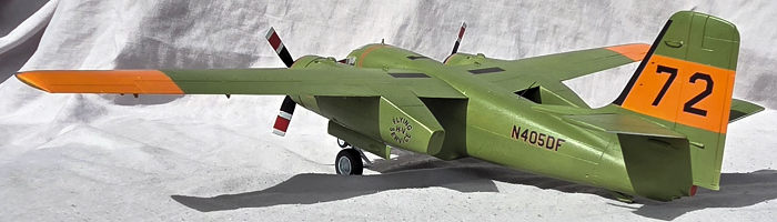
As noted, markings are from Draw Decal. They are thin and printed on continuous film. Applying the letters and numbers were straight forward, but one fuselage registration number lifted of the backing sheet (due to my lack of attention) and getting it uncurled and into place with tweezers and a soaked brush was nerve wracking.
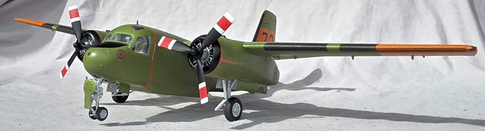
Being much too long, the propeller warning stripes were trimmed before application. Each cowl decal was cut into two pieces, separating the tailing orange strip from the stripes that wrap around each nose. Like the prop warning stripe, the nose stripes are too long, plus, they need more curvature to settle around the cowl properly. Slicing bulges, multiple applications of strong setting solution, and touch up paint made the stripes acceptable. The separated trailing strips were simple to apply.
Once the decals set, the fronts of the cowl rings were hand painted gloss black. With the exception of the antiglare panel, the black areas were unmasked.
Vallejo’s clear matt was misted over the model in two sessions. It’s not completely flat, so the result replicates a slightly weathered factory finish. The glazing and antiglare panel were unmasked and the build continued
| FINAL BITS |
 During the
painting process, the model sat in a cradle and that continued while blade
antennae were installed above and below the cockpit and two antennae glued to
the fin. The landing gear was assembled and installed, followed by the doors.
During the
painting process, the model sat in a cradle and that continued while blade
antennae were installed above and below the cockpit and two antennae glued to
the fin. The landing gear was assembled and installed, followed by the doors.
When the model was set on its wheels, I was horrified to see that the model is a tail sitter. Even though I added 52 grams of ballast as far forward as possible, and dispensed with some of the tail parts, it sits on the rear bumper wheel.
SIGH
Nothing left to do but add the dorsal whip antenna and the props. Maybe I’ll add a clear stand under the bumper or add more ballast in the nose gear well later.
| CONCLUSIONS |
My best guess is to add 55 grams of ballast in the nose. This is a large model when the wings are extended. I measured the span at 17.5 inches. (44.5 cm) Given the problems with the wing hinge parts, folded is the better option.
There are a LOT of extra parts and keeping track of which ones to use for which version is a challenge. I shall use the box to store the extra sprues and add future parts to it.
This project consumed a lot of time (I lost count after 30 hours) and now I have another unusual aircraft in my collection.
It would be nice if someone with a 3-D printer can come out with a conversion set for the turbo prop plane, plus a tank, and revised decals.
John Summerford
18 September 2026
Copyright ModelingMadness.com. All rights reserved. No
reproduction in part or in whole without express permission.
If you would like your product reviewed fairly and fairly
quickly, please
contact
the editor or see other details in the
Note to
Contributors.