Aurora 1/48 Douglas M-2 Mailplane
| KIT #: | 775 |
| PRICE: | $ |
| DECALS: | Two options |
| REVIEWER: | John Summerford |
| NOTES: | Good references a must. |
| HISTORY |
Excerpted from Aurora’s instructions.
 Western Air Express was incorporated on July 13,
1925 and was awarded the contract to fly the mail between Los Angeles and Salt
Lake City. The first flight was on April 17, 1926 using an M-2. Starting at the
home terminal in City of Commerce, southeast of Los
Angeles, that first flight led out over the Mojave Desert to Las Vegas, then on
to Salt Lake City. This 670-mile route, called CAM-4 (Contract Mail Route 4) was
run on a one flight per day basis in both directions. Within five weeks the
first passengers were flown in the front cockpit of the M-2, paying $90 for that
privilege and wearing the flying outfit of a leather suit, cap and goggles. Some
of these early passengers carried mail bags on their laps or draped around their
necks and their only communication with the pilot was by written messages passed
back and forth. The passenger seats were two little folding seats in the mail
compartment and was very similar to riding on a board.
Western Air Express was incorporated on July 13,
1925 and was awarded the contract to fly the mail between Los Angeles and Salt
Lake City. The first flight was on April 17, 1926 using an M-2. Starting at the
home terminal in City of Commerce, southeast of Los
Angeles, that first flight led out over the Mojave Desert to Las Vegas, then on
to Salt Lake City. This 670-mile route, called CAM-4 (Contract Mail Route 4) was
run on a one flight per day basis in both directions. Within five weeks the
first passengers were flown in the front cockpit of the M-2, paying $90 for that
privilege and wearing the flying outfit of a leather suit, cap and goggles. Some
of these early passengers carried mail bags on their laps or draped around their
necks and their only communication with the pilot was by written messages passed
back and forth. The passenger seats were two little folding seats in the mail
compartment and was very similar to riding on a board.
The M-2 was based on the Douglas O-2 military observation aircraft. Cruising at 115 mph with a range of 600 miles, the M-2 was powered by a 415-hp Liberty engine. This plane was built to replace the Postal Department’s old DH-4M’s when they were declared obsolete. After fulfilling the required specifications over its competitors in the government mail plane competition, over fifty M-2s were built.
| THE KIT |
Aurora initially released the kit in 1957 and this boxing is a re-issue with a copyright of 1976. I bought my kit late last century.
Molded
in dark red, there are 32 two hard plastic parts, one of which is a pilot figure
with a huge sink hole. In my boxing, most of the parts were separated from the
sprues. Surface detail is quite nice for the time with a f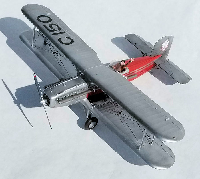 abric effect and
appropriate rivet detail. Another nice addition are discreet nubs at the
locations where the control wires emerge from the fabric. Flash and mold seams
are minimal. The baggage compartments are covered. Unfortunately, a clear
windshield for the cockpit is not included. A test fit of the fuselage halves
shows a tight seam. The fin/rudder, stab/elevator, upper wing and outer lower
wing panels are all single piece units that have molded on control horns.
abric effect and
appropriate rivet detail. Another nice addition are discreet nubs at the
locations where the control wires emerge from the fabric. Flash and mold seams
are minimal. The baggage compartments are covered. Unfortunately, a clear
windshield for the cockpit is not included. A test fit of the fuselage halves
shows a tight seam. The fin/rudder, stab/elevator, upper wing and outer lower
wing panels are all single piece units that have molded on control horns.
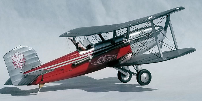
The instructions contain a more extensive history than quoted above, three assembly steps, a rigging diagram followed by a painting and marking guide. The decals appear to be good, though the fuselage stripes are white instead of silver.
Arguably, the single biggest impact on this hobby is the vast amount of information available on the internet. (This site being just one example.) While cruising the web, I found several nits to pick and two errors. The first error is easy to correct. The wiring diagram is flawed, showing single strands between the struts when they are double strands. Also, the location points are on the struts but they should be on the wing structure. The “V” shape wires between the front cabane struts are not shown at all. The second error is much harder to correct. The prop shaft should emerge at the bottom of the radiator, not one quarter of the way up.
As for the nits; Ejector marks are a challenge to overcome and there are sink marks on the fuselage sides, ruining the fabric texture. The cockpit consists of a fictious instrument panel and padded seat with an ejector mark marring the detail. The exhaust stubs are solid and not streamlined, nor do they attach to a long pipe. The upper and lower ailerons are connected by a tube when it should be a rigging cable. Foot rests for the mechanic on both sides of the cowl are not included.
| CONSTRUCTION |
I started by planning where to install the rigging wires. For interewing wires, I prefer to use steel music wire. The thinnest that I can find, courtesy of K & S Precision Metals, is .015 inch and seems to be right for 1/48th scale. Monofilament thread passed under the tip of black felt tip marker makes for good control wires.
 For
the control wires exiting the fuselage and the interplane wires attaching in the
lower wing center section, I shaved off the locating nubs and hand drilled small
holes to the inside surface. Using a rotary tool, the plastic was thinned on the
inside so that a knife blade could elongate the hole on the outside to
accommodate the angle of the wire.
For
the control wires exiting the fuselage and the interplane wires attaching in the
lower wing center section, I shaved off the locating nubs and hand drilled small
holes to the inside surface. Using a rotary tool, the plastic was thinned on the
inside so that a knife blade could elongate the hole on the outside to
accommodate the angle of the wire.
The solid wing panels require a different strategy. The cabane struts and the interwing struts are molded as single piece “U” shaped pairs. The bottom of each “U” sits in a trough in the fuselage or the top of the lower wing. The cabane strut top slides into a trough while the top of the interwing strut has a locating pin that corresponds with a hole. A knife was used to carve notches into the troughs to accept the wires. The top of a pair of interwing struts were laid next the attachment points on the bottom of the top wing and the wire end points were identified. Shallow holes were drilled and elongated.
With that done, all the ejector pin marks and sink depressions were dealt with by a combination of filling, scraping and sanding. Also, while working on the single piece stab/elevators, the hinge line was scored with a scriber and the elevators bent downward.
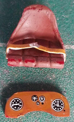 Moving
on to the cockpit, some sidewall detail was added with some strip stock and bits
of styrene to represent a throttle and a box of switches. Instead of using the
raised fictious detail on the instrument panel, the back side was used and it,
plus cockpit interior were painted wood color. Instrument face decals were
sourced from the decal dudgeon. A control stick was fabricated and mounted to
the floor tilted forward to match the droop of the elevators. Lap belts were
also fabricated and glued to the seat. A large sink hole in the pilot figure was
filled and sculpted. The figure was primed and painted with acrylics and is
removeable.
Moving
on to the cockpit, some sidewall detail was added with some strip stock and bits
of styrene to represent a throttle and a box of switches. Instead of using the
raised fictious detail on the instrument panel, the back side was used and it,
plus cockpit interior were painted wood color. Instrument face decals were
sourced from the decal dudgeon. A control stick was fabricated and mounted to
the floor tilted forward to match the droop of the elevators. Lap belts were
also fabricated and glued to the seat. A large sink hole in the pilot figure was
filled and sculpted. The figure was primed and painted with acrylics and is
removeable.
The fuselage was closed up and the seams attended to, followed by attaching the center section of the lower wing. The “U” shaped cabane struts were glued in place and the seam around the bottom of the “U” filled and sanded. The same was done with the interwing struts on the lower wings then glued to the center section.
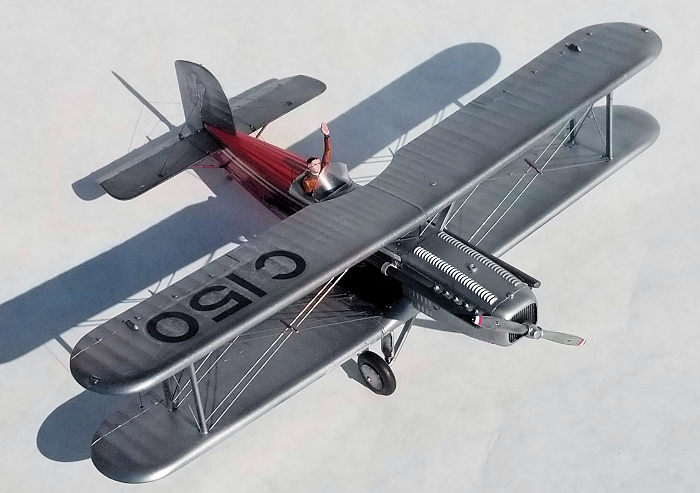
Grooves were filed into the exhaust stubs to cradle the extended exhaust pipes which were fabricated from aluminum tube. The manifold ends of the pipes were slightly crimped and smoothed over with cyano glue followed by sanding. A slight downward bend was made where the pipes passed the rear cabane struts. Mounting brackets were fabricated from paper cardstock.
In order to prepare for painting, all strut, exhaust, and landing gear points, were masked with liquid masking. Tail attachment points were masked with a wedge of scrap plastic for the stabilizer and tape in the fin hole. A sleeve of paper was inserted into the cockpit and filled in with some foam rubber.
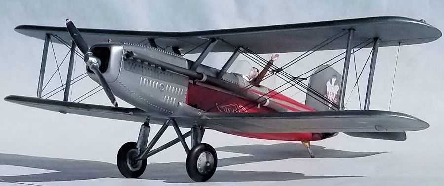
| COLORS & MARKINGS |
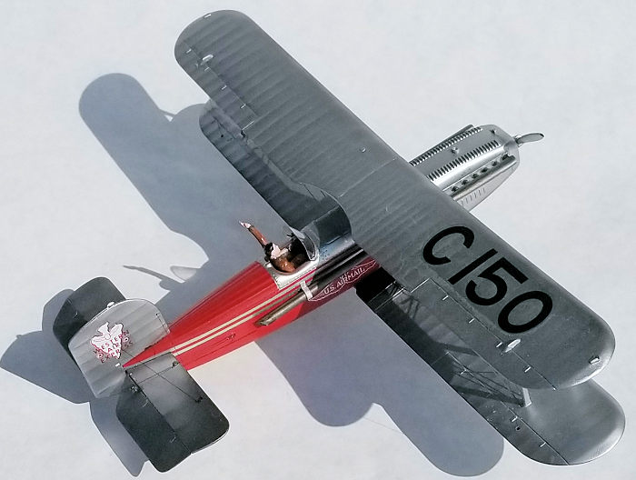 Since
most of plane is aluminum paint, everything was given a coat of Alclad II black
gloss coat. In order to apply the red color, the silver areas were masked,
including the stripes on the fuselage. Since there was near full bottle of
“Guards Red” enamel paint in the rack, I sprayed that on and let the model sit
for a couple of days. (That gave me time to start on another build.)
Since
most of plane is aluminum paint, everything was given a coat of Alclad II black
gloss coat. In order to apply the red color, the silver areas were masked,
including the stripes on the fuselage. Since there was near full bottle of
“Guards Red” enamel paint in the rack, I sprayed that on and let the model sit
for a couple of days. (That gave me time to start on another build.)
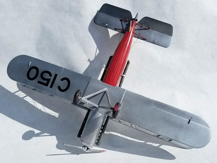
Fully cured, the red was masked, including the space between the stripes. The black wing walks were also masked. Wanting a shiny model, white aluminum was sprayed over the rest of the model plus landing gear, tail feathers, and prop.
Only two tiny touch-ups were needed when the model was un-masked the next day. A wash of black was brushed on the radiator and the wing walks given a brush coat of clear flat.
| MORE CONSTRUCTION |
Opting to apply the decals later, the trickiest steps of the build came next. Thinking that it would be easier at this stage, the exhaust pipes and their mounting brackets were glued in place.
The upper wing was placed upside down and the rest of the model was mated to it. The cabane struts were glued in first, then the interwing struts. Their fit and alignment worked well. An afternoon of rigging with music wire followed.
I glued the horizontal tail in place and in the process, managed to get a drop of liquid cement on the elevator, marring the surface. I masked around the damaged area and re-sprayed the white aluminum. Good as new.
 While
that spot of paint was curing, I spent a couple of hours fabricating the
windshield. I started with a small slip of paper, tracing the shape of the
coaming and cutting it out. After several iterations, I cut a shape out of
cardstock and played with forming the compound curve. A couple of tries later, I
cut a shape out of clear sheet and used a rod to roll the compound curve into
it. I felt good about it after the second try. I masked the bottom edge and
brushed on a black gloss coat, then a silver coat to represent the frame and
also hide the bead of epoxy to attach the windshield.
While
that spot of paint was curing, I spent a couple of hours fabricating the
windshield. I started with a small slip of paper, tracing the shape of the
coaming and cutting it out. After several iterations, I cut a shape out of
cardstock and played with forming the compound curve. A couple of tries later, I
cut a shape out of clear sheet and used a rod to roll the compound curve into
it. I felt good about it after the second try. I masked the bottom edge and
brushed on a black gloss coat, then a silver coat to represent the frame and
also hide the bead of epoxy to attach the windshield.
Moving back to the tail, the fin and rudder piece was glued in place and their decals applied ahead of the rigging. The decals went on easily. The control cables were added to the tail surfaces and ailerons plus the supporting cables in the fin. The tail was completed by gluing on the tail skid.
Comprising four parts plus the wheels, the main landing gear came next. Installation is a little tricky as the struts and shocks need to be installed at once and I got the left set out of alignment, which affected the sit of the model. I cheated by filing some material off of the area where the wheel touches the table top.
The rest of the decals were applied. One “Air Mail” logo split and the “a” in “mail” is marred. I left it alone. I found a couple of red dot decals in the dudgeon and used those as logos for the prop, then glued that in place.
After mixing up a dollop of epoxy, the windshield was set in place and the pilot figure fitted into the cockpit loose, thus completing the model.
| CONCLUSIONS |
A modeler can do a lot worse than this kit. Out of the box, this makes a handsome model and could be assembled quicker than it would take to paint, decal and rig it. There are plenty of opportunities to add detail and stretch one’s modeling skills. I know mine were and I spent about 30 hours doing so. My model club will hold a “Jurassic Plastic” event and I’ll make it my entry.
Being as the first airmail aircraft were the pioneers of today’s airliner networks, I’d love to build more examples, such as a DH-4M, Swallow Mail Plane, and Pitcairn Mailwing. I hope someone does produce those kits.
14 July 2020 Copyright ModelingMadness.com If you would like your product reviewed fairly and
fairly quickly, please
contact
the editor or see other details in the
Note to
Contributors.