| KIT #: | ? |
| PRICE: | $56.00 |
| DECALS: | Two options |
| REVIEWER: | John Summerford |
| NOTES: | Contact the business at Lonestarmodels.com for a possible re-issue |
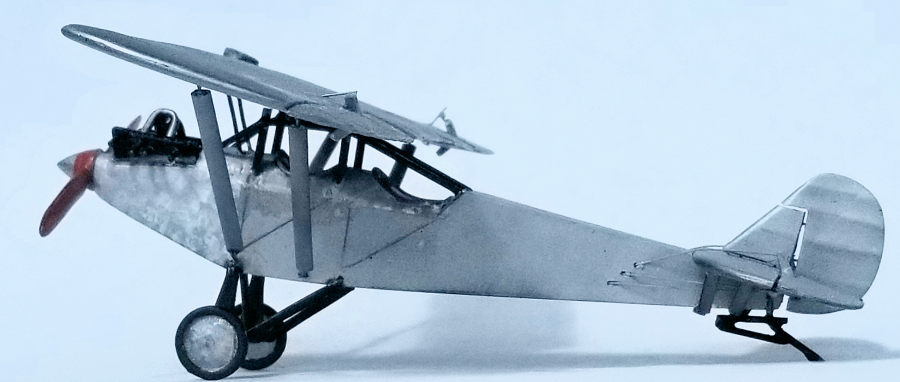
| HISTORY |
Courtesy of The Museum of Flight
 “The
Ryan M-1, dubbed "the plane that pays a profit," was America's first production
civil monoplane and, starting on September 15, 1926, was the first commercial
plane to fly with Pacific Air Transport (PAT) along the West Coast. [Operating
under an air mail contract. Yours
truly] PAT's six M-1s linked
Seattle, Portland, San Francisco, and Los Angeles. The cost was high -- five of
PAT's original M-1s crashed the first year.”
“The
Ryan M-1, dubbed "the plane that pays a profit," was America's first production
civil monoplane and, starting on September 15, 1926, was the first commercial
plane to fly with Pacific Air Transport (PAT) along the West Coast. [Operating
under an air mail contract. Yours
truly] PAT's six M-1s linked
Seattle, Portland, San Francisco, and Los Angeles. The cost was high -- five of
PAT's original M-1s crashed the first year.”
It should also be noted that experience gained from this plane and the follow-on M-2 gave the Ryan Air Lines company the ability to produce Lindberg’s “Spirit of St. Louis”.
| THE KIT |
I
purchased this kit about eight years ago from Lone Star Models’ website and the
parts arrived in the shipping cardboard box bagged and nestled amongst packing
peanuts. Smaller parts were contained in two bags. One bag held small resin
parts which include some cargo boxes and mail bags plus two types of propelle rs
and extra pair of wheels. The other bag contained the metal parts of frame
components, wheel struts, tail skid, and instrument panel frame. The main resin
parts of the fuselage, nose, tail feathers and wing were loose in the box.
Several lengths of airfoil shaped strip stock for struts, some brass tubing for
exhaust stubs, and a decal sheet were the last of the parts. I didn’t find an
instrument panel and also a pair of spreader struts need to be sourced. Total
parts count is 38.
rs
and extra pair of wheels. The other bag contained the metal parts of frame
components, wheel struts, tail skid, and instrument panel frame. The main resin
parts of the fuselage, nose, tail feathers and wing were loose in the box.
Several lengths of airfoil shaped strip stock for struts, some brass tubing for
exhaust stubs, and a decal sheet were the last of the parts. I didn’t find an
instrument panel and also a pair of spreader struts need to be sourced. Total
parts count is 38.
Instructions are printed on an 8 ½ inch by 11inch sheet on the front side and decal placement on the back.
There are several shortcomings. One marking option calls for the words “AIR MAIL” on the top side of the wing. Unfortunately, the height of the letters in the decal is greater than the cord of the wing. Since the words are in block letters, it’s easy to create masks for them. Another is the location of radiator: it should be in the leading edge of the wing over the cockpit. In order to install it there, some surgery will be required and the associated plumbing scratch built. The nose piece appears too short and has a mass of resin between the cylinder banks that needs to be removed and a carburetor and intake manifold installed. In the cockpit, besides scratch building an instrument panel, a throttle and rudder pedals are needed plus a deck over the compartments. The supplied metal framework is incomplete but not worth correcting.
| CONSTRUCTION |
Like all resin kits, the first thing I did was wash all the parts. The wing still felt greasy, so I wiped it with Goof Off. Still not sure of my efforts, I sprayed it with rattle can primer and discovered several areas of fish-eye. Pin holes were also highlighted and I filled them with cyano glue and sanded everything down to get ready for another coat of primer. A notch was created in the leading edge of the wing and the radiator glued into it. Control horns were added to the ailerons and they were glued into place.
Now the hard part began.
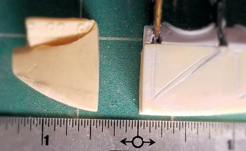 As I tried to
make sense of how the wing and nose mate with the fuselage, I realized that a
plug of about 5/16” was needed to extend the nose. Some of the structure cast
into the forward cockpit needed to be removed as well. Doors on the right side
of the cockpit were not present either, so their outline needed to be scribed in
place.
As I tried to
make sense of how the wing and nose mate with the fuselage, I realized that a
plug of about 5/16” was needed to extend the nose. Some of the structure cast
into the forward cockpit needed to be removed as well. Doors on the right side
of the cockpit were not present either, so their outline needed to be scribed in
place.
One of the nice things about resin is that it is semi-transparent. By holding the fuselage up to the light, I could see the darker molded frame detail and all I had to do was use a pencil to mark where to scribe. After scribing the right side, I noticed that the baggage compartment door on the left side was incorrect and filled in its outline and re-scribed it.
That done, I removed the casting plug from the nose by wet sanding with 220 grit paper on a flat surface. The same followed for the front of the baggage compartment. Lining those two pieces up revealed that the white metal frame piece is miss-shaped and needed to be re-aligned, but how much was yet to be determined.
Looking further at how the frame pieces fit, I noticed that they are a butt join
on the top of the sill. Not trusting the strength of this attachment, I decided
to run brass rods from the cockpit floor into the bottom of the wing. In order
to accommodate the rods, notches were cut into the molded framework. I cut the
brass pieces over-long to protrude past the top of the white metal framework and
glued them in place.
 With the
wing upside down, the fuselage was laid in place to identify were to drill the
receiving holes. It turns out I didn’t get the center line of each component
lined up and had to elongate the holes. I’m glad I double checked at this stage
rather than later.
With the
wing upside down, the fuselage was laid in place to identify were to drill the
receiving holes. It turns out I didn’t get the center line of each component
lined up and had to elongate the holes. I’m glad I double checked at this stage
rather than later.
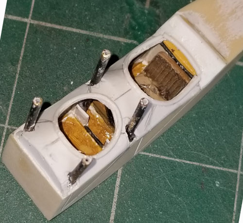
An instrument panel plus rudder pedals were fabricated and glued in place. Another form in the same shape as the instrument panel was glued to the front of the baggage compartment. The panel and former were used to shape the main deck part of the forward fuselage made from .020 styrene sheet. Oval openings were traces onto the deck and notches cut out so that the deck could fit in place. Clamps were used to hold the deck while glue was curing. When that set up, I got out my rotary tool, reminded myself to breathe, and carefully cut out the openings in the deck. For the much smaller aft deck piece, I needed two tries to form a piece. I have new appreciation for the sheet metal guys’ ability to form complex shapes.
After painting, the seat and control stick were glued into place followed by the aft deck piece. Filler and filing plus sanding resulted in the final shape. The final addition in this area was “padding” around the openings. Styrene .030” quarter round strip stock was coiled around the handle of one of my knives to pre-form the shape. (I’ll trust the good folks at Evergreen Scale Models to confirm the cross section. My vision isn’t good enough tell.) Small sections were glued in sequence and trimmed to fit. A little bit of putty on the inside edge and then sanding followed. The door lines were scribed into the deck and padding.
Returning to the nose, it became apparent that the alignment issue wasn’t nearly as bad as I thought. The gap still needed to be addressed, but the bottom lined up much better to the fuselage. Its shape still needed refinement.
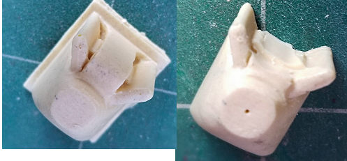 The
mass between the cylinder heads was removed and that area cleaned up. Holes were
drilled for the exhaust stubs. A pair of formers, slightly undersized to accept
.010 sheet skin, were cut out of .060 sheet. One was glued to front of the
cockpit and the other glued to the back of the engine. The skin was cut as a 3/8th
inch wide strip and wrapped around the engine former, leaving the bottom open
for more structure if needed. That assembly was trimmed a bit after test fitting
to the fuselage.
The
mass between the cylinder heads was removed and that area cleaned up. Holes were
drilled for the exhaust stubs. A pair of formers, slightly undersized to accept
.010 sheet skin, were cut out of .060 sheet. One was glued to front of the
cockpit and the other glued to the back of the engine. The skin was cut as a 3/8th
inch wide strip and wrapped around the engine former, leaving the bottom open
for more structure if needed. That assembly was trimmed a bit after test fitting
to the fuselage.
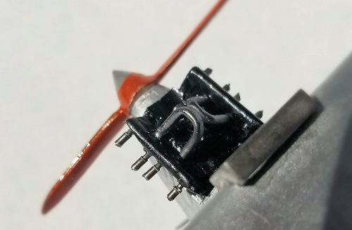
Before mounting the nose to the fuselage, the intake manifold was formed by bending two bits of brass wire into “U” shapes and mounting holes drilled into the cylinder heads. An air intake was created out of plastic tube and glued between the heads. Glued to the top of the intake was a disc punched out of sheet styrene, hoping it looked carburetor-ish. The intake manifold pieces were glued into place atop of the “carburetor”. The exhaust stubs were left for later.
When the glue had cured, the nose was offered up to the fuselage and sanded to shape. That required several sessions of filling and sanding.
The
landing gear was tackled next. The white metal pieces supplied are inaccurate,
but I decided to uses them as is. Using a pair of dividers, the mounting points
for the main struts and “V” strut/axle were identified and then drilled out. The
“V” strut hole was elongated with a rotary bit. Going back to the drafting
tools, a grid of two lines was drawn on paper and a “V” bent from brass rod was
laid upon it. Using a compass, the distance from the
 point of the
“V” where it mounts on the fuselage to axle hole on the main strut was
determined and transferred to the paper. This determined where to bend the rod
symmetrically to create the axles of the part. It took several tries to get
everything lined up and glued in place. It’s not accurate, but it is strong and
the sit is level.
point of the
“V” where it mounts on the fuselage to axle hole on the main strut was
determined and transferred to the paper. This determined where to bend the rod
symmetrically to create the axles of the part. It took several tries to get
everything lined up and glued in place. It’s not accurate, but it is strong and
the sit is level.
After that, adding the tail skid was a snap.
Before moving on to the tail parts, locations for the control cables were determined and drilled out. After the tail parts were removed from their casing blocks, witness marks were drawn across the hinge lines to indicate where to drill holes for the mounting pins that would be use to re-attach the rudder and elevators. The holes were drilled and slots cut put for the control horns. With all the material removed, everything was glued into place starting with the horizontal pieces. A slip of .015 plastic was used to act as a spacer to get and appropriate sized gap along the hinge lines while the glue set up.
Thinking it would be neater at this stage, the control cables were added next. They were made from strands of braded copper wire from an old extension cord and straightened out by rolling them between a steel ruler and piece of glazed tile. I found this easier to work with than monofilament thread.
Mounting points for the wing and tail struts were masked with latex. Slips of rolled paper were placed in the cockpit and cargo hold and bits of foam rubber were wedged in to mask those areas. It was off to the paint booth.
| COLORS & MARKINGS |
 A light coat
of automotive primer from a rattle can was sprayed over everything followed by
Alclad II black gloss base. A little bit more of filler and sanding was done and
another coat of black was applied. The cylinder covers were masked. In order to
get a good contrast with the brushed aluminum cowl and deck, dull aluminum
sprayed on everything.
A light coat
of automotive primer from a rattle can was sprayed over everything followed by
Alclad II black gloss base. A little bit more of filler and sanding was done and
another coat of black was applied. The cylinder covers were masked. In order to
get a good contrast with the brushed aluminum cowl and deck, dull aluminum
sprayed on everything.
The fabric was masked and brushing of the metal areas was done with a very trimmed craft brush and Vallejo chrome. The twisting motion I used isn’t very apparent. Up close it looks more like a mottle. I did find that the small puddle I was using to dip the brush in worked better as the paint became thicker as it dried. I have the Revell Spirit of St. Lois model on my shelf and I think the paint technique is much better than the decal Revell supplied.
The decals are oversized and the carrier film covers the whole sheet. A piece of scrap was used a test and it revealed some fragility. I didn’t realize how much until the first try at the rudder decal bunched up on itself, so skipped them all together.
| FINAL CONSTRUCTION |
 Brass rod
was used to represent the frame pieces that connect the top of the cabane struts
to the fuselage. Starting at the back of the cockpit and working forward, the
rods were bent as need and glued in place with cyano. They were painted gloss
black as well the cabane struts and landing gear.
Brass rod
was used to represent the frame pieces that connect the top of the cabane struts
to the fuselage. Starting at the back of the cockpit and working forward, the
rods were bent as need and glued in place with cyano. They were painted gloss
black as well the cabane struts and landing gear.
Also cut from brass rod were the exhaust stubs. After being glued in place, they were painted exhaust black.
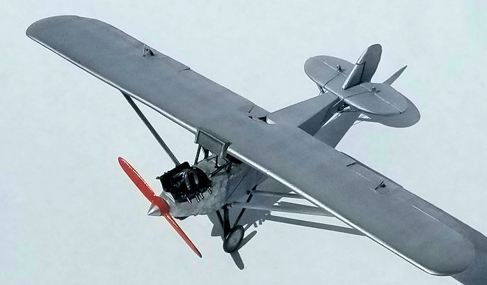
With some apprehension that I might have screwed up somewhere, the wing was attached to the cabane struts with epoxy to allow time for adjustments and strength. Turns out everything lined up with the grid on my modeling pad.
Struts for the stabilizer and wing were measured, cut and glued in place. The wheels came next. Turning the model over, plumbing for the radiator made from rod was installed. The final addition was the propeller.
| CONCLUSIONS |
Lone Star Models is a one-man operation and some aspects of the kit are inaccurate, but credit has to be given for producing it. I’m delighted to have this model on the shelf, more so given the amount of time spent on it. At over 45 hours, it’s easily the most time that I’ve spent to build a model of this size.
My previous build was also a mail plane—the DouglasM-2. I concluded that review by asking for more mail plane kits to build because they represent important aviation history. I'm repeating the request for a DH-4M, Swift Mail Plane in Varney Air Lines Livery and a Pitcairn Mailwing.
4 August 2020
Copyright ModelingMadness.com. If you would like your product reviewed fairly and fairly quickly, please
contact
the editor or see other details in the
Note to
Contributors. Back to the Main Page
Back to the Review
Index Page
Back to the Previews Index Page