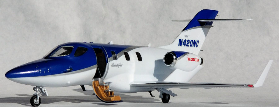
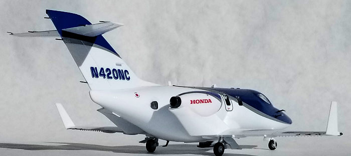
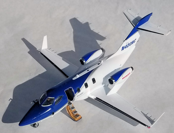
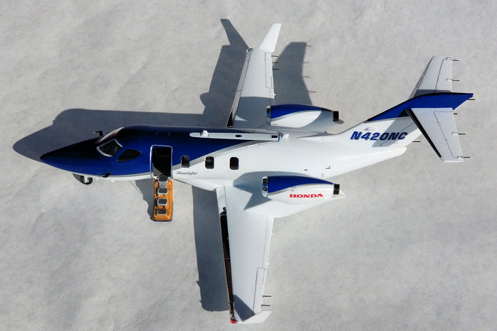
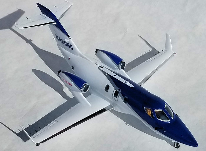
Ebbro 1/48 Honda Jet
| KIT #: | 48001 |
| PRICE: | $65.00 |
| DECALS: | Two Options |
| REVIEWER: | John Summerford |
| NOTES: |
| HISTORY |
 Honda’s aviation
subsidiary began work on business jet and engine combination in 1997. The first
flight occurred in December 2003 (100 years after the Wright brothers) and FAA
certification was granted in December 2015. Key design elements are the use of
composite material construction and the engines mounted over the wing instead of
on the fuselage. This results in roomier, quieter cabin. The Honda HF120 engines
were developed with GE. The jet cruises at 485 MPH and has a range of 1400
miles.
Honda’s aviation
subsidiary began work on business jet and engine combination in 1997. The first
flight occurred in December 2003 (100 years after the Wright brothers) and FAA
certification was granted in December 2015. Key design elements are the use of
composite material construction and the engines mounted over the wing instead of
on the fuselage. This results in roomier, quieter cabin. The Honda HF120 engines
were developed with GE. The jet cruises at 485 MPH and has a range of 1400
miles.
| THE KIT |
 All of the sprues are
bagged separately. The two main sprues are molded in white, one sprue in clear
and the final one of chromed parts for the lading edges of the engine nacelles
plus the leading edges of the wings and stabilizer. One nit to pick is that the
chrome will be removed at the gate on the outer end of the wing pieces. However,
that gate is on the bottom side and between two close panel lines, so it should
be easy to paint or foil over.
All of the sprues are
bagged separately. The two main sprues are molded in white, one sprue in clear
and the final one of chromed parts for the lading edges of the engine nacelles
plus the leading edges of the wings and stabilizer. One nit to pick is that the
chrome will be removed at the gate on the outer end of the wing pieces. However,
that gate is on the bottom side and between two close panel lines, so it should
be easy to paint or foil over.
The final two pieces are the top of the flight deck/forward cabin. You have your choice of red or blue plastic. The decal sheet includes cheat lines to cover the seam. Total parts count is 81 pieces plus the decals. There are no photo-etch pieces.
The instructions are on a three-fold sheet and consist of 10 steps. The Illustrations are similar to Hasegawa and Tamiya with notes in Japanese and English. Color call-outs are for Tamiya paints.
| CONSTRUCTION |
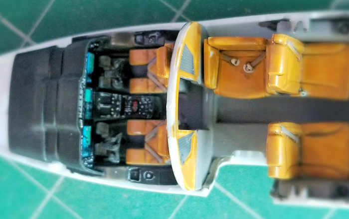
I started by painting and decaling all of the interior parts—including the blue cabin roof. The glass cockpit makes it easy to “do” the instrument panel. It’s basically a decal. I did find that the decal was robust, but difficult to maneuver into place, perhaps because of the raised detail. I filed that observation for later. I assumed that most of the cabin detail would be hidden. It is worth paying attention to the flight deck due to the large windows. A wash of India ink thinned with a drop of detergent added to the bottle was applied to the seats and the cockpit details picked out with a swipe from a white artist’s pencil.
 I glued the
parts in place starting with the rudder pedals and worked up and aft. After the
interior was completed, the lower fuselage was joined. Most of the seam clean-up
was on the bottom.
I glued the
parts in place starting with the rudder pedals and worked up and aft. After the
interior was completed, the lower fuselage was joined. Most of the seam clean-up
was on the bottom.
This got me through the first three steps. The fourth step calls for gluing all the parts onto the cabin roof and then to the fuselage. I decided to wait and assemble the rest of the airframe and check to see if it needed any ballast in the nose.
Step 5 is the assembly of the tail surfaces. This calls for applying the decal on the fin, which means pre-painting white. Looking further at the roof assembly in step 4, I noticed that a trim decal is applied before the antennae, so pre-painting is required there as well. I decided to paint the roof and set it aside. The fin/rudder were glued together, then to the fuselage. I moved onto the next two steps which call for assembling the engines and wings.
While working on flying surfaces, I sandwiched the molded on static discharge wicks between bits of cardstock to protect them from damage. Also, I noticed that the engine pods are mislabeled as left or right. Fortunately, the pylons are keyed and cannot be installed incorrectly.
After the paint on the roof cured, I installed the windows and left the antennae and probes on the outside for later. I did a test fit of the assemblies to see if the model is a tail sitter. With just a nudge, it sat on the tail bumper, so I added several grams of lead in the nose. After that, I glued on the roof and masked it. The wings (minus the chrome leading edges) were glued in place next. The fit is so good that there was nothing clean up, so the engine pylons were glued on followed by the fin/rudder. Then it was off to the paint booth.
| COLORS & MARKINGS |
Some of the cabin windows
extend below the color line, so they were masked with latex. I made a paint
stand out of a scrap of wood and two 1/16th inch steel rods spaced wide enough
apart to line up
 with the engine nacelles. I wedged bits of packing foam into
the nacelles and eased the model onto the rods. The model was wiped down with
rubbing alcohol and a coat of gloss white enamel thinned 40% paint to 60%
thinner was sprayed on.
with the engine nacelles. I wedged bits of packing foam into
the nacelles and eased the model onto the rods. The model was wiped down with
rubbing alcohol and a coat of gloss white enamel thinned 40% paint to 60%
thinner was sprayed on.
The masking was removed and the decals were applied, starting at the tail. In order to avoid rubbing the decals out of position, I applied them over four sessions. The three most difficult decals are the two on the top of the nacelles and the door frame. For the former, consideration should be giving to slitting the leading edge at least once or perhaps twice and at least two places on both sides. The slits should be at least ¼ inch. I managed to get the decals snug on the nacelles after several passes with a razor blade and multiple applications of Solvaset.
The door frame decal is easy to apply if the door is closed because there is very little carrier film inside the shape. With the door open, I used a brush loaded with water and a toothpick plus a lot of patience to tease it into position. It would probably be easier to cut the decal into two sections at opposite corners.
I discovered three extra silver trim decals plus a few other without any indication where they should go. The front right trim decal is identified by two different numbers.
| FINAL CONSTRUCTION |
 The horizontal tail
surfaces were assembled and glued into place without any fuss. The chromed
leading edges of the nacelles came nest. They cannot be removed from the sprue
without leaving a nub of bare plastic. This gave me a chance to try using a
Liquid Chrome marking pen that I recently purchased. It works so well that I
cannot detect the sprue gate.
The horizontal tail
surfaces were assembled and glued into place without any fuss. The chromed
leading edges of the nacelles came nest. They cannot be removed from the sprue
without leaving a nub of bare plastic. This gave me a chance to try using a
Liquid Chrome marking pen that I recently purchased. It works so well that I
cannot detect the sprue gate.
The door was assembled and while the paint was curing, the leading edges of the wings were installed. Again, the chrome touch-up worked great. Returning to the door. The decals for the treads were applied and when they dried, a coat of clear flat was brushed over them.
Attention next was paid to the underside. In addition to the landing gear, two windows (a feature that I don’t understand) and an antenna were added. The main gear was built up with the part that holds the wheel door, then glued in place followed by the retracting arm. Wheels and doors followed. The nose gear and its door slot in place nicely.
After placing the model on the wheels, the antennae on the roof and nose probes were added. One static discharge wick was repaired and all of them were painted. The door was glued in place and I added a hand grip cable made from a strand of copper wire. When the glue cured, I declared the model completed.
| CONCLUSIONS |
This is not a complicated build but still requires some patience. There are some errors in the instructions, however they are all minor. I completed this model in less than 20 hours and I’m pleased to have a nice, shiny model to place on the shelf.
28 April 2020 Copyright ModelingMadness.com If you would like your product reviewed fairly and fairly quickly, please contact the editor or see other details in the
Note to
Contributors. Back to the Main Page
Back to the Review
Index Page
Back to the Previews Index Page