Sharkit 1/48 Rutan Long-EZ
| KIT #: | |
| PRICE: | $90.00 |
| DECALS: | None |
| REVIEWER: | John Summerford |
| NOTES: | Limited edition (2014) 1/48 scale resin kit |
| HISTORY |
Courtesy of Wikipedia
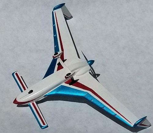
 “The Rutan
Model 61 Long-EZ is a homebuilt aircraft with a canard layout designed by Burt
Rutan's Rutan Aircraft Factory. It is derived from the VariEze, which was first
offered to homebuilders in 1976. The prototype, N79RA of the Long-EZ first flew
on June 12, 1979.
“The Rutan
Model 61 Long-EZ is a homebuilt aircraft with a canard layout designed by Burt
Rutan's Rutan Aircraft Factory. It is derived from the VariEze, which was first
offered to homebuilders in 1976. The prototype, N79RA of the Long-EZ first flew
on June 12, 1979.
The aircraft is designed for fuel-efficient long-range flight, with a range of just over 2,000 miles (3,200 km). It can fly for over ten hours and up to 1,600 miles (2,600 km) on 52 gallons (200 liters) of fuel. Equipped with a rear-seat fuel tank, a Long-EZ has flown for 4,800 miles (7,700 kilometers).
The pilot sits in a semi-reclined seat and controls the Long-EZ by means of a side-stick controller situated on the right-hand console. In addition to having an airbrake on the underside, the twin tail's wing-tip rudders can be deflected outwards to act as auxiliary airbrakes.”
| THE KIT |
 Small subjects make for small models. This kit comes in a top opening
corrugated box measuring on the outside 7 3/8th inches long by 4 5/8th inches
wide by 1 5/8th inch high. Inside is some padding and a zip top bag holding the
31 parts and 7 by 8-inch sheet of paper printed on one side with a parts list
and a truncated three-view drawing. A single vac-formed canopy on a male plug is
also included. I like having the plug, as it helps with cutting off the excess
material.
Small subjects make for small models. This kit comes in a top opening
corrugated box measuring on the outside 7 3/8th inches long by 4 5/8th inches
wide by 1 5/8th inch high. Inside is some padding and a zip top bag holding the
31 parts and 7 by 8-inch sheet of paper printed on one side with a parts list
and a truncated three-view drawing. A single vac-formed canopy on a male plug is
also included. I like having the plug, as it helps with cutting off the excess
material.
I didn’t detect any bubbles, but there are some rough surfaces and mold release agent on some of the parts. A test fit of the upper and lower fuselage halves plus a wing to fin/rudder piece revealed them to be very good. There is zero detail in the cockpit save for a pair of seats and an instrument panel that shows a questionable layout. The landing gear is not reinforced, so I suspect the legs are easy to break. The ID numbers will have to sourced form a spare decal sheet. There is no factory paint scheme, so you can get creative with the finish.
| CONSTRUCTION |
All the parts were washed in a solution of bathroom cleaner, detergent
and water, scrubbed with a toothbrush. With no step-by-step instructions to
deviate from, I had to give this some forethought. There is no indication of
exactly where the front seat and instrument panel fit, so I set about to discern
those placements. That
 meant cutting the upper and lower fuselage halves from
their pour stubs and checking their fit. I ran the mating surfaces over 400 grit
wet/dry (used wet to keep the dust down) taped to flat piece of plexiglass and
discovered a very good fit. I also then understood the width of the ledges that
run the length of the cockpit. A search of the internet reveals that there is
not much to these cockpits, so I decided to add just a throttle/fuel mixture
lever assembly on the left and the side controller on the right.
meant cutting the upper and lower fuselage halves from
their pour stubs and checking their fit. I ran the mating surfaces over 400 grit
wet/dry (used wet to keep the dust down) taped to flat piece of plexiglass and
discovered a very good fit. I also then understood the width of the ledges that
run the length of the cockpit. A search of the internet reveals that there is
not much to these cockpits, so I decided to add just a throttle/fuel mixture
lever assembly on the left and the side controller on the right.
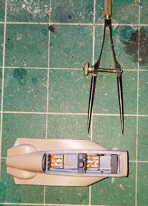
Where to locate them? I taped the fuselage pieces together and cut the pour stubs from the seats and placed them in the tub. The back seat goes against the rear bulkhead. I laid a pair of dividers on the side view drawing and set the distance between the front of the canopy, where it rests on the coaming when closed, to the headrest of the front seat. I set the dividers on my reference point and dropped the front seat in place. The spacing look good to me. I now had a reference point for the throttle and controller. I drilled a hole in right the shelf just in front of the seat for the controller and knew to mount the throttle directly across from it on the left.
I removed the seats and painted them neutral gray, later adding a wash of black ink in the folds. Before gluing the fuselage pieces together, I checked the fit with the wings and had to remove some material from the tabs to achieve a good fit. I used a thin smear of superglue to mate the fuselages pieces together and this was a mistake. I should have used epoxy as that would have given me more time to align the pieces. I was left with more sanding than necessary.
The cockpit floor and sides received a coat of navy blue/gray. The instrument panel was painted dark gray and the instrument faces black with a swipe from a white artist’s pencil to show the markings. Seatbelts were fabricated and glued in place. The seats were glued in, again using the dividers. A piece of stretch sprue was glued in the hole for the controller, cut to length, and painted.
 The throttle/fuel mixture quadrant was fabricated by punching out a disc
of .010 sheet plastic and gluing small lengths of stretched sprue to it. Once
the glue cured, the bits of sprue were cut to length and the disc was cut in
half, it was then glued in place with the cut side resting on the ledge. Once
the glue set, it was painted in place.
The throttle/fuel mixture quadrant was fabricated by punching out a disc
of .010 sheet plastic and gluing small lengths of stretched sprue to it. Once
the glue cured, the bits of sprue were cut to length and the disc was cut in
half, it was then glued in place with the cut side resting on the ledge. Once
the glue set, it was painted in place.
There are no rudder pedals supplied and on the actual aircraft they are so far behind the instrument panel that they cannot be seen, so I didn’t bother fabricating any. I laid the canopy over the cockpit to determine the placement of the instrument panel and concluded that a small gap between it and the front of the tub was OK. That was glued to the shelves.
The nose cone halves were glued together and that seam cleaned up. The surfaces for the nose cone to fuselage joint were smoothed over and the cone mated to the fuselage. That joint was them cleaned up. Glued next into place was the carburetor air intake on the underside, at the rear. That seam required some filling and sanding,
Now the more fragile parts were glued on, starting with the canard. That area needed a lot of filing to get a proper alignment. Once glued in place, that seam needed filling and sanding. The wings came next, and because I misaligned the fuselage halves, the seams here were not as good as they should have been, so yet more filling and sanding ensued.
Before moving on to the landing gear, I decided this was the best time
to add the canopy. I masked that first and then used the plug as a cutting
guide. The guide was particularly helpful when trimming the bottom of the
canopy. The bottom of the plug is even with the canopy and all I had to do was
run a razor blade along that surface and it was trimmed in two passes. I didn’t
achieve a perfect fit. The canop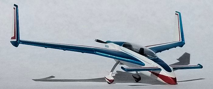 y rocked a bit fore and aft, so I applied epoxy
to the back edge and set the model aside to move onto the main landing gear.
y rocked a bit fore and aft, so I applied epoxy
to the back edge and set the model aside to move onto the main landing gear.
I didn’t trust the resin legs to stay in one piece, so I used some 1/8th inch by 1/32nd inch brass strip stock instead. I bent a couple of pieces to the mimic the curve and used a grinding bit in a rotary tool to taper the ends and give them some semblance of an airfoil shape. The legs were finished up with 320 grit sandpaper, trimmed to length, sprayed with some rattle can primer and glued into place. Those joints were cleaned up and then the wheels glued onto the ends and their joints cleaned up.
I went back to the canopy and applied a thin bead of epoxy to the front and taped it down. The join was cleaned up with a swipe of a cotton swab soaked in rubbing alcohol. I let the sides float on the fuselage.
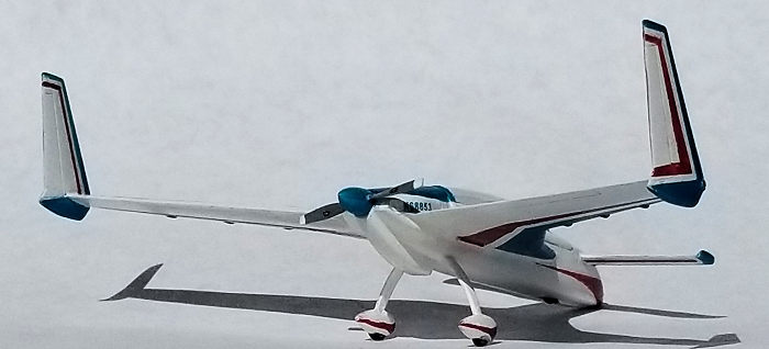
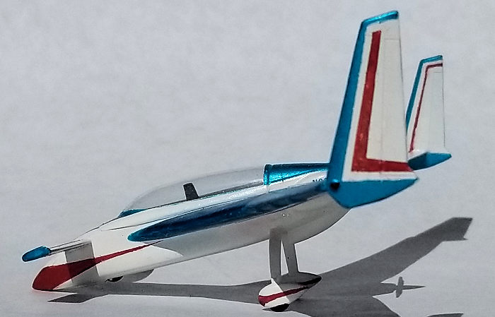
The nose wheel was cleaned up and glued into place in the retracted position. Long EZs sit on the tarmac with the nose wheel retracted so one can climb in or out of the cockpit. (I have no idea how the passenger can get in and out gracefully.) The last pieces to attach were the fin/rudder units and they went on without much fuss. After carefully cleaning up the prop -- the blades are very thin -- everything was given a coat of white primer. Touch ups were attended to, which is easier to say than to do. While the wing to fuselage seam was smooth, the primer revealed that it was high, so it was several sessions of filing, sanding, and priming to get everything level.
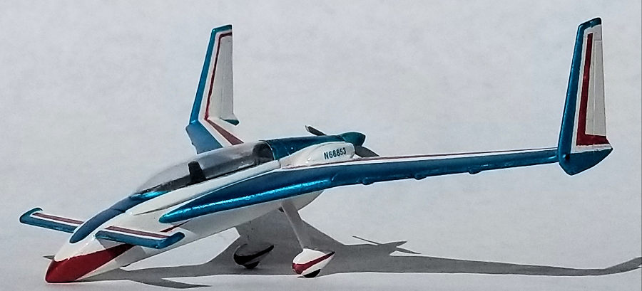
| COLORS & MARKINGS |
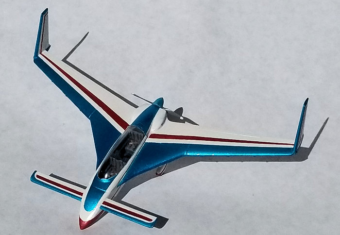 I created a
scheme that I thought would look nifty. Several light coats of gloss white
acrylic thinned with distilled water and rubbing alcohol plus a few drops of
airbrush flow enhancer where sprayed on the model. A light swipe with 1000 grit
wet/dry sandpaper, again, used wet was done between coats. Now the fun started
with the model receiving masks for the acrylic metallic blue. That paint was
thinned the same as the white. The next day the model was masked for the
metallic red trim. While applying those masks, I discovered that the blue did
not adhere very well and rubbed off in the places where I frequently handled the
model. The red paint was mixed the same as the other colors. When the masks for
the red were peeled off, I discovered that not only was the adhesion poor, but
there was also LOT of bleeding. I’m blaming the age of the tape I used. At least
I was able to scrape the excess paint back to the masked line, re-mask and paint
again. In some places I had to mask the colors and re-paint the white.
I created a
scheme that I thought would look nifty. Several light coats of gloss white
acrylic thinned with distilled water and rubbing alcohol plus a few drops of
airbrush flow enhancer where sprayed on the model. A light swipe with 1000 grit
wet/dry sandpaper, again, used wet was done between coats. Now the fun started
with the model receiving masks for the acrylic metallic blue. That paint was
thinned the same as the white. The next day the model was masked for the
metallic red trim. While applying those masks, I discovered that the blue did
not adhere very well and rubbed off in the places where I frequently handled the
model. The red paint was mixed the same as the other colors. When the masks for
the red were peeled off, I discovered that not only was the adhesion poor, but
there was also LOT of bleeding. I’m blaming the age of the tape I used. At least
I was able to scrape the excess paint back to the masked line, re-mask and paint
again. In some places I had to mask the colors and re-paint the white.
The prop hub was painted blue and the blades gray, with white tips. The wheels were painted rubber.
Rummaging through the decal dudgeon, I found a pair of ID numbers that are non-metallic blue, but close in hue, and a pair of small ovals that could pass for a propeller manufacturer’s logo. I think this is the fewest decals I’ve ever applied to a model.
After the decals dried, a clear gloss coat was sprayed on.
The last two steps were to unmask the canopy and glue on the prop.
| CONCLUSIONS |
This model assembled quickly – even with adding the cockpit details. After all of the handling during the masking process, I am glad that I used brass gear legs. The bulk of the time spent on the project was devoted to sanding, masking, painting, and re-painting. (I guess that is much like building the real thing.) About 24 hours were spent on this project.
I’m planning on entering this Long EZ in a contest where the closest category is “Aircraft 1/48th Allied Prop”. I’m curious to see how it will look sitting next to all of the heavily weathered spitcatboltcorhawkhurrilightstangs.
25 November 2019
Copyright ModelingMadness.com
If you would like your product reviewed fairly and fairly quickly, please contact the editor or see other details in the Note to Contributors.
Back to the Main Page Back to the Review Index Page Back to the Previews Index Page