| KIT #: | 72372 |
| PRICE: | $35.00 |
| DECALS: | Two options |
| REVIEWER: | John Summerford |
| NOTES: |
| HISTORY |
 The Cobalt Co50 Valkyrie is a single-engine, four to five-seat homebuilt
aircraft, arranged in a canard, pusher configuration. A light aircraft intended
for private ownership, it was initially developed by Cobalt Aircraft of San
Francisco, California, but the company ceased operations in July 2018 and the
design is now being developed by the Centauri Aircraft Company.
The Cobalt Co50 Valkyrie is a single-engine, four to five-seat homebuilt
aircraft, arranged in a canard, pusher configuration. A light aircraft intended
for private ownership, it was initially developed by Cobalt Aircraft of San
Francisco, California, but the company ceased operations in July 2018 and the
design is now being developed by the Centauri Aircraft Company.
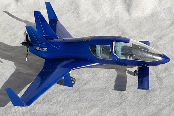
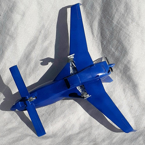
The composite design incorporates retractable landing gear, a pusher engine configuration, a canard, twin vertical stabilizers and automatic airbrakes. A ballistic parachute is provided as an option. Kit production is planned to be carried out in the United States.
As of 2020, two airframes have been certified.
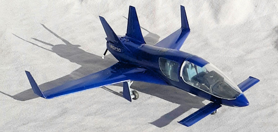
At a quick glance, the Valkyrie looks like an upsized Rutan VariEze with similar wing planform and canard. Wingspan of Valkyrie is 30 ft (9.1 m) versus the VariEze’s 22 ft 2.5 in (6.77 m). Seating capacity is five versus two respectively. I’m not sure, but I think the middle passenger will be squeezed by his seatmates.
| THE KIT |
A photo of Valkyrie parked on the tarmac and insert photos providing different views adorns the box lid. A yellow triangle in the lower left corner proclaims “Only 500pcs”. I thought that was referring to a jigsaw puzzle, but it has been suggested to me that it means that Amodel produced 500 copies. The instructions note that kit is based on "short-run technology and only for experienced modelers"
 Indeed, the four gray sprues look similar in style to those of a Dora Wings
kit. Some flash is present and detail is suitable for the scale. Interestingly,
the fuselage halves are clear and the canopy is a separate piece. It's hard to
see, but there are two windows on each side aft of the canopy for the rear seat
occupants. A small fret of photo-etch, vinyl masks, and decals complete the kit.
Total parts count is 96, including a six-piece boarding ladder.
Indeed, the four gray sprues look similar in style to those of a Dora Wings
kit. Some flash is present and detail is suitable for the scale. Interestingly,
the fuselage halves are clear and the canopy is a separate piece. It's hard to
see, but there are two windows on each side aft of the canopy for the rear seat
occupants. A small fret of photo-etch, vinyl masks, and decals complete the kit.
Total parts count is 96, including a six-piece boarding ladder.
Assembly starts with the cockpit and it, plus a rear bulkhead is trapped in the fuselage halves in step 4, The next six steps build the wings and mating them to the fuselage. Landing gear and prop sub-assemblies follow. In step 14, the instructions do not call attention to a choice that has to made. If one wishes to pose the canopy closed, the coming piece B1 should be glued in place as shown. Step 15 adds the underside bits, followed by step 16 that calls for adding the fins and closed canopy. The next four steps illustrate how to install the canopy open, again without highlighting this as an option.
A closed canopy would make painting much easier because masking an exposed cockpit is a challenge. Two options for paint schemes are printed on a separate sheet. Option one is a trendy gloss black plane with white or silver lettering and option two is aluminum paint with black lettering. Or, one could think of this as a blank canvas and do a “How about…” and let one’s imagination run wild.
| CONSTRUCTION |
Not passing up an opportunity to start somewhere other than the cockpit, the overhead passenger window part was tinted with Tamiya Smoke. It, and the side windows, were covered with the vinyl masks to protect them.
Assembling the cockpit started with painting the coaming and decaling the instrument panel, then gluing them together. In step 2, the rear bulkhead is supposed to added, but I waited until the rest of the cockpit was ready for installation. Parts B21 and B22, the side consoles that hold the joysticks, are handed and cross-labeled. Their outside faces are supposed to be plated with photo-etch pieces, but I didn’t see any reason for them. As it turned out, I needed to sand those faces down a bit to get a good fit in the fuselage.
 Because there are no locating pins or tabs, I spent over an hour test fitting
where and how the cockpit sub-assembly mounts to the fuselage. I taped the
halves together and inserted the cockpit from below and found that the rear
seats are too tall and sanded the headrests to fit. In order to determine how
far forward to mount the cockpit in the fuselage, I used the bottom
wing/fuselage piece as a guide. Knowing that, attention turned to the engine
bulkhead. Again, there are not locating points, so it was aligned with a panel
line.
Because there are no locating pins or tabs, I spent over an hour test fitting
where and how the cockpit sub-assembly mounts to the fuselage. I taped the
halves together and inserted the cockpit from below and found that the rear
seats are too tall and sanded the headrests to fit. In order to determine how
far forward to mount the cockpit in the fuselage, I used the bottom
wing/fuselage piece as a guide. Knowing that, attention turned to the engine
bulkhead. Again, there are not locating points, so it was aligned with a panel
line.
Bringing cockpit, bulkhead and fuselage pieces together was a challenge. After double checking that the tape ensured full contact, the cockpit was inserted, but allowed to float. A drop of liquid cement was flowed into the upper fuselage seam at the rear. When that had cured sufficiently, the cockpit was maneuvered into place and a couple of drops tacked it securely and hand pressure kept it from moving. Unfortunately, I managed to mar the inside of one window with glue. (Crap.) The rear bulkhead was aligned with the panel line and glued in place, again using hand pressure until the glue cured.
The wings came next and all the seams needed filler. Before they were mated to the fuselage, the top window in the fuselage was installed. It was slightly oversized, so the edges were chamfered and it didn’t fall inside when it was glued in place.
Checking the fit of wings to the fuselage, I noticed that I guessed right on the placement of the engine bulkhead, since it fell into the trough molded in the interior of the bottom wing. Part B10, which is a plate for mounting the canopy opened, is illustrated as attaching under the cockpit floor, extending forward. There are not locating tabs for this piece and it contradicts with the earlier cockpit placement illustration. I’m glad I let this portion of the cockpit float. I decided to install the piece from underneath after the wings were attached
As expected, the seams needed filling. Before getting to that operation, the canopy mount, engine compartment top panel and rear face were added. The canopy frame was glued to fuselage. The canopy was masked and the test fit revealed that the front seats were also too tall and their headrests were sanded down. The front of the canopy also needed some trimming. After the canopy was glued in place, the seams were addressed.
Tail feathers, winglets, and canard were glued in place and their seams attended to before applying paint.
| COLORS & MARKINGS |
 A wipe down of alcohol with a lint free cloth prepared the model for a coat
of Alclad II Gray primer. More work on the seams followed, especially in the
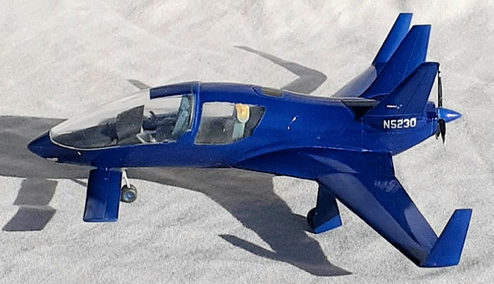
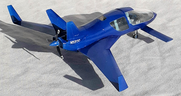
wing to fuselage area. This being a Cobalt design, the model was sprayed with a
couple of coats of Alclad’s Candy Cobalt Blue. The silver-colored ID number and
logo decals were applied onto the cowl and fins respectfully. They behaved well.
A gloss top-coat was sprayed on to protect the decals.
A wipe down of alcohol with a lint free cloth prepared the model for a coat
of Alclad II Gray primer. More work on the seams followed, especially in the
wing to fuselage area. This being a Cobalt design, the model was sprayed with a
couple of coats of Alclad’s Candy Cobalt Blue. The silver-colored ID number and
logo decals were applied onto the cowl and fins respectfully. They behaved well.
A gloss top-coat was sprayed on to protect the decals.
When the masks were pulled off, I was disappointed to see bits of sanding debris stuck to the inside of the canopy by static electricity, even though I sanded the headrests with the model upside down. (Another Crap) I guess I should have cranked up the pressure on my airbrush’s regulator and blown the compartment thoroughly instead of using my lungs.
Assembling the landing gear is straight forward and some patience is required gluing it in place. Adding the prop was the final step.
| CONCLUSIONS |
What a nifty anime/sci-fi looking plane! Since this aircraft is unusually shaped, and the kit is a short-run production, the handling of the build sequence is also unusual. The instructions could be clearer, especially in the cockpit area. At around 17 hours spent on this project, I recommend that modelers have experience with short-run kits before tackling this one.
15 August 2022
Copyright ModelingMadness.com. All rights reserved. No reproduction in part or in whole without express permission.
If you would like your product reviewed fairly and fairly quickly, please contact the editor or see other details in the Note to Contributors.