Valom 1/48 BN-2 Islander
| KIT #: | 48010 |
| PRICE: | $75.00 |
| DECALS: | Two options |
| REVIEWER: | John Summerford |
| NOTES: |
| HISTORY |
 The Britten-Norman BN-2 Islander is a British
light utility aircraft and regional airliner that has been in production for
more than 55 years. It was developed in 1963 as a simple and inexpensive twin
piston engine aircraft that favors payload over range and cruising speed, making
suitable for short haul operations. Over 1400 of all types have been built.
The Britten-Norman BN-2 Islander is a British
light utility aircraft and regional airliner that has been in production for
more than 55 years. It was developed in 1963 as a simple and inexpensive twin
piston engine aircraft that favors payload over range and cruising speed, making
suitable for short haul operations. Over 1400 of all types have been built.
On 13 June, 1965 the first prototype BN-2 Islander conducted its maiden flight, powered by a pair of Rolls-Royce/Continental IO-360B piston engines. These were later replaced by more powerful Lycoming O-540-E engines, which were located further outboard on the wings for superior single-engine climb performance. 24 April, 1967 saw the first flight of a production Islander. Type certification was received from the UK in August 1967, and by US authorities in December of the same year.
Various cabin configurations and equipment load outs are available to suit a wide variety of different purposes, including charter flights, scheduled flights, agricultural uses, aerial firefighting, air freight, VIP/executive transport, aerial surveillance, air ambulance, paradropping and law enforcement.
| THE KIT |
A single bag holds all of the parts. Three light tan plastic sprues make up the airframe with a separate bag holding the clear sprue and another bag holding the decals and photo-etch fret. Some flash is present and the depth of the panel lines, if present, is inconsistent.
 Of note are two sets of engine cowls. The
difference between the cowls is the length of the air scoop. No mention of the
short-scoop version is mentioned in the instructions. I think the long-scoop
version is for a carbureted engine and the short-scoop is for the fuel-injected
engine of the -2A. Looking at photos on the internet, the airliners have the
long-scoop.
Of note are two sets of engine cowls. The
difference between the cowls is the length of the air scoop. No mention of the
short-scoop version is mentioned in the instructions. I think the long-scoop
version is for a carbureted engine and the short-scoop is for the fuel-injected
engine of the -2A. Looking at photos on the internet, the airliners have the
long-scoop.
Also of note are 26 photo-etch parts that represent panels to be glued to the underside of the fuselage. My first thought was to wonder why this detail was not molded into the plastic. Perhaps much of this detail would be lost when cleaning up the fuselage seam. Total parts count, including photo-etch and an acetate film of instrument faces, is 152.
Assembly instructions are printed on two sheets of folded A-4 paper, creating eight pages. The parts map is on two of the pages and the assembly is broken down into ten steps. Step 4 indicates ballast in the nose, but doesn’t specify how much. A separate history in Czech and English, plus a painting and decaling guide in color is included. 21 different colors are cited and they are crossed referenced to Humbrol, Agama, Model Master, and Gunze Sangyo paints plus F.S. codes
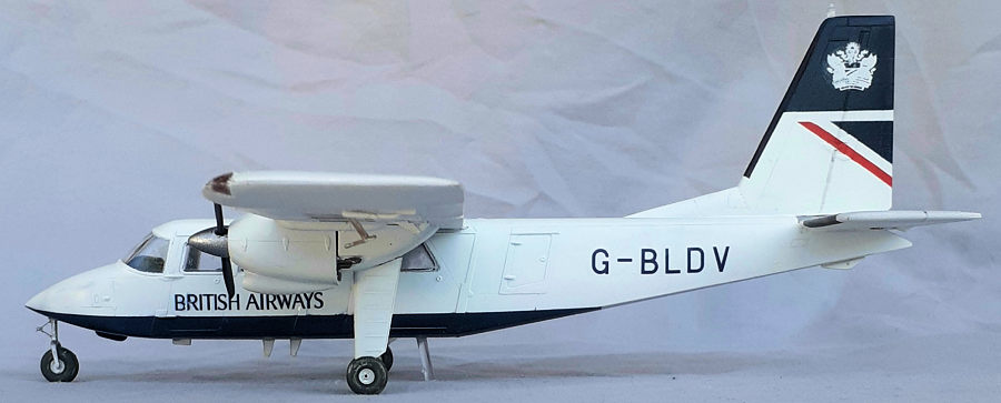
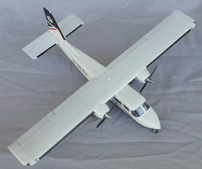
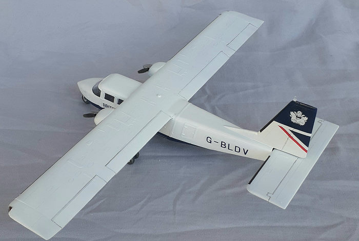
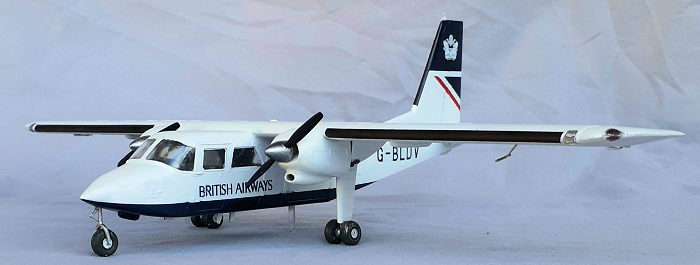
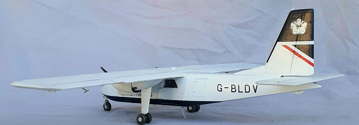
This kit provides two airliner options, Logan Air of Scotland, (G-BOMG) or British Airways. G-BLDV) Both paint schemes are white over a dark blue named “Oxford Blue” on the fuselage underside. Oxford blue is darker than insignia blue. The British Airways scheme includes the blue paint on the upper half of the vertical tail with a white crown decal. Decals are provided for a scrap section of the Union Jack below the blue field, but matching the blue of the decal to the paint will be a challenge. It might be easier to paint the entire tail and then apply the crown decal.
| CONSTRUCTION |
Step 1 calls for building up the instrument panel with the nicely detailed photo-etch and instrument faces film. I wondered how much of that detail would be viewable, so I removed the fuselage halves from the sprue, cleaned up the mold gates plus seams and trapped the coaming between the halves. I concluded that if the windshield was ultra-thin, the panel might be viewable. Given that, I didn’t bother with the instrument faces, or the center console with the throttle levers. Instead, I epoxied the instrument panel to the backing, trimmed it, glued the yokes in place and painted it all black. When that was dry, a white artist’s pencil was swiped over the panel and everything given a dusting of light sand pigment powder. Good enough.
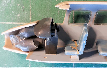 I deviated from the instructions and continued
with the interior instead of assembling the cowls and landing gear. I skipped
adding the photo-etch seatbelts to the passenger seats as well as the rudder
pedals. Lead ballast was packed into the right fuselage half forward of the
instrument panel. This left room for more if needed. The windows were glued in
place from the insides and the fuselage halves mated. As suspected, cleaning up
the seam on the underside obliterated all of the detail.
I deviated from the instructions and continued
with the interior instead of assembling the cowls and landing gear. I skipped
adding the photo-etch seatbelts to the passenger seats as well as the rudder
pedals. Lead ballast was packed into the right fuselage half forward of the
instrument panel. This left room for more if needed. The windows were glued in
place from the insides and the fuselage halves mated. As suspected, cleaning up
the seam on the underside obliterated all of the detail.
The windscreen was glued in place from the outside and the fit needed work. Finger pressure was needed to hold it in place while the glue set. Filler was thinned and carefully brushed around the entire edge. Sections of the windshield were shielded with tape and more filler applied as needed and sanded to blend it all together. With that done, all of the clear parts were masked to protect them during the rest of the build.
Reverting to step 2, the cowls were assembled, and more filler was slathered in the seams and smooth over.
Step 6 combines all the major components, first by gluing the wing together. There are two different types of wing tips to cap the ends. The correct ones are misnumbered. Part number 13 is not numbered at all and should be mated to mated to part 12 for the right tip. while parts 11 and 14 comprise the left tip. In addition to the navigation lights, clear landing light lenses at the tips are called for. These were painted chrome on the inside before gluing in place. A couple of scoops on the underside near the engines are installed in step 8 but were added at this time.
 The stabilizer/elevators, like the wings, are
molded as upper and lower halves. Getting that assembly to slot into place
required removal of material from the fuselage to get a good fit. This was also
the case when mating the wings to the fuselage. The underside of the wing is the
cabin roof, so it fits over an opening in the fuselage. In order to keep debris
out of the cabin, bits of foam rubber were temporally packed into the cabin. A
clamp held the two assemblies in place while the glue cured. The seam at the
trailing edge of the wing and fuselage was filled and sanded.
The stabilizer/elevators, like the wings, are
molded as upper and lower halves. Getting that assembly to slot into place
required removal of material from the fuselage to get a good fit. This was also
the case when mating the wings to the fuselage. The underside of the wing is the
cabin roof, so it fits over an opening in the fuselage. In order to keep debris
out of the cabin, bits of foam rubber were temporally packed into the cabin. A
clamp held the two assemblies in place while the glue cured. The seam at the
trailing edge of the wing and fuselage was filled and sanded.
There are no markings or structure on the wings to locate the cowls, but there are for the fairings that hold the main landing gear legs. Those were glued in place first, then the cowls. A check to see if the model was still a tail-sitter revealed that an equivalent amount of lead needed to be added to the nose before the cone could be glued in place. The lead was secured in place with epoxy to avoid cyano fumes fogging the windshield. Returning to the cowls, their gaps along the leading edge of the wing were filled and a cotton swab soaked in lacquer thinner wiped away the excess, leaving clean, neat seam.
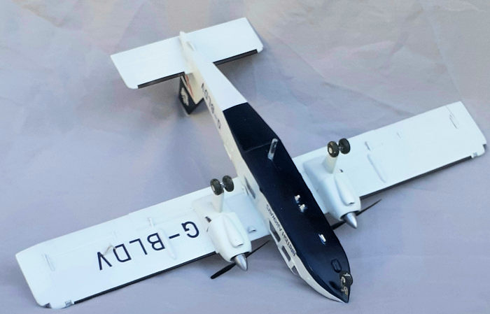
The main gear legs were added, then one more bit of lead was added to the nose cone before it was glued in place. Flap and aileron actuators were glued to the underside of the wing, followed by blade antennas on the fuselage bottom. I decided to skip the tedious task of adding the photo-etch detail on the underside, since it would not be seen, particularly with the color scheme. The model was ready for paint.
| COLORS & MARKINGS |
 As per my usual technique, I sprayed rattle can
white automotive primer over everything, then worked some more on some seams and
put on another coat. Gloss acrylic white went over the primer, except on the
underside of the fuselage. The red stripe on the tail was masked and sprayed on.
When that cured, the tail was masked for the blue, along with the fuselage. I
don’t have any jars or tins of “Oxford Blue” laying around, so I added a touch
of MRP paint’s RLM 66 to Alclad II cobalt blue I got a very good color match.
The next day the colors and wings were masked and the rubber deicer boots
painted.
As per my usual technique, I sprayed rattle can
white automotive primer over everything, then worked some more on some seams and
put on another coat. Gloss acrylic white went over the primer, except on the
underside of the fuselage. The red stripe on the tail was masked and sprayed on.
When that cured, the tail was masked for the blue, along with the fuselage. I
don’t have any jars or tins of “Oxford Blue” laying around, so I added a touch
of MRP paint’s RLM 66 to Alclad II cobalt blue I got a very good color match.
The next day the colors and wings were masked and the rubber deicer boots
painted.
One piece of lead came loose and knocked about cabin, ruining the balance. I put off dealing with that until the end.
Applying the decals was simple, but they proved to be fragile and adhesion was poor. Most of the “D” in ID lettering on the right side peeled off and a bubble formed on the wing ID. The latter was given some diluted white glue and I cheated on the former by placing a “B” from the alternate scheme ID. I doubt anyone will notice.
| FINAL BITS |
 Getting the nose wheel assembly together was a
challenge with the scissors link being done in two photo-etch pieces. The main
wheels are under engineered with practically no mating surfaces for glue on the
hubs and axles. I didn’t bother with the single-piece photo-etch scissors links.
I’m not sure there is enough material to drill holes for pins, so all of the
joints were reinforced with epoxy.
Getting the nose wheel assembly together was a
challenge with the scissors link being done in two photo-etch pieces. The main
wheels are under engineered with practically no mating surfaces for glue on the
hubs and axles. I didn’t bother with the single-piece photo-etch scissors links.
I’m not sure there is enough material to drill holes for pins, so all of the
joints were reinforced with epoxy.
While the model was still on its back, the pitot was glued in place followed by the props and the model flipped over. I held my breath and set the model on the wheels and confirmed that it’s a tail sitter. After letting out a sigh, I flipped the model over again and drilled a hole for a clear piece of sprue. The model now rests on four points, which, if it were a car, would make me happy.
Like placing a cherry on top a sundae, the white navigation light was glued to the top of the fin and the build was complete.
| CONCLUSIONS |
Building this kit caused me to ponder how accurate the end result should be. For what you get, this kit is on the pricey side. Many parts were not used, some are called for a different version and others, mostly photo-etch, I declined add. A lot of filling and sanding was required. The decals in my kit were barely adequate and I’m glad I painted the fin and rudder. After spending about 25 hours on this build, I have a striking model.
October 2014
Copyright ModelingMadness.com. All rights reserved. No reproduction in part or in whole without express permission.
If you would like your product reviewed fairly and fairly quickly, please contact the editor or see other details in the Note to Contributors.