
MPM 1/72 Douglas DC-2
| KIT #: | 72515 |
| PRICE: | $30.00 |
| DECALS: | Four options |
| REVIEWER: | Torben Plesberg |
| NOTES: | Short run kit |
| HISTORY |
In the early thirties, the air transport in the USA was dominated by large uneconomical aircraft from Fokker, Ford and Curtiss. A single exception was the all metal smooth-skinned Boeing 247 exclusively in service with United Air Lines. The competing air lines wanted a similar aircraft, and in 1932 the vice-president of TWA invited five US aircraft manufacturers to design a plane, which could cope with the Boeing 247. Even if the specification asked for a three engine aircraft, the twin engine DC-1 from Douglas Aircraft could maintain the safe margin of a three engine aircraft, and the DC-1 was accepted by TWA.
The
construction of the prototype DC-1 was started early in 1933, and by July 1 it
took to the air powered by two 700 hp Pratt & Whitney Hornet radials. This
aircraft could carry 12 passengers, had a cruising speed of 315 km/h and a range
of 1700 km, all figures better than the Boein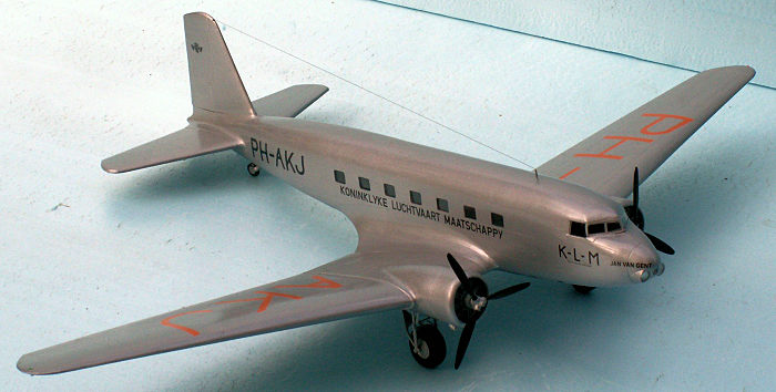 g 247. The DC-1 was delivered to
TWA in September 1933. In February 1934 it set a new US transcontinental speed
record between LA and Newark. And this was only the first of 11 US and 8 world
speed and distance records, which were set up in the following months.
g 247. The DC-1 was delivered to
TWA in September 1933. In February 1934 it set a new US transcontinental speed
record between LA and Newark. And this was only the first of 11 US and 8 world
speed and distance records, which were set up in the following months.
This aircraft design could be stretched further for 2 more passengers and with more powerful engines and increased weight of baggage and freight, the new aircraft was designated DC-2. Other differences from the DC-1 were an enlarged rudder and provision for wheel brakes. TWA ordered 24 of the DC-2.
The fate of the DC-1: It was sold to Howard Hughes, who later sold it to Viscount Forbes in England in May 1938. In November, it was sold to a Spanish Airline – LAPE. After the civil war, the DC-1 came to Iberia, and serving with this airline, the DC-1 crashed on a flight from Malaga in 1940.
Donald Douglas’s DC-2 became a hit and 198 planes were produced and entered service with American Airlines (18), Eastern Airlines (10), Pan American (10), KLM (19) + many smaller airlines. The USAAC got 57 DC-2 and 5 for the US Navy.
However, the DC-2 was developed further: 78 cm longer, wing span 3 m greater, the fuselage deeper by 7.6 cm and most important: 66 cm wider, which allowed a third row of passenger seats. The DC-3 was born and this airliner became a mega hit among airlines for many years to come.
| THE KIT |
 The kit
comes in a nice box with two of the options on the lid: A Luftwaffe DC-2 and an
all- orange colored DC-2 of KLM. The box is top opened and suitable as a base
for the construction. There are three sprues in a medium grey styrene and a
clear one with the transparent parts. The instructions is an A5 booklet of 10
pages. Page one is a short history of the DC-2 in four languages. Page two and
three show the sprues with numbered parts. The seven steps of construction are
shown on pages three to six. The last four pages show the color schemes and
decaling of the four options of the kit: Three KLM aircraft and a Luftwaffe
aircraft, being the personal transport of General der Flieger Christensen. There
are no less than four decal sheets, two large and comprehensive ones, and two
smaller ones. The quality is first class, everything in register and a well-
functioning carrier film. It is a short run kit, and not all parts fit properly
together.
The kit
comes in a nice box with two of the options on the lid: A Luftwaffe DC-2 and an
all- orange colored DC-2 of KLM. The box is top opened and suitable as a base
for the construction. There are three sprues in a medium grey styrene and a
clear one with the transparent parts. The instructions is an A5 booklet of 10
pages. Page one is a short history of the DC-2 in four languages. Page two and
three show the sprues with numbered parts. The seven steps of construction are
shown on pages three to six. The last four pages show the color schemes and
decaling of the four options of the kit: Three KLM aircraft and a Luftwaffe
aircraft, being the personal transport of General der Flieger Christensen. There
are no less than four decal sheets, two large and comprehensive ones, and two
smaller ones. The quality is first class, everything in register and a well-
functioning carrier film. It is a short run kit, and not all parts fit properly
together.
| CONSTRUCTION |
If you follow the instructions, you will end up with an accurate 1/72 scale replica of a DC-2. I shall in the following give my comments to the seven steps of construction:
Step one: Since it is impossible to see the interior on a finished model, I simply dropped step one – waste of time!
 Step
two: The windows fit rather precisely into the openings of the fuselage halves.
However, it is advisable to sand a horizontal and a vertical side of each window
using a fine grained sanding stick. Otherwise, the fit will be too narrow, and
difficult to press the windows in place. No glue is needed, only a layer of
clear gloss varnish on the inner sides, when all windows are correctly in place.
The large side window of the cockpit, parts 19, does only fit in the starboard
side. The port side needs a small cut at the nose, since the recess is not long
enough.
Step
two: The windows fit rather precisely into the openings of the fuselage halves.
However, it is advisable to sand a horizontal and a vertical side of each window
using a fine grained sanding stick. Otherwise, the fit will be too narrow, and
difficult to press the windows in place. No glue is needed, only a layer of
clear gloss varnish on the inner sides, when all windows are correctly in place.
The large side window of the cockpit, parts 19, does only fit in the starboard
side. The port side needs a small cut at the nose, since the recess is not long
enough.
Step three: In the port fuselage half, a 2.5 mm gauge hole must be drilled in the door to the rear for the circular window, part 44. If you have done step one, it is time to place the interior parts now, and paint them according to the instructions. The fuselage parts can now be glued together. Be careful: there are no assembly pins and holes to secure a correct assembly. Tape is very useful to get the halves in alignment.
Step four causes no problems. Good that the tail planes and the fin are not curving inside. This makes the assembly a lot easier. However, they need some clamps to avoid cracks in the edges.
Step
five: As with the fuselage there are no pins and holes in the wing halves, and
these must be very carefully glued together. Next the central underwing is glued
in place. When set, the assembled wings are glued in place. A couple of wedges
are placed under the wing tips to secure a correct dihedral – 7 degrees as shown
on the sketch. Finally the
 tail planes are glued in place – no dihedral or anhedral!
Step six: Many of the smaller parts have a bad fit and need some trimming. Especially the nose needs some care. The front of the assembled fuselage is bigger than the nose, part 26, and must be sanded down to fit properly to the nose. The landing lights are too protruding and must be reduced. A couple of discs of metal foil were punched and put into the openings of the landing lights to simulate parabolic reflectors.
Step seven: It is too bad to have to glue three propeller blades to a hub! It is not an easy operation, and a jig is necessary if the result shall be acceptable. The propellers should have been two complete units. I made a couple of 2 mm shafts for the propellers to rotate – and stop rings 3.6 mm gauge and only 1.5 mm thick. With these + some milling of the engine and the cowling, I succeeded in making the propellers movable. Unfortunately, I did not have suitable propellers in my stocks. It would have been much easier.
The transparent parts for the landing lights are far too thick. I punched some thinner ones from thin acetate packing material, and glued these in place with clear gloss varnish.
The tail fin has a bad fit to fuselage and ditto the tail planes – sanding necessary.
The central wing has a bad fit to the fuselage on the upper side – especially to the rear. A lot of sanding and filling is necessary to attain a smooth fit.
The windscreen was glued in place with clear gloss varnish, and when set, the cracks were tightened with white glue. This glue for wood is a “magic healer” of all sorts of smaller cracks! True wonders can be made using white glue and a finger to apply the stuff smoothly.
| COLORS & MARKINGS |
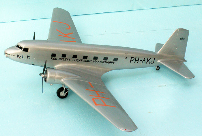
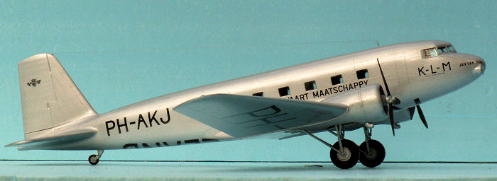
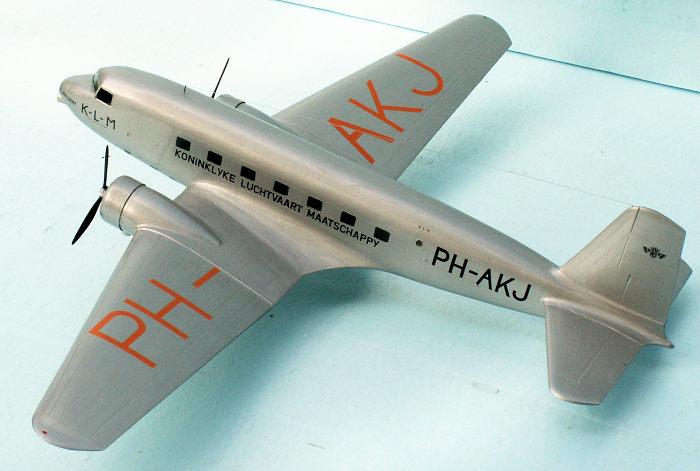
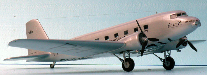 I choose
to paint and decal my model as “Jan van Gent”, PH-AKJ of the Royal Dutch Airline
KLM as it looked in 1935. The color scheme is aluminum all over, HB 56 or 27001.
Tires and propeller blades are matt black, HB 33. The wheel wells are Zink-
chromate, Revell 360. The model got two layers of HB Gloss Cote clear varnish to
facilitate the decaling and avoid silvering. Jan van Gent was the fourth son of
King Edward III and he got the title “Duke of Lancaster” in 1362.
I choose
to paint and decal my model as “Jan van Gent”, PH-AKJ of the Royal Dutch Airline
KLM as it looked in 1935. The color scheme is aluminum all over, HB 56 or 27001.
Tires and propeller blades are matt black, HB 33. The wheel wells are Zink-
chromate, Revell 360. The model got two layers of HB Gloss Cote clear varnish to
facilitate the decaling and avoid silvering. Jan van Gent was the fourth son of
King Edward III and he got the title “Duke of Lancaster” in 1362.
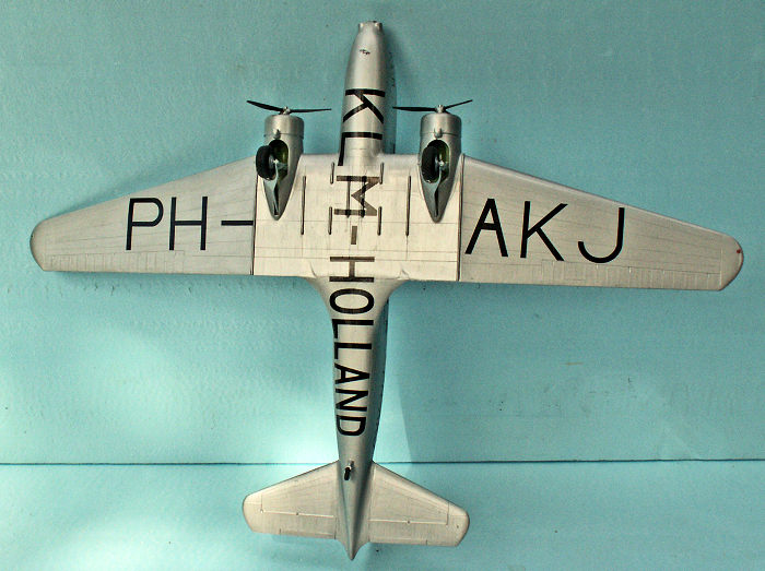
Some of the decals are rather large, especial the registration letters, which are orange on the upper sides of the wings, and black on the undersides. On the underside of the fuselage there is a very large decal: KLM HOLLAND, stretching from the propellers to the tail wheel. It is always important to handle large decals with the utmost care. I found it a good idea to separate the large underside decal in two parts. This makes the applying of the decal much easier – and safer. The quality of the decals is first class, and the carrier film is strong enough to avoid cracking.
| FINAL CONSTRUCTION |
 The last
item to finish the completed DC-2 was the antenna – not with the kit. A 0.1 mm
gauge nylon wire is recommended for the antenna. Further two pieces of 0.5 mm
gauge brass tubing, 10 mm and 5 mm long, are needed to fasten the wire. The
inner gauge of the tubes is 0.3 mm, and this is sufficient to allow the antenna
going through. A single knot in the end of the wire will fasten it in the tubes.
Now, the art is to make the two knots in exactly the right places. The length of
the wire should be a couple of mm shorter, than the distance between the tubes.
This secures the wire to be ruler straight. The 0.5 mm holes for the tubes must
be drilled before the length of the wire can be known. I always start with the
rear hole, close to the top of the fin. The 5 mm tube with the knot in the end
is pressed into the hole – no glue necessary. Now the hole for the front wire
tube can be drilled, and the 10 mm tube with the knot in the end is pressed half
through the hole. Be careful when handling the model with the antenna in place.
It is almost invisible, however don’t forget that it is there!
The last
item to finish the completed DC-2 was the antenna – not with the kit. A 0.1 mm
gauge nylon wire is recommended for the antenna. Further two pieces of 0.5 mm
gauge brass tubing, 10 mm and 5 mm long, are needed to fasten the wire. The
inner gauge of the tubes is 0.3 mm, and this is sufficient to allow the antenna
going through. A single knot in the end of the wire will fasten it in the tubes.
Now, the art is to make the two knots in exactly the right places. The length of
the wire should be a couple of mm shorter, than the distance between the tubes.
This secures the wire to be ruler straight. The 0.5 mm holes for the tubes must
be drilled before the length of the wire can be known. I always start with the
rear hole, close to the top of the fin. The 5 mm tube with the knot in the end
is pressed into the hole – no glue necessary. Now the hole for the front wire
tube can be drilled, and the 10 mm tube with the knot in the end is pressed half
through the hole. Be careful when handling the model with the antenna in place.
It is almost invisible, however don’t forget that it is there!
| CONCLUSIONS |
I have been looking for a DC-2 kit for many years. The MPM kit was therefore most welcome. It is not a perfect kit. As a short run kit it is not for beginners, however the kit is recommended for any experienced modeler who wants to make a model of the classic DC-2, the forerunner of the famous and numerous DC-3. Luftwaffe fans get an option for the personal transport plane of General der Flieger Friedrich Christiansen. During WWI, Christiansen was an ace with 21 kills and decorated with the Blue Max, and during WWII, he was as a Lieutenant-General and the Supreme Commander of the Wehrmacht in the Netherlands.
| REFERENCES |
Wikipedia: Article on “Douglas DC-2”. Article on Friedrich Christiansen, General in the Luftwaffe.
17 December 2020
Copyright ModelingMadness.com If you would like your product reviewed fairly and fairly quickly, please
contact
the editor or see other details in the
Note to
Contributors. Back to the Main Page
Back to the Review
Index Page
Back to the Previews Index Page