| KIT #: | SVM-72005 |
| PRICE: | $40.00 |
| DECALS: | One option |
| REVIEWER: | John Summerford |
| NOTES: | Short run |
| HISTORY |
The Beechcraft 1900 evolved from the Super King Air, featuring turboprop engines and could carry 19 passengers. The C model featured “wet-wing” fuel tanks that increased capacity from earlier bladder type and therefore increased the operating range. The engines were also upgraded to PT6A-65B engines, each shaft rated at 1,100 shaft horsepower (820 kW). The main visual difference from earlier models is the substitution of a cargo door for a passenger door at the aft section of the cabin. Production of all types ran from 1985 through 2002 with 695 rolling off the assembly line.
| THE KIT |
 A single
zip top bag holds six soft styrene gray sprues, one clear sprue, decals, and
another small bag holding a fret of 12 photo-etch parts. On this example,
surface flaws were found on underside of the fuselage halves and incomplete
panels lines in various places. Flash was also present on several sprues. Total
plastic parts came to 102.
A single
zip top bag holds six soft styrene gray sprues, one clear sprue, decals, and
another small bag holding a fret of 12 photo-etch parts. On this example,
surface flaws were found on underside of the fuselage halves and incomplete
panels lines in various places. Flash was also present on several sprues. Total
plastic parts came to 102.
Six pages comprise the instructions. The first page has a brief history and explanation of symbols. Page two has the parts map and assembly illustrations start at the cockpit and are on the last four pages. Once the Cockpit sub-assembly is complete, the wings come together, then the fuselage is assembled. Cabin detail, which would be difficult to view through the windows, is not present. The engine nacelles come next, are added to the wings, and that sub-assembly is mated to the fuselage, followed by the tail pieces. That leaves the landing gear, antennae, and photo-etch pieces to complete the model.
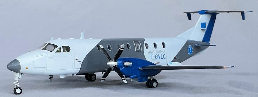
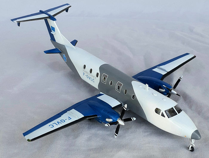
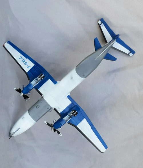
Printed in color, a separate sheet has the painting and decaling charts. The single option supplied is aircraft F-GVLC as seen operating out of Toulouse, France, Circa 2011
| CONSTRUCTION |
After examining the amount of flash on the sprues, the fuselage halves and wings were cleaned up, taped together and test fit. That join was then cleaned. The same was done with the windscreen to avoid cleaning the opening with the cockpit in place. Panel lines were scribed where needed.
Before starting the cockpit, the cabin windows were
glued in place. The openings for the windows needed to be enlarged slightly,
which made for a nice, tight fit. The instructions call for the wind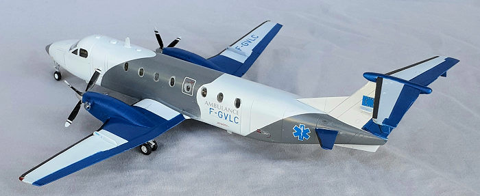 ows
to be installed from the outside, but by placing the fuselage half on a hard
surface with the inside up, the pieces could be pressed into place flush with
the outer surface. Extra thin liquid cement was wicked into the seams then the
windows masked.
ows
to be installed from the outside, but by placing the fuselage half on a hard
surface with the inside up, the pieces could be pressed into place flush with
the outer surface. Extra thin liquid cement was wicked into the seams then the
windows masked.
A good portion of an afternoon was spent assembling the cockpit’s 27 pieces. (Including waiting for the instrument panel decal dry.) More pieces could have been used, but I skipped the rudder pedals and used a single piece of styrene strip with a notch in it glued across the console to represent the throttle levers.
While waiting at various times for glue to cure for cockpit pieces, the wings were assembled, since they were still taped together from the test fitting.
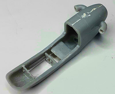
The roof of the nose gear bay was installed into the right fuselage half followed by the assembled cockpit. The instructions give a very helpful note to add 5g of weight in the nose. I added 7g just to be sure. That done, the fuselage was closed up. The earlier work spent cleaning the cockpit opening paid off when the windshield piece went into place with some gentle pressure, glued and masked. Tidying up the seams was relatively quick and the wings were offered up to the fuselage. Again, the earlier work cleaning up this area paid off with an easier effort in blending the join.
 Assembling
the nacelles was straight forward once the parts were cleaned up. The
instructions don’t reference it, but, due to the dihedral of the wings, the
nacelles are handed. I stumbled onto that bit of knowledge when I did a test fit
of one nacelle, and before starting the other, noticed “L”s molded into the
inner surfaces of one pair of halves and “R”s in the other pair. Sova-M missed a
detail on the propellers. When the engines shut down, the props automatically
shift to the feathered position. These are molded in the powered position, so
the props were cut across the hub and twisted into the correct position to glue
to the spinners and back plates.
Assembling
the nacelles was straight forward once the parts were cleaned up. The
instructions don’t reference it, but, due to the dihedral of the wings, the
nacelles are handed. I stumbled onto that bit of knowledge when I did a test fit
of one nacelle, and before starting the other, noticed “L”s molded into the
inner surfaces of one pair of halves and “R”s in the other pair. Sova-M missed a
detail on the propellers. When the engines shut down, the props automatically
shift to the feathered position. These are molded in the powered position, so
the props were cut across the hub and twisted into the correct position to glue
to the spinners and back plates.
There are multiple tail surfaces on this aircraft, so it takes longer than usual to get the tail assembled. Again, it was a straight forward process. But I did knock three of the four mini fins loose when masking and unmasking. With some trepidation, the multiple fin antennae were also glued in place, and only a couple were knocked off.
A couple of sessions of seam clean-up came next, then primer coats and more seam clean-up.
| COLORS & MARKINGS |
 After
painting everything white, masking for the curves of the gray areas was a
challenge to get them symmetrical. Drafting dividers and templates were the
tools needed. Masking for the blue surfaces was tricky due to the small jogs
between the flaps and the ailerons and the wing fences. After all that,
masking for the deicer boots was easy. A gloss coat was sprayed on to
prepare for decaling.
After
painting everything white, masking for the curves of the gray areas was a
challenge to get them symmetrical. Drafting dividers and templates were the
tools needed. Masking for the blue surfaces was tricky due to the small jogs
between the flaps and the ailerons and the wing fences. After all that,
masking for the deicer boots was easy. A gloss coat was sprayed on to
prepare for decaling.
The decals proved to be temperamental. They are very thin and required gentle handling. The frames around the emergency exit windows were cut into two to help tease them into place. There are supposed to be decals on each side the nose, but on one side, it folded under itself and on the other it tore into several pieces. Those pieces were wiped off and the other decal was painted over before unmasking. There are supposed to be markings surrounding the doors, but the decal for the front door also tore, so, it too, was wiped off and no attempt was made for the rear door. Another gloss coat was applied to seal the decals.
After unmasking, there were just a couple of touch-ups needed and these were done with a brush. Landing gear assembly and installation was easy. The tiny hinges for the doors were omitted because they more for decoration than structure. The final step was to bore the holes for the stubs of the spinner backplates with the next larger sized drill bit to attach the props.
| CONCLUSIONS |
For a short-run kit, this actually assembles easily after the parts clean-up. Some of the tiny detail pieces can be omitted without any concern. The decals are the weakest part and perhaps applying a coat of decal fix before wetting them is merited. Between the complex paint scheme, and the slow assembly process, nearly 30 hours was spent this project.
27 September 2022
Copyright ModelingMadness.com. All rights reserved. No reproduction in part or in whole without express permission.
If you would like your product reviewed fairly and quickly, please contact the editor or see other details in the Note to Contributors.