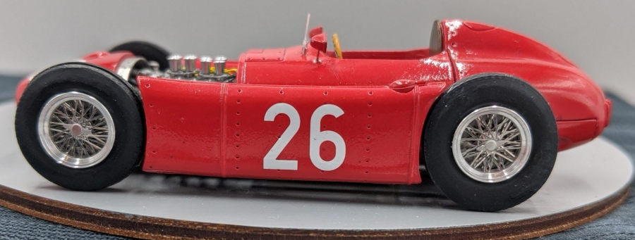
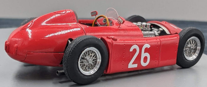
Model Factory Hiro 1/43 Lancia D-50
|
KIT #: |
K-395 |
|
PRICE: |
13,000 yen
|
|
DECALS: |
Three options |
|
REVIEWER: |
Rob Hart |
|
NOTES: |
Exquisite detail, high parts count,
interesting subject, very limited production |
Lancia & C. Fabbrica Automobili was founded on
27 November 1906 in Turin by Fiat racing drivers, Vincenzo Lancia
(1881-1937) and his friend, Claudio Fogolin (1872-1945). Lancia quickly
became known for it's engineering excellence. By 1950 Vincenzo's son, Gianni
was in charge and he felt the company would benefit from a strong showing in
competition. To that end, staff engineer Vittorio Jano designed
spectacularly successful racing versions of his Aurelia coupe and a series
of sports-racers for the 1953 World Sports Car Championship with an assault
on F1 to follow.
 Jano's F1 design, the D50, had a 2.5 litre DOHC V-8 that was angled in the
chassis to allow a lower overall height and let the drive shaft run at an
angle through the cockpit to a 5 speed transmission mounted directly to the
rear axle. The engine was rated at 260 BHP and at only 620 kilograms the car
would be the among the lightest F1 cars of its time.
Jano's F1 design, the D50, had a 2.5 litre DOHC V-8 that was angled in the
chassis to allow a lower overall height and let the drive shaft run at an
angle through the cockpit to a 5 speed transmission mounted directly to the
rear axle. The engine was rated at 260 BHP and at only 620 kilograms the car
would be the among the lightest F1 cars of its time.
Significantly, for the first time in F1, the engine was a stressed member of
the space frame. This made for more centralized mass and a lower weight. The
car also featured innovative sponsons between the wheels containing the fuel
tanks. Carrying the fuel load on both sides of the car instead of in one
large fairing at the rear enabled a better balance to be maintained as the
fuel burned off with less deterioration in handling over the course of the
race.
The front suspension was by a transverse leaf spring and upper and lower
wishbones with the upper wishbones having rocker arm suspensions operating
on inboard shock absorbers. Another transverse leaf spring suspended the
rear axle.
Lancia was able to obtain the services of one of the greatest F1 drivers of
the day, Alberto Ascari and he brought his close friend and mentor, Luigi
Villoresi along to the team. Lancia was able to provide two D50s for the
last race of 1954, the Spanish Grand Prix. Ascari put his car on the pole
and he led the race from the third lap. Unfortunately, neither car finished
the race with Villoresi dropping out on the first lap and Ascari retiring
eight laps later. It had not been a great start for the team, but it was a
promising one.
For 1955, a promising new driver, Eugenio Castellotti, joined the team in
time for the first race of the season, the Argentine GP. Ascari qualified
third and led 10 laps before crashing out of the race. His two team-mates
did not finish either. Ascari would win two minor non-championship races in
Turin and Naples respectively with his team-mates racking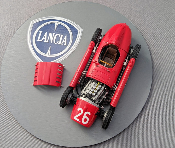 up top five
finishes in the same two races. For the first European World Championship
event, the Monaco GP, Ascari started in the middle of the front row between
the Mercedes W196s of Juan Manuel Fangio and Stirling Moss. At just before
half the race's distance, Fangio dropped out with Moss in the lead over
Ascari by a minute. On lap 80 Moss' engine blew up, but before he could
actually pass Moss on the track, Ascari overshot a chicane, went through a
guardrail, and plunged into the harbor. Ascari survived the dunking only to
be killed 4 days later while testing a Ferrari sports car. Without Ascari as
the lead driver, Lancia's F1 fortunes began to Falter. Lancia entered one
car for Castellotti in the Belgian GP. Castellotti took the pole and was
running third when the transmission failed. By this time Lancia's
competition program had pushed the company to the brink of bankruptcy. While
accountants attempted to sort out the firm's finances, the Lancia family
sold all of their shares to a group of industrialist investors. Enzo Ferrari
sensed an opportunity and, crying poor, declared that defending Italy's
honor and reputation in Grand Prix racing was ruining him financially. His
ploy worked and the new owners of Lancia passed over six D50s, all the
spares and castings, the transporters, and the services of engineer Jano.
Ferrari modified the D50s (removing most of the innovative features in the
process) and rebadged them as Ferraris. Juan Manuel Fangio would use them to
win the World Driving Championship in 1956.
up top five
finishes in the same two races. For the first European World Championship
event, the Monaco GP, Ascari started in the middle of the front row between
the Mercedes W196s of Juan Manuel Fangio and Stirling Moss. At just before
half the race's distance, Fangio dropped out with Moss in the lead over
Ascari by a minute. On lap 80 Moss' engine blew up, but before he could
actually pass Moss on the track, Ascari overshot a chicane, went through a
guardrail, and plunged into the harbor. Ascari survived the dunking only to
be killed 4 days later while testing a Ferrari sports car. Without Ascari as
the lead driver, Lancia's F1 fortunes began to Falter. Lancia entered one
car for Castellotti in the Belgian GP. Castellotti took the pole and was
running third when the transmission failed. By this time Lancia's
competition program had pushed the company to the brink of bankruptcy. While
accountants attempted to sort out the firm's finances, the Lancia family
sold all of their shares to a group of industrialist investors. Enzo Ferrari
sensed an opportunity and, crying poor, declared that defending Italy's
honor and reputation in Grand Prix racing was ruining him financially. His
ploy worked and the new owners of Lancia passed over six D50s, all the
spares and castings, the transporters, and the services of engineer Jano.
Ferrari modified the D50s (removing most of the innovative features in the
process) and rebadged them as Ferraris. Juan Manuel Fangio would use them to
win the World Driving Championship in 1956.
The kit is comprised of 100 white metal parts, 24 turned aluminim parts, 64
photo-etched parts, a metal screw, a small sheet of acetate for the
windshield, four rubber tires, and a teflon washer. Decals include numbers
for both Ascari and Castellotti's cars in both race and qualifying trim for
the 1955 Monaco GP along with two (out of registration) Lancia badges for
the nose and steering wheel. The thirteen step instruction sheet features
detailed illustrations of each assembly step and includes an actual size
template for the windshield. To say the kit is detailed is an understatement
as it appears that every major part of the real car is faithfully reproduced
in miniature. The high parts count is significant due to the fact that most
of them will go inside the body shell of a model that is only 3 1/2 inches
long.
The kit uses a sockets and pins to connect many of the individual parts.
Before beginning the assembly process I drilled out all of the sockets to
remove burrs and casting imperfections and also to make them a little
deeper. I also drilled out the holes on the body and sponsons where the
mirrors, windshield, fuel lines, struts, and and hood latches would attach.
Step one is the assembly of the twenty part engine. Every mating serface
needed to be filed to insure evenness and minimize gaps. The D50's ignition
system used wires running from twin magnetos into the ends of tubes with the
individual wires exiting through holes arranged at even intervals over the
length of the tube and terminating at the spark plugs. MFH provides the
tubes as solid cylinders with the wire exit locations indicated as
indentations. The wire exit location on the magnetos is also indicated by an
indentation on the top of each magneto. I drilled out all of the wire exit
locations, made the ignition wires from black Pro-tech detail wire, and ran
a bundle of eight individual wires (the real engine had two spark plugs per
cylinder)from the magnetos into the end of each tube, and then ran short
lengths of individual wires from the exit holes in each tube to holes
corresponding to the spark plug locations in each cylinder head. The
magnetos are cast integrally with the upper cam covers and they go through
holes in the firewall to reside in the forward part of the cockpit. I had to
slightly enlarge the holes in the firewall to accomodate the ignition wires.
I made a fuel block from a scrap of white metal and used some Pro-Tech
yellow detail wire to simulate fuel lines running to the four carburetors. I
glued the fuel block to the back of the engine. I also made a throttle
linkage from lengths of .04 mm stiff wire and some scrap photo-etch bits. I
did not add the turned aluminum intake trumpets at this stage as the
instructions called for because I felt that doing so would result in them
being knocked off during the construction process.
 Step two is the assembly of the four piece transmission. I cleaned up the
mating surfaces, but didn't make any additions or alterations to the kit
parts.
Step two is the assembly of the four piece transmission. I cleaned up the
mating surfaces, but didn't make any additions or alterations to the kit
parts.
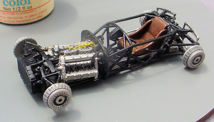
Step three is the construction of the basic chassis and cockpit enclosure.
The base of the chassis is a rectangular frame upon which four vertical
lattice like pieces are attached to the sides. A 'Y' shaped cross member
connects the rear most vertical framework and a smaller rectangular frame
attaches to the tops of the lattice like pieces to form the upper perimeter
of the cockpit enclosure. The firewall is attached to the front of the
cockpit enclosure and the brake, clutch, and throttle pedals are attached to
the firewall. Three photo-etched panels go inside the cockpit representing
the sidewalls and rear bulkhead. An additional photo-etched panel is folded
three ways to form a long rectangular 'U' shape for the driveshaft tunnel
and was glued to the floor of the cockpit. This stage of the cockpit
assembly is completed by the addition of the shifter linkage and what
appears to be the handle for a weight jacking device. The engine,
driveshaft, and transmission are then attached to the frame assembly to
finish the step.
Step four is the assembly of the front suspension. The lower wishbones are
attached to the chassis and the front of the engine and connected to each
other by a transverse leaf spring. The upper wishbones are connected to each
other by another transverse leaf spring and twin shock absorbers are
attached to connect the assembly to the lower wishbones. The tie rod slots
between the upper and lower wishbones and attaches to the spindles that are
molded integrally with the brake drums. The wishbones also attach to the
spindles ensuring the brake drums are perfectly vertical when viewed head on
and are parallel to each other.
Step five has the half shafts inserted into both sides of the differential,
the dampers attached to the rear of the transaxle, and the transverse leaf
spring and sway bar connected to the trailing arms. The rear brake drums are
then glued to the outer ends of the half shafts
and the sway bar.
Step six would have you attach the rear oil tank to the part of the frame
immediately above the transaxle. However, I anticipated an issue with
clearance when it came to attaching the body shell later and did not install
the tank. It turned out that I was correct.
Step seven has photo-etch mesh grills attached to both the front and back
sides of the radiator shroud and the completed radiator assembly attached to
the front of the lower frame. Hoses are glued to the bottom of each side of
the radiator and routed through the front suspension and under the front of
the engine. The hoses exit just behind the front wheels and the outer
(rearmost) ends will later attach to brackets on the inner sides of the
sponsons.
 Step eight has the completed chassis/engine/interior sub-assembly attached
to the belly pan and the seat glued to the floor of the chassis. The bottom
of the seat has channels that the drive shaft tunnel and a chassis cross
member slot into and they must be lined up precosely or the seat will not
drop into place.
Step eight has the completed chassis/engine/interior sub-assembly attached
to the belly pan and the seat glued to the floor of the chassis. The bottom
of the seat has channels that the drive shaft tunnel and a chassis cross
member slot into and they must be lined up precosely or the seat will not
drop into place.
Step nine has the body cowl that surrounds the cockpit attached to the belly
pan (the lower edges of the cowl has pins that are inserted into sockets on
the upper edges of the pan. The five cockpit gauges are glued to the dash
that is cast integrally with the forward edge of the opening for the
cockpit. The gauges have photo-etched bezels with decal faces. I put a drop
of white glue on each face to simulate a glass cover. This step also calls
for attaching the headrest padding and the headrest braces, but I held off
as I was concerned that the headrest padding would get knocked off during
further assembly and that there would be clearance issues with the braces.
This step was completed by attaching the latches to the hood.
Step ten calls for attaching the exhausts to the engine and the body pan,
but again, I held off as I anticipated the likelihood of them getting
knocked off during future assembly steps.
Step Eleven starts with assembling the grill from three layers of
photo-etch; one each of mesh, vertical bars, and a surround and attaching
the grill to the opening in the nose. The step is completed by assembling
the tail fairing from upper and lower halves that trap a vertical bulkhead
inside.
Step twelve is for the assembly of the steering wheel from a white metal
shaft, photo-etched spokes, and a white metal rim. The rim on the real car
was wood and I simulated the wood grain with a base coat of ivory, followed
by a thin and streaky wash of burnt umber oil paint, and topped by a final
coat of a 70/30 mix of Tamiya Clear Yellow and Clear Orange acrylic paints.
The step is finished by cutting the windshield from the of clear butyrate
provided to the size and shape of the template printed on the instruction
sheet. Photo-etched brackets are attached to each lower corner of the
windshield. The brackets will later be attached to .008 mm steel pins
inserted into the sides of the top of the cowl immediately in front of the
dash.
I painted the chassis with Tamiya LP1 black and I painted the body with
Tamiya LP21 Italian Red. I left the remainder of the parts unpainted to
simulate the various natural metal finishes of the real car. I applied a
dark gray oil paint wash on the engine and transaxle and sealed all of the
unpainted metal parts with a coat of Future (or whatever it is currently
named) to eliminate tarnishing. The kit includes decals for the 1955 Monaco
GP for both Ascari's race and qualifying cars and for Castellotti's race
car. I went with the markings for the car Ascari drove in the race.The
decals performed flawlessly and I sealed them with a couple of coats of
Tamiya TS-13 rattle can gloss clear lacquer.
The last step starts with assembly of the wheels. Each wheel has six layers
of photo-etched spokes (two of which have to be formed into shallow cones),
three turned aluminum rims, a turned aluminum hub, and a photo-etched knock
off spinner. I regarded building the wheels with much trepidation, but as it
turned out, it was one of the easier construction tasks. After the wheels
were completed, the tires were slid over the rims and the wheel/tire
assemblies were attached to the brake drums. The tail fairing was then
supposed to slide over the rear suspension and transaxle and be glued to the
belly pan and cowl. However, despite my having test fitted all of the body
panels for clearance of the interior sub-assemblies and to obtain even panel
gaps, when I pushed the tail fairing into place, I began to feel resistance
as if I was compressing a spring. I stopped and checked to see if any of the
rear suspension parts that are externally visible were being
 distorted
and/or moved out of position. When it didn't appear that any were, I went
ahead and glued the tail fairing into place. Each sponson attaches to the
cowl at six points by two white metal tripods and also attaches to the belly
pan in four places with two very thin white metal pins on each side. Since
the sponsons were relatively large and solid white metal pieces, I didn't
think the white metal pins would be sufficient to support them in position
over time and I replaced them with rods that I cut from some .04 mm
stainless steel straight pins. The twin oil coolers were trapped between the
sponsons and the cowl with the forward ends attaching to brackets on the
sponson and the rear ends inserted into slots in the cowl. While attaching
the sponsons and adjusting their locations to get the proper clearance and
alignment with the tires, I managed to break the rear suspension loose. When
I pried off the tail fairing to re-attach the suspension to the belly pan, I
found that most of the rear suspension parts had been distorted when I had
earlier forced the tail fairing into position. After trying unsuccessfully
to bend the parts back into the proper shape and position, I resorted to
desperate measures. I replaced the 'to scale' white metal half shafts with
lengths of steel rods cut from sewing needles. I also replaced the sway bar
with one that I fabricated from a piece of steel wire that I found in my
wife's jewelry making supplies. None of my replacement parts has the detail
that the kit parts had, but they are a lot sturdier and, besides, are almost
completely out of sight when the tail fairing is in place. After making
minor adjustments to the positioning of the modified rear suspension for
alignment with the rear wheels and for clearance with the tail fairing, I
anchored the suspension/transaxle assembly in place with a big wad of Apoxie
Sculpt that I later re-inforced with super glue. After letting the glue and
putty cure for a few days, I re-attached the tail fairing. I finished the
model by attaching the steering wheel, rear view mirrors, exhaust pipes,
fuel filler caps, intake trumpets, and the windshield. I made a base from a
5" x 1/8" pine disc that painted with a spray can of Rustoleum semi gloss
gray paint. I added a Lancia sticker that I bought off of Ebay to give some
reference to the manufacturer of a somewhat obscure old race car.
distorted
and/or moved out of position. When it didn't appear that any were, I went
ahead and glued the tail fairing into place. Each sponson attaches to the
cowl at six points by two white metal tripods and also attaches to the belly
pan in four places with two very thin white metal pins on each side. Since
the sponsons were relatively large and solid white metal pieces, I didn't
think the white metal pins would be sufficient to support them in position
over time and I replaced them with rods that I cut from some .04 mm
stainless steel straight pins. The twin oil coolers were trapped between the
sponsons and the cowl with the forward ends attaching to brackets on the
sponson and the rear ends inserted into slots in the cowl. While attaching
the sponsons and adjusting their locations to get the proper clearance and
alignment with the tires, I managed to break the rear suspension loose. When
I pried off the tail fairing to re-attach the suspension to the belly pan, I
found that most of the rear suspension parts had been distorted when I had
earlier forced the tail fairing into position. After trying unsuccessfully
to bend the parts back into the proper shape and position, I resorted to
desperate measures. I replaced the 'to scale' white metal half shafts with
lengths of steel rods cut from sewing needles. I also replaced the sway bar
with one that I fabricated from a piece of steel wire that I found in my
wife's jewelry making supplies. None of my replacement parts has the detail
that the kit parts had, but they are a lot sturdier and, besides, are almost
completely out of sight when the tail fairing is in place. After making
minor adjustments to the positioning of the modified rear suspension for
alignment with the rear wheels and for clearance with the tail fairing, I
anchored the suspension/transaxle assembly in place with a big wad of Apoxie
Sculpt that I later re-inforced with super glue. After letting the glue and
putty cure for a few days, I re-attached the tail fairing. I finished the
model by attaching the steering wheel, rear view mirrors, exhaust pipes,
fuel filler caps, intake trumpets, and the windshield. I made a base from a
5" x 1/8" pine disc that painted with a spray can of Rustoleum semi gloss
gray paint. I added a Lancia sticker that I bought off of Ebay to give some
reference to the manufacturer of a somewhat obscure old race car.
I'm a sucker for detail and I hold Model Factory
Hiro in high esteem for their uncompromising approach to producing the most
accurate and detailed kit possible for a given subject. However, I feel that
same approach combined with the small size of the model, the extremely close
tolerances, and the high parts count created a challenging and very fiddly
building experience. Nearly every single part had to be modified for fit and I
think some of the individual parts could have been combined into fewer, less
detailed parts for the sake of easier assembly. Particularly in the cases of the
sub-assemblies that were hidden under the body. I'm pleased to have built a
Model Factory Hiro kit, but it may be a while before I take another one on.
Reference: Lawrence, Mike: Grand Prix Cars 1945-65, Motor Racing Publications
Ltd, 1998
Rob Hart
October 2021
Copyright ModelingMadness.com. All rights reserved. No reproduction in part or
in whole without express permission.
If you would like your product reviewed fairly and fairly quickly, please contact the editor
or see other details in the
Note to
Contributors.
Back to the Main Page
Back to the Previews Index Page
Back to the Previews Index Page