Tameo 1/43 Ferrari 375 Indianapolis
| KIT #: | TMK 441 |
| PRICE: | $104.00 |
| DECALS: | One option |
| REVIEWER: | Rob Hart |
| NOTES: | Metal multimedia kit |
| HISTORY |
The Ferrari 375 Indianapolis evolved from an open wheeled, front engined, single seat race car that had competed in the 1950 and 1951 Formula One seasons. Changes in Formula One regulations for 1952 caused the car to no longer be eligible for competition. However, the Indianapolis 500, which was included in the World Championship at the time, was not subject to Formula regulations and Ferrari decided to enter four 375s in the 1952 race. The Ferrari 375 had a 4.5 litre (270 cubic inch) single overhead cam V-12 engine, a four speed transmission, and a tubular chassis. For the Indy 500, the cars had larger carburetors, slightly lengthened wheelbases, and strengthened chassis and suspensions. Although the cars tested well in Europe, they were not up to the challenge of the big Indianapolis oval and only one of the four entered qualified for the race. That car, driven by Alberto Ascari, only lasted 40 laps before retiring with a broken wheel hub and earning a 31st place finishing position. It would be the only World Championship race that Ascari did not win in 1952.
| THE KIT |
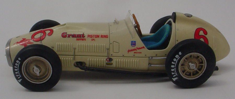
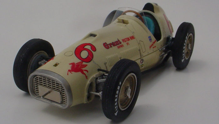
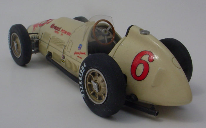
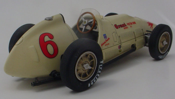 The kit represents the Grant Piston Ring Ferrari
Special (Note: Tameo also makes a kit of the Ascari car) that Johnnie Parsons
unsuccessfully attempted to qualify for the 1952 Indy 500. Parsons had won the
500 in 1950 and was at the peak of his racing career in 1952. Parson's failure
to get the car in the race speaks volumes about its lack of competitiveness. The
kit has 67 white metal parts, 17 photo-etched parts, 4 rubber tires, a length of
insulated small gauge copper wire to represent brake lines, a short length of
brass wire that will be used to simulate a fuel line, a sheet of acetate with
the outlines of two windshields printed on it, two sets of decals, and an
auxiliary decal sheet for the rivets that border some of the body panels. A full
color, seven page instruction booklet has illustrations of all the parts
layouts, paint color call outs, painting and decal guides, one black and white
reference photo, and detailed 23 step construction drawings. The kit is
“curbside” meaning it does not have any engine detail and minimal chassis
detail, It does have a comprehensively detailed cockpit,
The kit represents the Grant Piston Ring Ferrari
Special (Note: Tameo also makes a kit of the Ascari car) that Johnnie Parsons
unsuccessfully attempted to qualify for the 1952 Indy 500. Parsons had won the
500 in 1950 and was at the peak of his racing career in 1952. Parson's failure
to get the car in the race speaks volumes about its lack of competitiveness. The
kit has 67 white metal parts, 17 photo-etched parts, 4 rubber tires, a length of
insulated small gauge copper wire to represent brake lines, a short length of
brass wire that will be used to simulate a fuel line, a sheet of acetate with
the outlines of two windshields printed on it, two sets of decals, and an
auxiliary decal sheet for the rivets that border some of the body panels. A full
color, seven page instruction booklet has illustrations of all the parts
layouts, paint color call outs, painting and decal guides, one black and white
reference photo, and detailed 23 step construction drawings. The kit is
“curbside” meaning it does not have any engine detail and minimal chassis
detail, It does have a comprehensively detailed cockpit,
Tameo kits are the most builder friendly 1/43 race car kits on the market in my opinion. They have crisp and easily cleaned up moldings, are well engineered, have good fit, and feature high levels of detail. All Tameo kits include two complete sets of clear parts and decals which should improves most modelers chances of turning them into finished models.
| CONSTRUCTION |
The kit uses pins and sockets to join most of the parts together. I like to drill out all of the sockets with mini drill bits in a pin vise and then test fit all of the joins. I then cleaned up all of the mold parting lines with 400 grit sandpaper. The body casting had some pitting on one side of the fuel tank fairing. I filled the pits with some brushed on Tamiya White surface primer and sanded them smooth with a multi grit sanding stick.
 Assembly begins with the
rear axle being attached to the cockpit floor/baseplate. The cockpit floor/baseplate
is then glued to the perimeter frame while trapping the rear transverse leaf
spring between them.. The next step entails attaching the shifter, fuel pump,
hand brake, and what appears to be a lever simulating either a brake bias or
chassis adjuster. This step also requires cutting and bending the brass wire to
run from a socket in the fuel pump to a channel in the edge of the cockpit
floor. To that end the instructions provide the length in millimeters that the
wire needs to be cut to and Tameo includes a small white metal block with a
channel engraved in it for bending the wire to the proper shape. The rear brake
lines are also attached to the rear axle in this stage. Again, the instructions
provide the correct length for cutting the provided insulated copper wire. I
found the wire that Tameo provided to be too stiff for bending to shape easily
and substituted some more malleable wire that came in a Pro-Tech 1/25/1/24
ignition wire set.
Assembly begins with the
rear axle being attached to the cockpit floor/baseplate. The cockpit floor/baseplate
is then glued to the perimeter frame while trapping the rear transverse leaf
spring between them.. The next step entails attaching the shifter, fuel pump,
hand brake, and what appears to be a lever simulating either a brake bias or
chassis adjuster. This step also requires cutting and bending the brass wire to
run from a socket in the fuel pump to a channel in the edge of the cockpit
floor. To that end the instructions provide the length in millimeters that the
wire needs to be cut to and Tameo includes a small white metal block with a
channel engraved in it for bending the wire to the proper shape. The rear brake
lines are also attached to the rear axle in this stage. Again, the instructions
provide the correct length for cutting the provided insulated copper wire. I
found the wire that Tameo provided to be too stiff for bending to shape easily
and substituted some more malleable wire that came in a Pro-Tech 1/25/1/24
ignition wire set.
The next four steps continue with completing the cockpit assembly. The seat is attached to a couple of photo-etched braces and then the bottoms of the seat and the braces are glued to the cockpit floor. Pieces representing internal bracing on the sides of the cockpit walls were attached to the cockpit floor on both sides of the seat, The gas, brake, and clutch pedals along with a perforated photo-etched plate that appears to be a footrest were glued to their positions on the cockpit floor. The last two steps in the cockpit sub-assembly were installing the firewall and the photo-etched dashboard. The instructions show the steering wheel and the instrument gauges being attached to the dashboard at this point, but I deviated from the recommended assembly sequence and left them off until after the body had been joined to the chassis.
Before attaching the body to the chassis of open wheel race car models, I prefer to finish applying the paint, decals, and final clear coat to the body to avoid some tedious masking around exposed suspensions and open cockpits.
| COLORS & MARKINGS |
I painted the body with a
50/50 mix of Scalefinishes Racing White and RAL 1014 Ivory. The Scalefinishes
paint dried flat so I applied a couple of coats Mr Color GX 100 Super Clear III
lacquer. The Super Clear III is very thick and I thinned it 75% Mr Color self
leveling thinner to 25% paint. After letting the clear coats dry for a few days,
I started applying the decals. Other Tameo kits that I have built came with
Cartograph decals. There is no indication who/what produced the decals in this
kit, but they look and performed just like Cartograph decals. The only issue
with the decals was caused by me assuming that all three of the race numerals
were the same size when the one on the nose is actually slightly smaller than
the other two. As I'm sure can be guessed, I put the smaller decal on one of the
sides of the fuel tank fairing and let it dry overnight. The next morning I
realized my mistake, and knowing that I had a second set of decals, pulled off
the misplaced decal with a piece of transparent tape. I then applied the rest of
the decals without any
 further problems. One particularly nice detail was a
small black half moon shaped decal that went into the throat of the hood air
scoop to simulate depth and eliminate the see through effect. Tameo also
supplied an auxiliary decal sheet that provides the rivets that go around the
perimeter of the cockpit surround. The rivets are simulated by tiny metal disks
that have to be soaked free of the backing sheet and individually applied. The
rivet decals had a very tenacious adhesive and they did not like being moved
around after being applied, but I managed to get them on and correctly
positioned with a minimum of anxious moments. I didn't need any decal solvent
and after I let the decals dry for 24 hours, I wiped away any excess adhesive
with a damp Q-tip and applied two misted on light coats followed by a heavy wet
coat of the Super Clear III.
further problems. One particularly nice detail was a
small black half moon shaped decal that went into the throat of the hood air
scoop to simulate depth and eliminate the see through effect. Tameo also
supplied an auxiliary decal sheet that provides the rivets that go around the
perimeter of the cockpit surround. The rivets are simulated by tiny metal disks
that have to be soaked free of the backing sheet and individually applied. The
rivet decals had a very tenacious adhesive and they did not like being moved
around after being applied, but I managed to get them on and correctly
positioned with a minimum of anxious moments. I didn't need any decal solvent
and after I let the decals dry for 24 hours, I wiped away any excess adhesive
with a damp Q-tip and applied two misted on light coats followed by a heavy wet
coat of the Super Clear III.
While the final clear coat was drying, I painted the rest of the parts that required paint. I painted the seat with Tamiya Acrylic Blue X-3 and drybrushed it with Testors Lt Blue 1108. The rear shock absorbers, head rest, fuel tank retaining strap, and clutch and brake pedals were painted with Tamiya Acrylic XF 69 Nato Black. The rear axle, brake drums, and one side of the cockpit interior bracing was painted with Tamiya Lt Gray XF 66. I painted the exhaust pipes with Alclad II Jet exhaust and then lightly rubbed them with the a #2H pencil lead to impart a metallic sheen. I gave the outer face of the wheels a coat of Tamiya Acrylic Titanium Gold X-31 followed by a wash of Paynes Grey oil paint. I simulated the wood grain of the steering wheel rim by painting it with a 90/10 mix of Tamiya acrylic white X-2 and Tamiya Desert Yellow XF-59, then applying a thin streaky wash of burnt umber oil paint, and finishing with an overcoat of a 70/30 mix of Tamiya Acrylic Clear Yellow X-24 and Tamiya Acrylic Clear Orange X-26. The rest of the of the parts had either a natural metal or silver finish and I left them unpainted. I felt like the white metal parts and the nickel plated photo-etched parts simulated actual metal better than I could accomplish with paint. I did apply a coat of Future to the unpainted kit parts to prevent tarnishing and oxidation. I also applied a Paynes Grey oil paint wash to the unpainted suspension and cockpit parts to simulate depth and shadows. I brushed a coat of Future on one side of the tires to provide a smooth surface for the tire decals (note: you have to use an acylic or lacquer clear coat on rubber or vinyl surfaces- enamel paint/clear coats will not dry). After the Future had dried for 24 hours I applied the decals. They laid down over the compound curves of the tire's sidewalls with no drama.
| FINAL CONSTRUCTION |
Before attaching the body to the base plate, a curved metal piece simulating the top and forward side of the fuel tank along with its photo etched retaining strap were glued to the top of the inside of the body immediately behind the cockpit opening. The body is attached to the chassis/base plate assembly by two small phillips head screws. The screws pass through holes at the front and rear of the base plate and into posts cast in the inside of the body. I drilled the openings in the posts for the screws a little deeper to make certain that the interface between the body and base plate was snug.
With the body and base plate joined, the mounting blocks for the front suspension, the, front transverse leaf spring, and the driveshaft were glued to the underside of the base plate. A part representing the lower side of the engine was attached to the base plate followed by three pieces representing the belly pan. The front suspension comprising parts representing upper and lower wishbones, shock absorbers, spindles, the tie rod, and the steering arm was assembled next. Moving towards the rear of the car, the exhaust pipes, the rear radius arms, the rear shock absorbers, and a pair of photo-etched brackets linking the rear axle and the transverse leaf spring were attached.
 The nose of the car is a
separate piece that slides over a plug cast on the forward end of the rest of
the body. This join had a slight mis-alignment that I cured by grinding out the
inside of the nose piece with a Dremel. After the alignment issue was resolved,
the nose was attached, the photo etched grill was glued to the nose, a
rectangular photo etched plate was attached to the grill, and a .4 mm diameter
by 4 mm length steel pin representing the crankshaft extension for the remote
starter was inserted into a hole in the photo etched plate. The grill surround
was an unpainted white metal piece that I had buffed to a shine by rubbing it on
a piece of an old cotton dishrag. A flange running around the circumference of
the back side of the surround fitted neatly into a recess on the front of the
nose piece. The fit was so close that I didn't use any glue.
The nose of the car is a
separate piece that slides over a plug cast on the forward end of the rest of
the body. This join had a slight mis-alignment that I cured by grinding out the
inside of the nose piece with a Dremel. After the alignment issue was resolved,
the nose was attached, the photo etched grill was glued to the nose, a
rectangular photo etched plate was attached to the grill, and a .4 mm diameter
by 4 mm length steel pin representing the crankshaft extension for the remote
starter was inserted into a hole in the photo etched plate. The grill surround
was an unpainted white metal piece that I had buffed to a shine by rubbing it on
a piece of an old cotton dishrag. A flange running around the circumference of
the back side of the surround fitted neatly into a recess on the front of the
nose piece. The fit was so close that I didn't use any glue.
The front brake drums were glued inside the inner halves of the wheel halves and then the completed assemblies were glued to the axles. Simulated brake lines were formed from 7 mm lengths of the insulated wire,.The opposite ends of the wires were then glued in holes drilled into the body and the backs of the brake drums respectively. This process was repeated at the rear axle with the exception of only the outer ends of the simulated brake lines needing to be attached to the brake drums as the inner ends had been glued to the rear axle earlier in the construction. The wheel/tire assembly was finished by sliding the tires over the outer wheel halves with the decal sides out, gluing the outer wheel halves to the inners, and attaching the knock off wheel nuts.
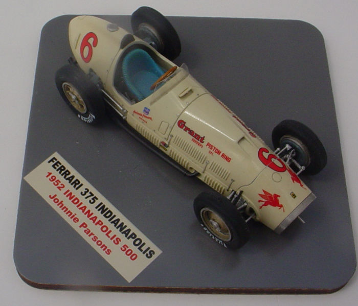
Once the car was sitting on its wheels, I attached the steering wheel, the instrument gauges (decals on photo-etched bezels with drops of Future on the decal faces to simulate glass), The headrest, the fuel filler cap, the vent panel forward of windshield, and the six photo-etched hood retaining straps. I left the windshield for the last part to be attached I formed the windshield to shape by bending it around the handle of a JLC saw held in the steam coming out of the spout of a boiling tea kettle. I then glued the base of the windshield into a groove cast into the body just forward of the cockpit opening. I made a base from a $.99 die cut piece of laminated pine that I bought at Walmart, painted it gray with a can of Rustoleum spray paint, and applied the decal that came in the kit.
| CONCLUSIONS |
A fast and fun build. 1/43 open wheel race car models can be very fiddly to assemble, but this one was stress free. The combination of clever engineering, good fit, simple color scheme, and clear instructions makes this kit easy to recommend for modelers with any experience building multi media kits.
7
February 2023 Copyright ModelingMadness.com. All rights reserved. No
reproduction in part or in whole without express permission. If you would like your product reviewed fairly and
fairly quickly, please
contact
the editor
or see other details in the
Note to
Contributors.