AMT 1/25 1953 Studebaker Starliner
| KIT #: | A1251 |
| PRICE: | $25.00 |
| DECALS: | One option |
| REVIEWER: | John Summerford |
| NOTES: | Option to build one of three versions |
| HISTORY |
Courtesy of Classic Driver
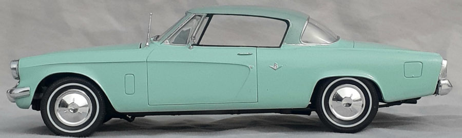
 Studebakers boasted spectacular styling for 1953 courtesy of designer Bob
Bourke of the Raymond Loewy studio based in Studebaker’s hometown of South Bend,
Indiana. The dramatically sleek car, inspired by the Lockheed Constellation, was
astoundingly low by 1953 standards at just 56.3 inches high while accentuated by
a long 120.5 wheelbase. The drive train was a 232-cid, 120-hp V-8 and automatic
transmission. What should have been a magnificent sales year for Studebaker,
turned out to be a rather ho-hum one at-best. Studebaker focused more on sedans
rather than coupes, and production ills developed as front-end sheet metal
failed to fit the coupe body at first. Demand for the new coupes outpaced sedans
four-to-one catching Studebaker product planners off-guard while a strike at the
Borg Warner plant curtailed availability of automatic transmissions. The car
received numerous design awards and today serves as a landmark of modern design.
19,236 Commander Starliner Coupes were produced for the model year of a total
151,576 Studebakers; fewer than the 1952 model year, dropping the company to
tenth in industry sales.
Studebakers boasted spectacular styling for 1953 courtesy of designer Bob
Bourke of the Raymond Loewy studio based in Studebaker’s hometown of South Bend,
Indiana. The dramatically sleek car, inspired by the Lockheed Constellation, was
astoundingly low by 1953 standards at just 56.3 inches high while accentuated by
a long 120.5 wheelbase. The drive train was a 232-cid, 120-hp V-8 and automatic
transmission. What should have been a magnificent sales year for Studebaker,
turned out to be a rather ho-hum one at-best. Studebaker focused more on sedans
rather than coupes, and production ills developed as front-end sheet metal
failed to fit the coupe body at first. Demand for the new coupes outpaced sedans
four-to-one catching Studebaker product planners off-guard while a strike at the
Borg Warner plant curtailed availability of automatic transmissions. The car
received numerous design awards and today serves as a landmark of modern design.
19,236 Commander Starliner Coupes were produced for the model year of a total
151,576 Studebakers; fewer than the 1952 model year, dropping the company to
tenth in industry sales.
| THE KIT |
Frequent readers may suspect that I’m not much of a car guy, so it took some packaging to get my attention. While cruising the website of my (nearly) LHS, the photo of the lid to this tin box and the headline caught my attention. Readers may also suspect that I gravitate to more unusual subjects, so when the package appeared on my doorstep, I quickly tore into the box.
 My first observation was that the parts are nicely packed into 12 bags. The
second observation was that this is very much a mid-60s mold. Little flash is
present on my example, but there are heavy seamlines to clean up. Round 2
proudly notes in the preamble to the instructions that the sprue gates on the
chromed pieces are on the back side of the parts. It looks to me that many of
the seams are also strategically located.
My first observation was that the parts are nicely packed into 12 bags. The
second observation was that this is very much a mid-60s mold. Little flash is
present on my example, but there are heavy seamlines to clean up. Round 2
proudly notes in the preamble to the instructions that the sprue gates on the
chromed pieces are on the back side of the parts. It looks to me that many of
the seams are also strategically located.
The total parts count is 113, but which parts are used depends of which version one chooses to build--stock, custom, or racer. The custom version will require some surgery to lower the roof. It, and the racer, use the tinted window parts. The tires are vinyl and come with a white-wall trim that looks to be too narrow.
The first step calls for building the engine, either standard or racer. Spark plug wires are not supplied. The next two steps concern the chassis-wheels, then the interior. The instructions are clear as to which parts to use for which version. A metal axle is provided for the rear wheels and a complete suspension is built up for the front wheels and should be able to posed in a turn. There are no decals for the dashboard. Color notes are generic, indicating paints such as “steel”, “black”, or “interior color”. What interior, or exterior, color to use is left up to the imagination. Step four is the body assembly and the final step is about external details that depend on the chosen version.
| CONSTRUCTION |
More than an hour-and-a-half was spent cleaning the seams on the body, interior tub, and chassis to start the build. Repeated test fits of the three pieces were done and a build strategy began to form. The first piece glued was the front stock pan, which sits below the bumper, onto the body, as called for in Step 4. The seams on the side were filled and sanded smooth.
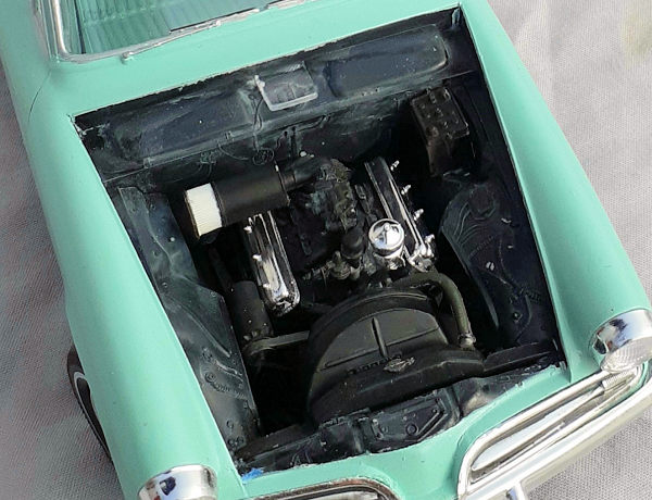
Satisfied, the engine was assembled. Examining the illustration closely, I noticed that the cylinder head pieces are handed. Part 3 is the right bank and part 4 the left. The intake manifold is keyed to heads and the instructions don’t mention that. The chromed pieces were left off to be added until after painting. Some parts needed to have their mold seams cleaned up before gluing.
After setting the engine aside, the front wheels were assembled. The fit of the inner wheel rims and the hub caps to the vinyl tires was loose enough that some glue had to be added from the inner faces. Brake drums and backing plates were glued to the inner wheel rims, then each wheel assembly glued to kingpins. I read the diagram as indicating that the kingpins are handed, but that may not make much of a difference. I’m not sure if the engineering is supposed to allow for the wheels to roll., Regardless, I glued them into a solid assembly.
 The coil springs were glued to the frame. I deviated from instructions (of
course I did) and skipped press fitting the tie rod ends to the kingpins and
instead glued the lower A-frames stabilizer bar piece to the frame, then snapped
the kingpins between A-frame mounts. Before placing the idler arm in place, I
had to add a piece of rod to replace a missing pin.
The coil springs were glued to the frame. I deviated from instructions (of
course I did) and skipped press fitting the tie rod ends to the kingpins and
instead glued the lower A-frames stabilizer bar piece to the frame, then snapped
the kingpins between A-frame mounts. Before placing the idler arm in place, I
had to add a piece of rod to replace a missing pin.
Doubling back to the tie rods, I pressed one in place for the left wheel and found that it swiveled nicely to pose the wheel in a turn. The tie rod on the right side was so loose that, again, I had to glue it place, locking both wheels into a shallow left turn.
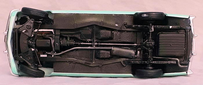
Masking was wrapped around the wheels so that the suspension, frame, and engine could be sprayed semi-gloss black. When the paint cured, the chromed distributor cap was glued to the engine, then a scratch-built spark plug harness glued to each cylinder bank. (It is so difficult to see that I wonder if it was worth the effort.) The valve covers and oil filter were glued in place, completing the engine.
Once the engine was glued in place, the exhaust system was installed. The head pipe didn’t mate cleanly with the exhaust manifold, so gap filling cyano anchored that end. The gap for the cross over pipe was worse, so a dab of filler reinforced with cyano filled it. Next came the installation of the rear wheels and suspension. When building up the wheels I realized that I had installed the inner rings on the front wheel incorrectly, with the wrong side facing outward. By turning the ring over, I got a nice, tight, fit inside the tire. The last piece to install on the chassis was the drive shaft. Trimming on both ends was needed to get it to fit.
| COLORS & MARKINGS |
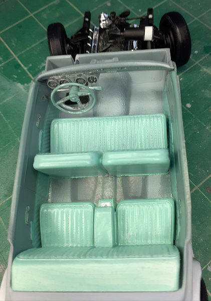 Before gluing anything together in the interior, the upholstery and sides
were primed then masked and painted in a two-tone blue scheme. The carpet, back
shelf, and dash were sprayed light gray and the chrome trim in the dash, along
with the window cranks were swiped with a felt tip chrome paint pen. The dials
were given a wash of black then a white artist’s pencil was drawn over the
raised numbers.
Before gluing anything together in the interior, the upholstery and sides
were primed then masked and painted in a two-tone blue scheme. The carpet, back
shelf, and dash were sprayed light gray and the chrome trim in the dash, along
with the window cranks were swiped with a felt tip chrome paint pen. The dials
were given a wash of black then a white artist’s pencil was drawn over the
raised numbers.
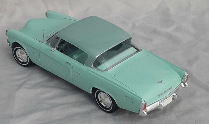
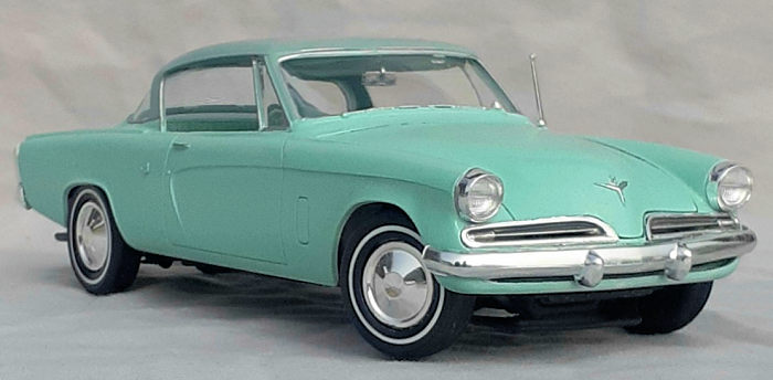
The car body has the same colors as the interior, so the lower body was masked for the painting of the roof’s darker color. Unfortunately, while painting the roof, some pieces of lint landed on the wet paint, so those areas needed to be sanded and re-painted. My preference is to wet-sand so that loose particles won’t clog the sandpaper. Either I used too much water, or I sanded too vigorously, or some combination of the two, but the result was a spectacular chipping effect, which would be great for an armor model.
So, more primer was sprayed on, then sanded, repeat, and get more chipping. After the fourth time not getting good results, I decided that what I was doing bordered on the definition of insanity so the roof was stripped down to bare plastic to start over. (I guess this proves that, while we modelers may go to extreme lengths for our hobby, were not crazy.)
When the roof was finely done, it was masked and the lower portion of the body was successfully painted, then a hole drilled for the radio antenna. The raised chrome detail was giving a carful swipe with the chrome pen, a very quick and easy way of highlighting the detail. The windshield wipers are molded into the body making it easy to use the side of a brush to paint the rubber wipes. A gloss coat was then sprayed over the entire body.
| FINAL CONSTRUCTION |
Returning to the interior, the parts dropped into place without any fuss. The steering wheel was installed rotated slightly to the left to match the front wheels. Note that the steering shaft doesn’t connect with the front wheels. I don’t know enough about the linkage to scratch build the parts, so I left it alone. The interior tub was then glued to the frame.
Moving on to the next step, the clear hinge piece for the hood was threaded through the firewall and floats in place. It would be nice if the pivot pins snap into a recess, but they don’t. The instructions call for gluing the hood to the hinge. I saved that for after attaching the body to the chassis. The engine compartment is completed by inserting the battery, radiator, and its shroud.
 After putting on some latex gloves, the clear windows were removed from the
sprues and maneuvered into place. The fit was good enough to flow liquid cement
in spots to secure them. The review mirror butt fits to the roof behind the
windshield.
After putting on some latex gloves, the clear windows were removed from the
sprues and maneuvered into place. The fit was good enough to flow liquid cement
in spots to secure them. The review mirror butt fits to the roof behind the
windshield.
Despite the many test fittings at the beginning of the build, I had to take a deep breath before trying a test fit of the built-up body to the built-up chassis and interior. It was a good thing that I didn’t bother to complete the steering linkage because the steering wheel shaft interfered with the firewall. so that was clipped of by the sprue cutters. There are positive locating bumps on the body and dimples on the frame ahead of the front wheels, but the back end doesn’t have any locating points. After the glue had cured at the front, the rear bumper was used as a guide to identify where to glue the body to the rear wheel well.
Somehow, the hood hinge piece became locked in the closed position. Now the hood just floats in place so that the engine can be viewed. The last mechanical piece to attach was the upper radiator hose. (There is no lower hose supplied.) This piece didn’t fit well, but some dabs of cyano glue filled the gaps. The hose was painted a rubber color and the hose clamp details aluminum.
I wondered if it would be better to add the chrome pieces to the body before attaching it to the chassis, or follow the instructions and install them in the final step. I followed the instructions and everything worked out well. The lenses were glued to the headlight trim, then to the body. The grills lay in their recesses, so cyano was smeared there and the pieces dropped into place. Cyano was also smeared along the upper lips of the body for the bumpers. The tail lights and the radio antenna were glued in place and the final piece was the side view mirror.
| CONCLUSIONS |
 I don’t recall ever reading the name of a part as; “Lower A-frames stabilizer
bar” before this build and that added to the exoticness of this experience for
me. Your esteemed editor indicated to me that he considers AMT to be a
second-tier car kit manufacturer and I feel that way regarding their aircraft
kits. The clean-up and fit issues encountered with this build supports that
opinion. However, the car body molding is very good and that makes up for
problems under the hood. If I had more experience with car kits, I might have
had an easier time with it, but I didn’t encounter any surprises or major
issues. If I were to build another stock factory engine, I’d probably strip off
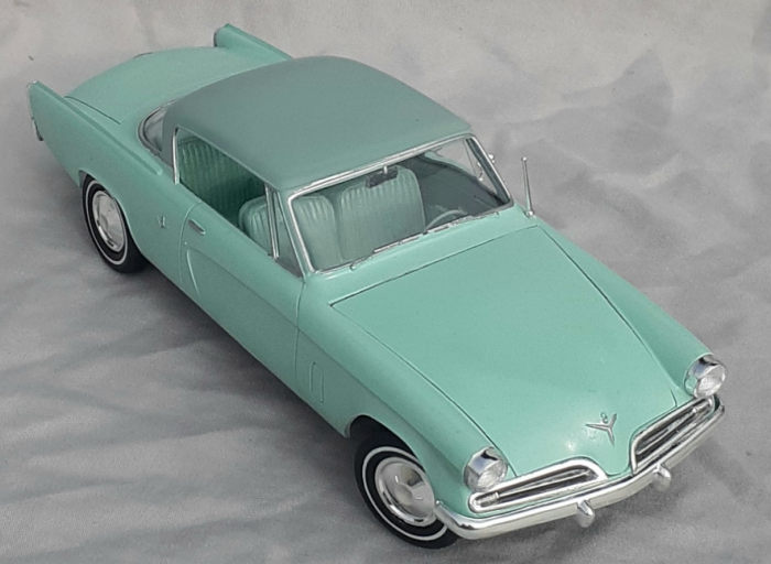
the chrome finish and brush on some paint. I’m pleased with the stylishness of
the Starliner and the roughly 30 hours spent on the build was enjoyable. The
last car model I built was Mobius’ 1953 Hudson Hornet. The two contemporary cars
make a striking pairing on the shelf.
I don’t recall ever reading the name of a part as; “Lower A-frames stabilizer
bar” before this build and that added to the exoticness of this experience for
me. Your esteemed editor indicated to me that he considers AMT to be a
second-tier car kit manufacturer and I feel that way regarding their aircraft
kits. The clean-up and fit issues encountered with this build supports that
opinion. However, the car body molding is very good and that makes up for
problems under the hood. If I had more experience with car kits, I might have
had an easier time with it, but I didn’t encounter any surprises or major
issues. If I were to build another stock factory engine, I’d probably strip off
the chrome finish and brush on some paint. I’m pleased with the stylishness of
the Starliner and the roughly 30 hours spent on the build was enjoyable. The
last car model I built was Mobius’ 1953 Hudson Hornet. The two contemporary cars
make a striking pairing on the shelf.
24 June 2022 Copyright ModelingMadness.com. All rights reserved. No
reproduction in part or in whole without express permission. If you would like your product reviewed fairly and
fairly quickly, please
contact
the editor
or see other details in the
Note to
Contributors.