ICM 1/48 Henschel Hs-126A-1
| KIT #: | |
| PRICE: | |
| DECALS: | 3 options |
| REVIEWER: | Michael Rohde |
| NOTES: |
| HISTORY |
In 1935 Henschel developed the parasol- wing Henschel Hs 122 short range reconnaisance aircraft as a replacement for the Heinkel He 45 and 46. Only a few of the 600 hp Siemens SAM 22 B engined Hs 122's were built and this type was not adopted for service in the Luftwaffe.
Henschel's chief designer
Friedrich Nikolaus derived the Henschel Hs 126 which incorporated a new wing,
cantilever main landing gear and a canopy over the pilot's cockpit. The Hs 126
prototype was converted from a Hs 122 A airframe and first flown in autumn 1936.
This aircraft was powered by a 610 hp Junkers Jumo 210 engine. It was followed
by two further development aircraft , both powered by the 830 hp Bramo Fafnir
323 A1 radial engine . The first was equipped with an engine supercharger and
enlarged vertical tail surfaces, while the second had modified main landing gear
legs. During 1937 Henschel built 10 pre
 production Hs 126 A-0 aircraft
based on the third prototype, and some were used for operational evaluation by
the Luftwaffe's Lehrgruppe reconnaisance unit in the spring of 1938.
production Hs 126 A-0 aircraft
based on the third prototype, and some were used for operational evaluation by
the Luftwaffe's Lehrgruppe reconnaisance unit in the spring of 1938.
The production version was the Hs 126 A-1, powered by the 880 hp BMW 132 Dc radial engine. Armament comprised of on forward firing 7.92 mm MG 17 , plus one similar weapon on a trainable mounting in the rear cockpit. Five 10 kg or one single 50 kg bomb could be carried on an underfuselage rack. A hand held Rb 12.5/9x7 camera in the rear cockpit was supplemented by a Zeiss camera in a rear fuselage bay.
Six of these Hs 126 A-1 's were used by the Legion Condor in Spain during 1938, being later transferred to the Spanish Air Force , and sixteen Hs 126 A1's were delivered to the Greek Air Force. An improved but similar Hs 126 B 1 was introduced during the summer of 1939, this incorporating FuG 17 radio equipment and either the 830 hp Bramo 323 A-1 or the 900 hp 323 A 2 radial engine. Production aircrafr were built in Berlin at the Schoenefeld and Johannisthal factories from 1938 and entered operational service with Aufklaerungsgruppe 35. By the outbreak of WW 2 the re -equipment of the He 45 and 46 units with the Hs 126 was well under way.
During 1942 the Hs 126 was progressively withdrawn from front line service on replacement by the Focke Wulf FW 189, but a few examples were still in service by the end of WW 2. Just over 600 Hs 126 's were built.
| THE KIT |
The kit contains 4 frames with 139 parts in light grey plastic plus one frame with 5 parts in clear plastic. The windshield and canopy are quite thin --- translucency is reasonably good. Panel lines are recessed although a bit inconsistent in places ( some lines are engraved deeper than others – in particular on the fuselage halfes where the panel lines meet. Cockpit detailing is very good and can be well spotted due to the spacious cockpit area after the model is finished .
 There are no locator pins
so care has to be taken in aligning parts. Unfortunately we have to deal with
sinkmarks ( ( fuselage keel surfaces and top wing ) which need to be remedied.
The thin supporting struts are a bit vulnerable to breaking since the plastic is
a bit brittle ---- care has to be taken when separating them from their sprues.
( in my case I had to repair a couple of these)
There are no locator pins
so care has to be taken in aligning parts. Unfortunately we have to deal with
sinkmarks ( ( fuselage keel surfaces and top wing ) which need to be remedied.
The thin supporting struts are a bit vulnerable to breaking since the plastic is
a bit brittle ---- care has to be taken when separating them from their sprues.
( in my case I had to repair a couple of these)
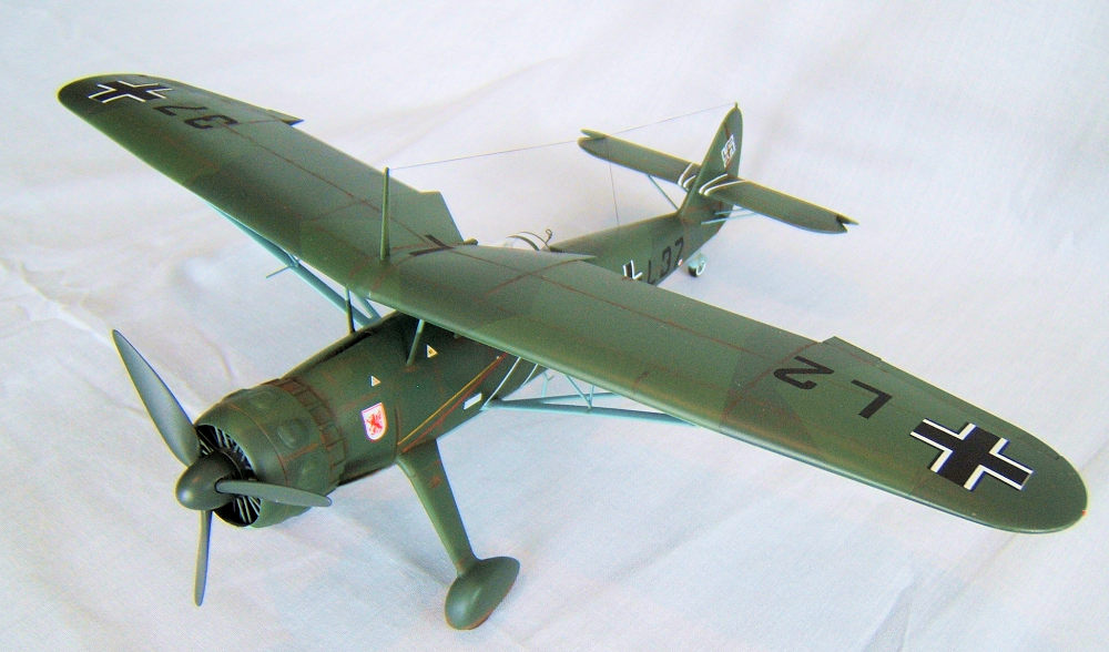
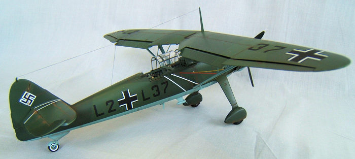
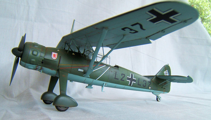
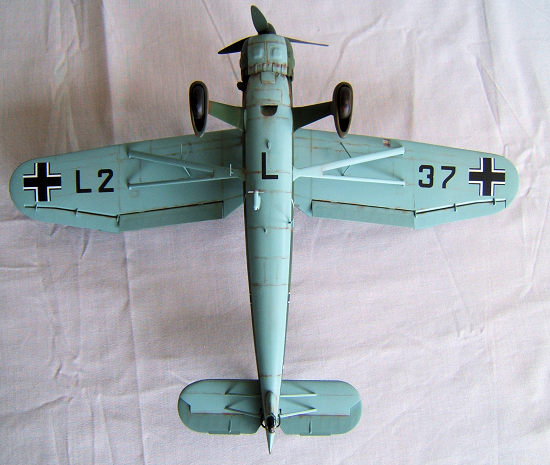
Decals are supplied for 3 different units , these being : 9.(H) Lehrgeschwader 2 Germany 1939, 1.(H ) 14 Poland September 1939, and 2.(H) 31st Panzer Greece April 1941.
The quality of the decals is satisfactory . There is a bit of inkwash on the lettering and the crosses have to be trimmed carefully. ( white outline showing on the black edges). The alignment markings on the fuselage are especially delicate .
ICM's instruction sheets are a bit tricky . One has to go back and forth to identify (esp small) parts by referring to the page where we can see part numbers on the individual frames. There are no number tags on the frames to help us identifying bits more easily. ICM has been quite particular with the fact that the tail plane and fin on the Hs 126 were offset by 3 degrees to port to compensate for engine torque and one can clearly identify this detail on the model.
| CONSTRUCTION |
As per plan I began with the cockpit. All the items to be fitted to the cockpit side walls were carefully removed from their respective sprues, cleaned up and according to their number on the instructions-glued into place. Some of these parts are extremely small-- ie the levers for flaps throttle and mixture measure at most 1.5-2 mm in length and difficult to handle. So a pair of fine pointed tweezers and magnification are very helpful to fit these tiny items.
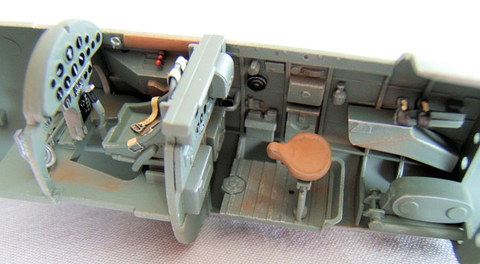 The actual cockpit floor-
together with the rear bulk head pilot's seat , rudder bar' control column and
observers instrument panel were assembled. The aft cockpit floor and the Zeiss
Camera on its frame were – like all the other parts-- glued into place before
painting. The front bulk head carrying the instrument panel and associated
consoles were assembled as well .
The actual cockpit floor-
together with the rear bulk head pilot's seat , rudder bar' control column and
observers instrument panel were assembled. The aft cockpit floor and the Zeiss
Camera on its frame were – like all the other parts-- glued into place before
painting. The front bulk head carrying the instrument panel and associated
consoles were assembled as well .
Now I encountered my first problemk, This was the firewall with the engine mounts and the engine carrier plate. The individual v shaped engine bearers are clearly marked with numbers on the plan but there was no other way than to dry fit the V's in order to get the engine carrier plate centered ( and hence properly aligned to the opening in front of the fuselage. To get the dry fitting business right , I carefully drilled the locating holes to achieve a kind of press fit to help me keeping the bearers aligned without falling off. This took quite some time and after careful insertion into the fuselage shells ( securing things with masking tape) I was happy with everything and drops of superglue secured the structure.
Having that out of the way I could then proceed to airbrush all cockpit interior items with RLM 2 and painted all the fine details ( instruments ,radio set etc) under 10 fold magnification. A bit of careful dry brushing and weathering with Pastel colours as a finishing touch and it was time to close up the fuselage.Tamiya putty was applied along the seams, carefully sanded down and panel lines re engraved where necessary.
I carried on with preparing the engine parts incl cowls,cowling ring and complete propeller ,wheels , main landing legs plus spats, all struts , tailplane , main parasol wing for further assembly. Engine , wheels , cowl and spat interior surfaces were painted and while drying, I glued the tailplane with elevators in down position into place . The fit was not perfect and putty was needed to clean up the seams. That done I glued the four supporting struts into place and carried on with putting the main wing together. This was remarkably easy as far as the fit was concerned and only small amounts of filler was required to clean up the leading and trailing edges.
 As far as the fit of the
main wing and wing struts is concerned: It is very important to dry fit these
parts because the locating holes are a tat too small and need to be opened up.
Otherwise we end up with quite a gap and a difficult job to fix this with putty.
That step was also necessary with the attachment points of the main landing gear
legs on the fuselage .
As far as the fit of the
main wing and wing struts is concerned: It is very important to dry fit these
parts because the locating holes are a tat too small and need to be opened up.
Otherwise we end up with quite a gap and a difficult job to fix this with putty.
That step was also necessary with the attachment points of the main landing gear
legs on the fuselage .
Back to the engine and cowlings. While looking at the instructions this seems to be straight forward and easy –BUT—it is not!! I tried to figure out which way would be best and came to the conclusion that it was necessary to begin with cementing the cowling ring supports into the ring and to make sure that these are in the correct right angle because this would determine how good the 3 cowling plates and the cooling gill ring would align with a minimum of gap. To make it possible to slide the complete engine cover assembly over the radial engine I had to remove a bit of material off the cylinders. In the end it all worked out-- starting with the perfect alignment of the engine bearers to attaching the engine in the right position on the engine bearer plate and finally to the proper alignment of the cowling in line with the fuselage.
Having done that ,I glued the landing gear legs into place and later added the assembled spats and wheels.
Before I proceeded to installing the wing , I made sure that the canopy and wind shield fitted nicely. The canopy slides on rails. The problem here is that the frame is solid and has no recess to fit onto the rails. So I had no other choice but toI scoop out the supporting frame of the canopy to make it fit properly onto the rails using dental technicians drills.
 Afterwards I hand painted
wingshield and canopy , let dry and glued the windshield into place. Next I
measured the distance between the cabane strut attachment points on the wing
with a compass and used this measurement to make sure that the cabane struts
were glued into place at the correct angle. Then I took a piece of stiff white
cardbord and drew a cross on it. This I used to align and fix the wing along the
horizontal line on the cardbord surface with masking tape.
Afterwards I hand painted
wingshield and canopy , let dry and glued the windshield into place. Next I
measured the distance between the cabane strut attachment points on the wing
with a compass and used this measurement to make sure that the cabane struts
were glued into place at the correct angle. Then I took a piece of stiff white
cardbord and drew a cross on it. This I used to align and fix the wing along the
horizontal line on the cardbord surface with masking tape.
In the meantime the glue on the cabanes had set and I inserted the cabane struts into their respective recesses in the wing and checked that the fuselage was nicely aligned with the vertical line of the cross. Then I secured this position with masking tape and glued the cabane struts into the wing. I left everything alone overnight and carried on the next day with cementing the remaining struts into place. This was quite easy since the correct alignment of the wing was now secured by the cabane struts. It certainly paid to have done a thorough dry fitting of the struts before cementing . There was such a small gap which was filled easily with a bit of excess glue.
| COLORS & MARKINGS |
The time had come to prepare for painting the model starting with masking off the entire cockpit area , windshield ,wheels and the cowl ring opening. The tail wheel assembly was prepainted and put aside .Then I airbrushed the undersides with Tamiya XF 23 light blue and left to dry overnight.
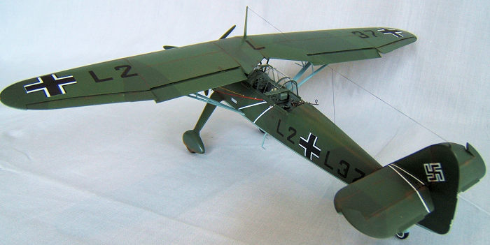
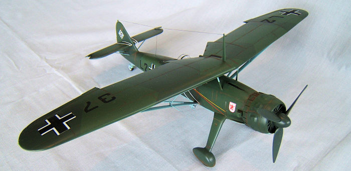 The next step was to mask
off the entire underside of the model and went on to airbrush the model all over
with RLM 71 ( a mix of Tamiya XF 6 dark green XF 5 flat green and XF 2 flat
white ) and left to dry overnight. I masked off the splinter camouflage scheme
and airbrushed the remaining surface with Tamiya XF 6 dark green ( I added a bit
of XF 2 flat white XF 6 is a bit too dark in colour). I left that to dry
overnight and the next day I removed all the masking tape carefully and touched
up a few spots of overspray where the masking tape had lifted a bit.
A overall coat of thinned down Tamiya gloss clear was
applied to prepare a smooth surface for the decals.
The next step was to mask
off the entire underside of the model and went on to airbrush the model all over
with RLM 71 ( a mix of Tamiya XF 6 dark green XF 5 flat green and XF 2 flat
white ) and left to dry overnight. I masked off the splinter camouflage scheme
and airbrushed the remaining surface with Tamiya XF 6 dark green ( I added a bit
of XF 2 flat white XF 6 is a bit too dark in colour). I left that to dry
overnight and the next day I removed all the masking tape carefully and touched
up a few spots of overspray where the masking tape had lifted a bit.
A overall coat of thinned down Tamiya gloss clear was
applied to prepare a smooth surface for the decals.
I choose the markings of a Hs 126 serving with 9.( H) Lehrgeschwader 2 Germany 1939. The decals in this kit are not of the best quality but usable. A bit of ink wash in places and the crosses needed to be trimmed at the edges to get rid of a thin white rim. The fuel and oil filler triangles were no good and replaced these with some I had in my decals stash. To seal the decals I gave the entire model a thin coat of Humbrol Satin clear. Mild weathering was done using Pastel colours.
| CONCLUSIONS |
This kit is not bad . It requires a bit of extra work but the effort is rewarded by giving us a nice model of a German short range reconnaissance plane .
23 March 2018
Copyright ModelingMadness.com
If you would like your product reviewed fairly and fairly
quickly, please
contact
the editor
or see other details in the
Note to
Contributors.
Back to the Main Page
Back to the Review Index Page
Back to the Previews Index Page