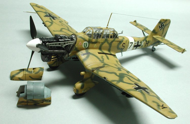
Hasegawa 1/48 Ju-87B-2 'Desert Stuka'
|
KIT # |
JT 16 |
|
PRICE: |
$40.00 AUD |
|
DECALS: |
Two Aircraft |
|
REVIEW BY: |
|
|
NOTES: |
Use of Aires aftermarket cockpit/engine highly recommended – just be aware that the engine length is slightly too long to refit the engine covers (Aires kit No.: 4801) |
|
HISTORY |

The Stuka was one of the most feared and loathed of any aircraft that flew during WWII. With it’s wailing scream as it plunged earthward to deliver its load of one 500kg SC500 bomb and four 50 kg SC50 wing-mounted bombs, it managed to strike fear into anyone on the receiving end of its attack. That was until it was unleashed on the British in the initial opening of the war on England. It was soon found to be wanting against the likes of the Spitfire and the Hurricane and invariably came off second best unless accompanied by an escort.
Such was the lack of success against the British that the Stuka’s future was under a cloud until the Eastern front and Desert campaigns saw it applied with renewed vigour and destructive capabilities. It re-gained its fearsome reputation with all the troops upon which it was used, many running for cover under the deadly accuracy of the bombing runs.
Prior to the commencement of hostilities the Stuka had enjoyed an almost trouble free birth and baptism. It was used with the Condor Legion in the Spanish Civil war and was relatively unmolested during its application. It was in this conflict that it gained the reputation as an accurate, sturdy bombing platform able to able to withstand a fair degree of punishment.
The Junkers Ju 87 began development as a dive-bomber following Ernst Udet, a former WWI ace, attending an exhibition in the USA in the early thirties. As a result of a dive-bombing competition held in Germany in 1936, where the finalists were the Arado AR81, Blohm & Voss HA 137, Heinkel He 118 and the Ju 87, Udet almost came to grief when the propeller and gearbox on the Heinkel ran away. He managed to parachute to safety but sustained minor injuries. The Junkers could dive at almost 90 degrees, and recover with ease, but was 70 km/h slower than the Heinkel. It didn’t fall out of the sky, however and became the aircraft of choice.
The initial production Ju 87 A-0 was powered, or rather underpowered, by the Junkers Jumo 210CA. The later A-1 and 2 versions used an engine with less than 700hp. The Ju 87B-0 went into mass production in 1938 with the improved Jumo 211A, which had an output of 1000hp. The B series had the same wing and tail surfaces as the initial models but the fin/rudder and fuselage had been completely revamped.
When the B-2 was put into production it used the Jumo 211Da engine that had a pressurized radiator, larger propeller and exhaust stacks that pointed rearwards. All these combined to give an increased top speed of 383km/h at 3,700m. The type deployed to the Mediterranean and desert theatres also had minor modifications to handle the harsh sandy and tropical environments.
|
THE KIT |
On first opening of the box one is greeted with a fairly typical Hasegawa boxed kit with a number of bags with sprues of grey plastic and one bag containing the decal sheet and clear bits. The instructions are on a fold out sheet and are adequate enough for the task in hand. The sprues show very minimal flash and only slight markings from rubbing against each other during transit/storage etc.
The box art depicts three aircraft from 3. /STG1 flying over the desert early in the war. The picture is of one of the two kits that may be built out of the box.
I had also purchased the excellent resin kit of the cockpit and engine from Aires (Kit No.: 4801) and this almost entirely does away with the kit parts.
|
CONSTRUCTION |
The Cockpit
I have used Aires products a few times now, engines and cockpits mainly, and find them easy to put together with very good instructions. My only gripe (there always seems to be one, doesn’t there!) is that there are little or no painting instructions available. In most cases there is also little reference material on colours and so inventiveness comes to the fore. It is only when reference material is found that one has some idea as to what colour the engine block, or radiator pipes, or cockpit control lever may be painted, and then only approximately. All this does nothing to detract from the detail available and the well cast and easily removed (at least most of the time!) resin bits.
This particular kit is a detailed set of both the engine and the cockpit that comes in a plastic bag contained within a box showing a coloured photograph of the finished product – my colour reference! It has fifty-seven (57) resin parts and a photo-etched brass fret with sixty-nine (69) components as well as the instrument dials plus an instruction sheet.
Now despite the fact that the detail in the kit cockpit offering is very good, the resin is just in a class of it’s own and if you want to go the extra yard then by all means get a hold of one and amaze yourself! Besides, you get the engine, mounts and tubing as well as the cockpit stuff– very impressive as well as being relatively inexpensive.
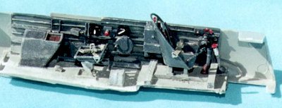 In my references the different marques show an increase in
the amount of armour afforded the pilot, being placed on a roll over structure
behind the pilot’s seat. At some undetermined point the armour was increased
from simple plate with two openings, to a complete plate with a circular piece
that could be opened to talk with the rear gunner. I elected to use the Aires
kit roll over bar that has no armour. The roll over bar is a fairly tight fit
against the canopy.
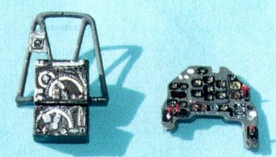 The entire cockpit is painted in Model Master
RLM02, Grau and RLM66, Dunkelgrau. The RLM02 is painted on most of the larger
flat areas of the cockpit, such as the floor and walls and internal structures
of the canopy, whilst the RLM66 is painted on the raised ribs and instrument
panels. Again, there is some question as to the timing that the cockpit interior
colour changed from RLM02 to RLM66. I can find no reference for the Stuka and
elected to follow the kit instructions, albeit to use RLM66 with some artistic license. The gauges are picked out in flat black and have a small amount of Testors
Clear Glue to simulate the glass. Some of the instrument dials also have a
colour band depending on their function, i.e., blue for oxygen, brown for oil
and yellow for fuel. Throttle and other critical levers are painted in red.
There are two oxygen bottles with the kit, painted RLM25, blue and these are surrounded by photo etch to represent the storage containers.
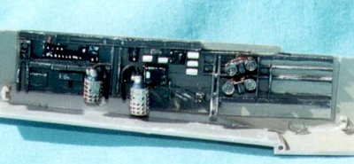 Once the cockpit walls were installed in the fuselage halves
the completed floor was installed only to find that it was in need of sanding to
fit. This was achieved using the Dremel tool. The fine dust that came from the
operation was allowed to stay on the model and it simulates the amount of sand
that one would expect in the cockpit of such a desert operator.
Now a word of caution to people of minds like my own,
sometimes too fast for their own good, or perhaps too eager to bother with the
instruction sheet in my case! I had removed the forward bulkhead of the fuselage
in preparation for the resin engine compartment bulkhead. I had completed
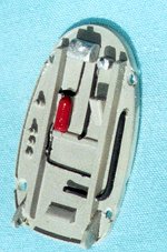 painting this, RLM02, and used superglue for attachment. All was going well
until I discovered that I had left off the clear part that serves to give the
pilot his view of the target. This resulted in the cutting away of the resin
bulkhead and carefully fitting of the clear bit, followed by the reattachment of
the engine bulkhead! Remember to RTFM!
The Fuselage and Wings
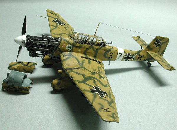
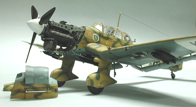
Having decided to build the Aires engine and attach it to the fuselage I set about checking the engine cowling for fit. Unfortunately the engine, when mounted on the frame, does not allow for the cowls to attach with any degree of fit. It appears that the length of the engine is simply too long for the cowl. I attempted to correct this by cutting the engine mounting frames to shorten the unit, but with all the added bits and the degree of difficulty increasing with time, elected to simply display the model without cowls as if it was undergoing maintenance. This will now involve some diorama work to display the finished model. Oh well!
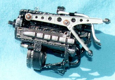 The cowls were cut to represent how the individual panels
would be removed during the maintenance and were painted RLM02 on the inside and
matched to the remaining airframe on the outside. The panels were also thinned
to better represent the true panel thickness. As I have little in the way of
reference material for the inside of these panels I have not put any
strengthening braces on them.
I have some great photos of the Berta without the engine cowls showing the aircraft fully laden for an operation. This was quite a routine and safe practice as the bombs were not fused until the actual flight and it was a common sight around the airfield to see a stack of inert bombs waiting to be loaded onto the various aircraft.
With the wings I elected to do a little kit bashing and immediately separated the flaps and ailerons from the main wing. This was to correctly depict the actuating rods from the main span to the flaps and ailerons. The kit shows this as a solid piece of plastic. I also removed the rudder and tail surfaces to give the model some dynamics. In the latter this also involved partially cutting through the panel line and then slightly bending the elevator. The trim tabs were similarly treated and bent in the opposite direction.
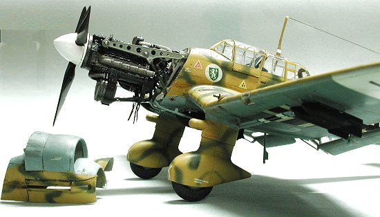 I had read a review of an aircraft recently where the trim
tabs had also been removed and repositioned to more accurately depict the
control surfaces. I liked the idea and decided to give it a try here. Note that
the trim tabs are positioned opposite to the direction of the elevators and
rudder, being confirmed by an aircraft engineer in the original article.
I decided that I would connect the lower wing surface to the two upper surfaces prior to gluing the wing to the fuselage. This was done after some test fitting, all the while wishing for another hand to hold the fuselage halves together long enough to check the gaps. It would have been easier to use tape in retrospect.
The various ailerons and flaps were reattached after the surgery. The brass actuating rods were added after the whole thing had been painted.
Undercarriage
As the Stuka has fixed undercarriage it was relatively straightforward to make the units and glue them on after painting the undersurfaces of the wings. The spats that cover the main wheels are the same colour as the upper surfaces and it is easier to do the job whilst they are not joined.
The instructions call for the interior of the spats to be black. I elected to paint them with Model Master RLM 02, Grau as I feel that most inner surfaces were painted in this colour and the spats would have been similarly coated. Besides the inner surfaces are almost invisible when on the model.
|
PAINT & DECALS |
The two versions in this kit have a similar paint scheme, as you would expect operating in the same arena of conflict. One has fairly large blotches of olive green over sandgelb (yellow), 3. /STG1, and the other has small squiggles over the sandgelb, 1. /STG3. I elected to do the latter as I wanted an aircraft that was predominantly yellow in colour. The undersurface of both aircraft is RLM78, Hellblau. The aircraft from 1. /STG3 also has a white theatre band on the fuselage and both underside wingtips.
I first did some pre-shading by hand painting the panel lines with Flat Black. This was allowed to dry for a few days while other chores were completed. I then painted the entire lower surface of the model in RLM78 and, once this was dry painted the upper surfaces in Model Master RLM79, Sandgelb. I had previously masked off the clear cockpit glazing with Tamiya Masking tape and attached the non movable front windshield and middle cockpit glazing. I had also painted the unmasked areas of the glazing with RLM02.
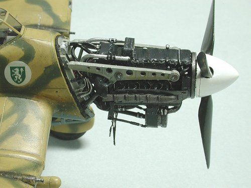 The instruction sheet, yes I do sometimes use them, also
calls out for some decals to be put on the inside of three of the four part
cockpit. I decided to do away with them in preference to fine copper wire,
painted RLM02, and attached to the inside in place of the decals. I also managed
to avoid fogging the plastic with the superglue, well almost.
The squiggle pattern used on this aircraft was Model Master RLM83, Olivgrun and was freehand sprayed. The problem with this approach is that the over-spray can be quite heavy and cover the lower colour. There are two ways of solving the problem, one is to simply generate a mask and simply spray, and the second is to use a simple polish to lightly rub off the over-spray. I chose the second method using Tamiya Polishing Crème. The final effect is one of gradational paint for the squiggles and doesn’t look too out of whack.
As I had been having a few problems with the engine and engine cover fit I had removed the engine from the bearers and temporarily attached the covers to the nose of the fuselage. Masking was done for the painting of the Sandgelb and the assembly was still attached for the squiggle pattern to maintain continuity across the aircraft surface. It probably won’t be that visible once the diorama is completed, but judges are a fickle lot, aren’t they?
 Once the paint had dried and I had used the polish to clean
up the over-spray I found an added bonus in that the paint surface was now very
shiny and clear of minor blemishes. So good was this surface that the decals
were applied without any clear gloss coat and without them silvering.
The whole airframe was then sprayed with Humbrol Flat Kote and weathered with Artist watercolours. As this aircraft operated under desert conditions the weathering colours were not the normal dark browns and blacks but rather ochre and a couple of blends of pink with some darker tones, simulating fine sand, mixed with dark browns around the engine and exhausts. Paint chipping was simulated with Tamiya XF16, Flat Aluminium. The final coating was again Humbrol Flat Kote to seal the whole kit.
I then set about attaching the wheels and small fiddly bits that always snap off when you least expect it to happen. This was especially true with the flaps and ailerons that seemed to fall off every time I looked sideways at the model. They were attached after all other bits went on the aircraft, after about five re-attachments throughout the building!
The final bits to go on the airframe were the cockpits glazing and the aerial wire, where I use invisible thread and paint it black (sounds like a good name for a song) or silver depending on my moods. In this case I must have been into heavy metal because it ended up being painted Gunze Sangyo Steel.
Oh by the way, leave the aerial off until the last moment as I managed to snap it off almost as many times as the flaps. It will never be the same and will be replaced before the diorama is completed.
|
CONCLUSIONS |
This is the first review where I have been fortunate enough to have another photographer shoot my models. In this case Neil Royes, a member of the Queensland IPMS branch, took a number of photos using his digital Nikon. The shots have made the model appear much better than I would have thought, proving the adage that the camera tells lies. I am very grateful for his help and hope that my next effort will receive a similar treatment, or else I may have to lift my game in the photography stakes!
I thoroughly enjoyed building this aircraft not only because it went together well and is a famous plane, but also because it was a challenge to get all the bits working together to produce the final article. As I had problems with the engine and the kit cowling panels it caused me to go into an area previously avoided – the dreaded diorama.
Now I haven’t gone to any trouble to show the model in the diorama, but once it is completed I will forward some shots to round out the article.
I can recommend this model for any category of modeller, straight out of the box, or accessorized to the max. If you choose to do the Aires upgrade simply be aware that you may need to cannibalize the engine firewall more than is initially apparent. I had at least three attempts to get the flaming thing to fit and ended up going the whole hog and building a diorama to depict my ineptitude at making everything fit.
Still it is a great model and one that is unusual in my collection where most are from the Pacific and European theatres.
Go on, get out there and buy one and take it home and build it! I promise you’ll have a ball!
|
REFERENCES |
Stuka! Junkers Ju-87, by
Copyright ModelingMadness.com
Thanks to Neil Royes of the Queensland IPMS branch for photos of the completed model
If you would like your product reviewed fairly and fairly quickly, please contact the editor or see other details in the Note to Contributors.