PCM 1/32 FW-190A-3
| KIT #: | 32011 |
| PRICE: | $55.00 SRP |
| DECALS: | Eight option |
| REVIEWER: | John Summerford |
| NOTES: | Karaya decal set D3207 |
| HISTORY |
When the Fw-190 entered combat in August 1941, it proved superior to the Spitfire and Hurricane up to medium altitude. The A-3 variant featured four 20 mm cannons in the wings to go along with the pair of 7.92 machine guns in the nose.
| THE KIT |
 Four hard, gray plastic sprues are
sealed in zip top bag with the clear, resin, and color photo-etch parts in
separate bags. The decals are ensconced in the instruction booklet.
Four hard, gray plastic sprues are
sealed in zip top bag with the clear, resin, and color photo-etch parts in
separate bags. The decals are ensconced in the instruction booklet.
Three building options are provided, either A-0 or A-1/-2, or -3. Most of the differences are between the -0 version and the others and the instructions are clear as to which parts to use. Total parts count is, 117.
Assembly instructions are printed on eight pages of glossy paper, include a color chart, parts map and extend over 25 steps. Color call-outs are for RLM colors or generic hues. A separate painting and decaling guide in color is included.
| CONSTRUCTION |
Step one calls for building up the seat. The final step is when it’s installed, so I decided to wait for later since I dislike having sub-assemblies sitting around. I also had on order the paint needed for the cockpit when I started, so began the build with wings.
The wheel well is a resin insert and the leg portion is built up Both wings had a warp in span, creating a gull wing affect, so a piece of basswood was clamped to the wings as the glue set to keep them straight.
 Turning to the inside face of the
fuselage halves, vent backing plates and resin exhaust stubs were glued in
place, followed by the tail wheel well. By now the paint on order had arrived,
so the cockpit sides and tub were sprayed RLM 66. After taping the fuselage
halves together, I was able to determine that the tub could be inserted from
below. That was a good thing because the fuselage halves were also warped. The
engine was assembled and glued into one side. Starting at the tail, the halves
were glued together, then the cockpit opening lined up and liquid cement applied
to the inside of the seams.
Turning to the inside face of the
fuselage halves, vent backing plates and resin exhaust stubs were glued in
place, followed by the tail wheel well. By now the paint on order had arrived,
so the cockpit sides and tub were sprayed RLM 66. After taping the fuselage
halves together, I was able to determine that the tub could be inserted from
below. That was a good thing because the fuselage halves were also warped. The
engine was assembled and glued into one side. Starting at the tail, the halves
were glued together, then the cockpit opening lined up and liquid cement applied
to the inside of the seams.
While that was setting up, the photo-etch instrument panel was glued together. I’ll indulge in a rant aimed at the photo-etch producers here: It’s great that detail like levers and knobs can be added to the faces of panels, but can you please create a mounting hole for each of those parts? I tried to drill openings for the levers to hold a drop of glue and ruined two drill bits. I decided to forego the levers. The tub was detailed and the instrument panel, minus the gun sight, was mated to the tub and that assembly dropped into place after a bit of filing.
After aligning the nose, more
liquid cement was applied. The access panels for the nose guns and engine were
filed down and glued in place. The bottom en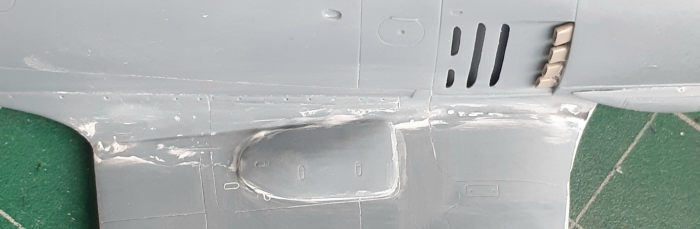 gine access panel must be glued in
place after the wings are mated with the fuselage, so the wings came next. I was
not surprised to find both a gap and a step on both sides. A couple of clamps
were used to get the best alignment possible and super glue was used to attach
the wings to the fuselage and act as filler.
gine access panel must be glued in
place after the wings are mated with the fuselage, so the wings came next. I was
not surprised to find both a gap and a step on both sides. A couple of clamps
were used to get the best alignment possible and super glue was used to attach
the wings to the fuselage and act as filler.
A couple of sessions of filling and sanding the joins followed, obliterating a lot of surface detail. Here I was more lucky than skilled. I forgot to add the bulges for the inboard cannon breaches when I built the wings, so adding them at this point restored most of the lost detail. The bottom engine access panel and the two-part nose ring (fore and aft, not top and bottom or left and right) were installed and the seams in the nose cleaned up.
The horizontal tail was attached next via butt joints and the seams filled and sanded. The instructions call for adding deck behind the seat in the last step. Because it has the same color as the fuselage in my paint scheme, I chose to add it at this point. It would have been much easier to and trap it in place on the locating tabs when the halves were coming together. I’m mystified why it’s added at the end of the build. The prop was assembled next and with that done, it was ready for paint.
| COLORS & MARKINGS |
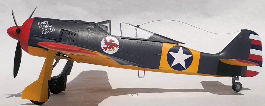
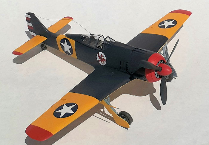
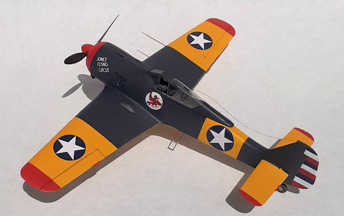
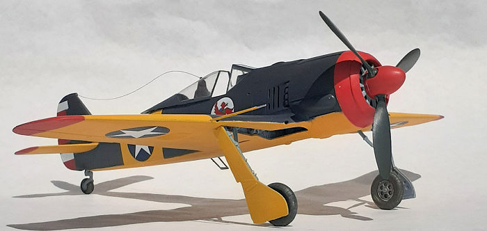
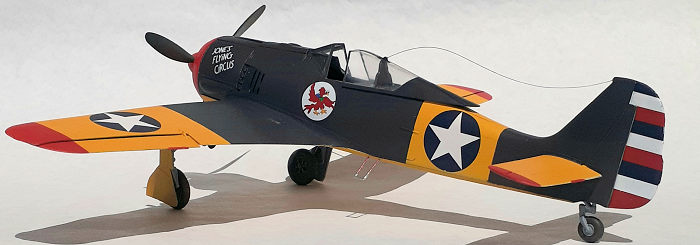 I thought It would be fun to do an unusual paint scheme
and decided to model a captured plane. This scheme represents a plane used as a
hack for 65th fighter Squadron of the 57th fighter group.
I think this was during 1943 when the group was stationed in north Africa.
I thought It would be fun to do an unusual paint scheme
and decided to model a captured plane. This scheme represents a plane used as a
hack for 65th fighter Squadron of the 57th fighter group.
I think this was during 1943 when the group was stationed in north Africa.
I tried MRP paints for the first time to see how well they work. The model was given a coat rattle can auto primer, then the yellow and red portions were sprayed with MRP sand yellow primer. I’m surprised at how effective the tinted primer worked for those colors. The fuselage and inner wings were painted with RLM 66 mixed with Alclad clear blue. The MRP paints resulted in nice finish and I’m sure I’ll buy more.
The Karaya decals behaved well with one exception. I’ve never encountered ink flaking off of a decal before, but a small bit did on the top blue rudder stripe. The rudder decals are printed as rectangles, so I gave them a rough trimming before applying them. This gave me some scrap to lay over the flaked area. A clear coat of satin finish was sprayed on.
| FINAL CONSTRUCTION |
 The tail wheel was installed
followed by the main gear. A more definitive mounting point for the main legs
could have been supplied to ensure the correct angel. I’m not sure if I have it
right. Holes were drilled for the foot step and that was glued in place.
The tail wheel was installed
followed by the main gear. A more definitive mounting point for the main legs
could have been supplied to ensure the correct angel. I’m not sure if I have it
right. Holes were drilled for the foot step and that was glued in place.
Turning back to the first step, the seat was built and installed. Windshield and canopy came next. I chose to have the canopy opened so I wouldn’t have to worry about getting the radio aerial tight. I used .010 monofilament line for the aerial. It has been on the spool for so long that it retained a coil shape. I tried to get it to relax some by running an extinguished matchhead along a taught length. That helped some, but I couldn’t get it to drape naturally when I glued it in place.
All that was left was the pitot and prop assembly and the model was done.
| CONCLUSIONS |
I lost my enthusiasm for this build when the wings were mated to the fuselage and became tired of fighting the model. Fit of the parts were a battle to end. I’m loathe to give up on a project however, so I saw it to the finish. Aside from the usual glue, files. knives, putty, and sandpaper, a variety of clamps and a lot of patience is required to complete this model. The project should have been completed sooner than the 26 hours spent on it.
4 October 2021 Copyright ModelingMadness.com. All rights reserved. No
reproduction in part or in whole without express permission. If you would like your product reviewed fairly and fairly quickly, please contact the editor or see other details in the
Note to
Contributors.