Fine Molds 1/48 Kikka
| KIT #: | FB 10 |
| PRICE: | 2600 yen |
| DECALS: | One option |
| REVIEWER: | Ben Brown |
| NOTES: |
| HISTORY |
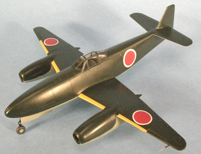
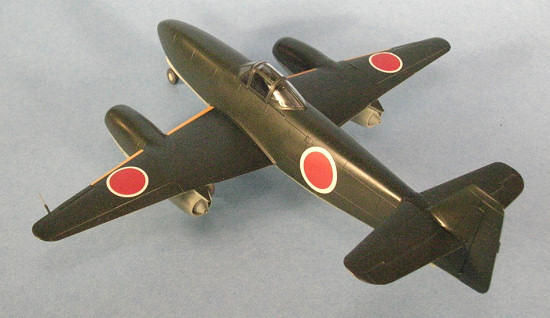
Looking like a small Me-262, the Nakajima Kikka (Orange Blossom) was the only jet to fly in Japan during WWII. It would be easy to dismiss the Kikka as a primitive copy of its German cousin, but the aircraft and its engines were original Japanese designs.
Japanese studies in jet propulsion began as early as 1920. During the late
1930s, Rear Admiral Hanajima conducted experiments with both rocket engines and
ram jets, but the data was never put to much use. Also during the late ‘30s,
Captain Tanegashima of the Kaigun Koku-sho (Kugisho) at Yokosuka was given the
go-ahead experiment on jet propulsion. His studies mainly centered around a
turbo-prop engine. When word of Germany’s successful flight of the He-178
reached Japan in 1942, several stagnant
 projects were reopened. One of these
was a hybrid jet engine with the compressor driven by a piston engine. This
type of engine was flown on Italy’s Campini and was later used on the Okha Model
22 piloted suicide bomb. The Japanese realized that the pure jet offered the
best performance potential, and in 1943 tested the TR-10 (Turbo-Rocket), which
had a single centrifugal compressor and a single turbine. Centrifugal
compressor engines are not very efficient and operate at a very high engine
RPM. The engine was developed further, with four axial-flow compressor stages
added in front of the centrifugal compressor to reduce the operating RPM of the
engine and increase thrust. The new engine was designated Ne-12 (“Ne” stands
for “Nensho Rocketto” or “Burning Rocket”). This new engine was too heavy to be
used in an aircraft, so after further development, the Ne-12B was built. The
new engine weighed 770 pounds and was the one originally intended to power the
Kikka.
projects were reopened. One of these
was a hybrid jet engine with the compressor driven by a piston engine. This
type of engine was flown on Italy’s Campini and was later used on the Okha Model
22 piloted suicide bomb. The Japanese realized that the pure jet offered the
best performance potential, and in 1943 tested the TR-10 (Turbo-Rocket), which
had a single centrifugal compressor and a single turbine. Centrifugal
compressor engines are not very efficient and operate at a very high engine
RPM. The engine was developed further, with four axial-flow compressor stages
added in front of the centrifugal compressor to reduce the operating RPM of the
engine and increase thrust. The new engine was designated Ne-12 (“Ne” stands
for “Nensho Rocketto” or “Burning Rocket”). This new engine was too heavy to be
used in an aircraft, so after further development, the Ne-12B was built. The
new engine weighed 770 pounds and was the one originally intended to power the
Kikka.
During 1944, the Germans sent the Japanese a full set of blueprints for their jet engines. An engineer returning to Japan on the IJN submarine I-29 with the blueprints apparently decided that after 87 days at sea, he would get off the boat at Singapore and fly home. Can’t really blame him. He left the blueprints on board the sub, carrying only a general design drawing of the BMW-003 with him. The I-29 was later sunk off the coast of Manila, so the Japanese had to make do without any German engine design data. One can almost imagine the scene in the poor engineer’s boss’s office: “You left the &^%$% drawings on the &^%$% boat??!!!”
The BMW-003 engine used an eight-stage axial flow compressor section which
operated at a lower RPM than an engine with a centrifugal compressor. The
Japanese engineers also went with an axial flow compressor section for their new
engine, designated Ne-20, which was first run on March 26, 1945. The Ne-20
looked similar to the BMW-003, but it was only about ¾ the size of the German
engine. Like their German counterparts, the Japanese suffered from supply
problems due to Allied bombing, so they lacked many materials critical to
manufacturing jet engines. Because of this, the average lifespan of the Ne-20
engine was about five hours. These engines produced about 900-1000 lbs of
thrust, which would have pushed the little Kikka along at up to
 376 knots when
clean, or 275 knots while carrying a 500 kg bomb. A US Navy report on the
engines states “the Ne-20 appears to be a fairly well and simply designed
turbojet. The BMW-003 was probably the best of the smaller German turbojets and
the Japanese apparently didn’t sacrifice any of the 003’s good features.”
376 knots when
clean, or 275 knots while carrying a 500 kg bomb. A US Navy report on the
engines states “the Ne-20 appears to be a fairly well and simply designed
turbojet. The BMW-003 was probably the best of the smaller German turbojets and
the Japanese apparently didn’t sacrifice any of the 003’s good features.”
Originally planned as a Special Attack aircraft (usually this means suicide missions), Japanese Navy planners apparently soon realized that this type of aircraft would be too precious to send on one-way missions. As the design progressed, the Kikka’s mission changed to that of a bomber, with weapons to be carried on pylons just aft of the nose gear, the same configuration used on the Me-262. Later versions were to include a two-seat reconnaissance model and a fighter version armed with two 30mm cannon. Some thought was also given to the survival of the pilot and aircraft. Production models were to be fitted with shatterproof glass, armored windscreen, armor plate around the pilot, and an automatic fire suppression system for the fuel tanks. By the day of the Kikka’s first flight, 25 airframes were already in production, including five two-seat trainers.
The Kikka had a wing span of 39 ft 9 11/16 in and was 26 ft 7 7/8 in long. In comparison, the Me-262 had a 40 ft 11 ½ in wing span and was 34 ft 9 ½ in long. In order to make the jet easier to hide in underground hangars, it was equipped with folding wings. Provision for Rocket Assist Take Off (RATO) units was made to help a fully loaded Kikka get off the ground.
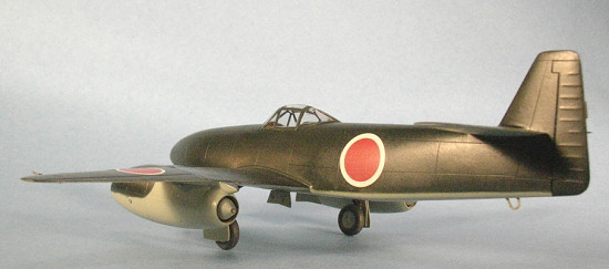
Sheet steel was widely used in the Kikka’s construction, since there was a shortage of Duralumin. The elevators, rudder, and ailerons were fabric-covered. The Kikka was only the second aircraft the Japanese had built with a tricycle landing gear. The main landing gear was adapted from the Zero fighter and the nose wheel was lifted from the P1Y Ginga (Frances) bomber.
The first Kikka was completed on June 25, 1945. It was eventually trucked to
Kisarazu Air Base for its first flight. On July 14th, the Japanese
learned of a new aviation hazard: FOD (Foreign Object Damage), when a loose bolt
was sucked into the intake of one of the engines during ground testing. The
bolt destroyed the compressor blades, requiring and engine change . The engine
was replaced amid frequent air attacks, and taxi checks were made on July 27.
High-speed taxi checks showed the brakes were not very effective. By August 7,
the jet was ready for its first flight. Lt. Commander Takaoka started the Kikka
and taxied to the end of the runway. The jet was only partially fueled in order
to keep its weight down, so the RATO units were not installed for this first
flight. Initial acceleration was slow, but built rapidly as the jet rolled down
the runway. Takaoka’s comments to author Robert Mikesh about the experience
echoed those made by German ace Gen. Adolph Galland after his first flight in
the Me-262. “It was difficult to believe that there was no propeller pulling
me. There had to be one on each side – turning so rapidly that I could not make
out the usual blurred propeller disc. But it was true, these were pure jet
engines, and they were propelling me with greater performance than I had ever
experienced before.” “The lack of noise and engine vibration was something I
was not prepared for.” 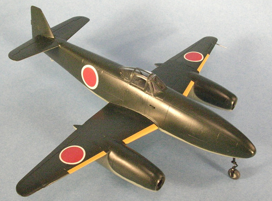 After flying over Tokyo Bay for eleven minutes, it was
time to land. Like other early jet engines, the Ne-20s were very sensitive to
throttle changes, and Takaoka had to be careful not to cause a flame-out when
reducing power for landing.
After flying over Tokyo Bay for eleven minutes, it was
time to land. Like other early jet engines, the Ne-20s were very sensitive to
throttle changes, and Takaoka had to be careful not to cause a flame-out when
reducing power for landing.
The next fight was scheduled for August 10. This time, more fuel would be carried and the RATO units would be installed. Takaoka was uncomfortable with the angle the RATO units were mounted to the jet, so their thrust reduced from 800 kg to 400 kg. US Navy fighters were in the area on the 10th, so the second flight was postponed until the 11th. Takaoka taxied to the end of the runway, spooled up the engines, and ignited the RATO units. Unfortunately, his uneasiness about them proved correct. Their thrust angle forced the nose down and prevented him from rotating for takeoff. He aborted the take off, but ran out of runway before he could get the jet stopped. The plane skipped across a drainage ditch, taking the landing gear off, and finally came to a rest in the sand at the edge of Tokyo Bay. Thus ended Japan’s jet program.
After the war, airframes 3, 4, and 5 (and possibly other partial airframes) were brought to the US for study. Today, only a single example survives in the National Air and Space Museum.
Like their German counterparts did with the Me-262, Ar-234, and He-162, the Japanese pinned their hopes on this new “super weapon,” but, the Kikka (and it’s sister, the larger Me-262-like Nakajima Ki-201 Karyu) would have done very little to hold back the waves of Allied aircraft attacking their homeland.
| THE KIT |
In the box, Fine Molds’ Kikka looks like it came from Hasegawa. There are only 63 parts molded in light grey plastic, with a clear sprue containing the one-piece canopy. A nut and bolt are provided for nose weight and they fit into a cradle built into a deck in the nose. The cockpit parts are simple, but busy enough to look good under the thick, one-piece canopy. This particular release of the kit has no provision to display an engine, but a limited edition version of the kit (costing around $45US) included a white metal and resin engine. The decal sheet includes national insignia, wing walkway markings, and instruments to lay over the instrument panel. The kit instructions show additional tail codes and a data panel for a hypothetical operational jet, but these are not included on the decal sheet.
| CONSTRUCTION |
 As I mentioned
earlier, sitting in the box, this kit looks like it could have come from
Hasegawa and would make a great weekend project. Once construction starts, it’s
obvious Hasegawa never touched this one. It’s a step up from the typical
limited-run kit, but doesn’t have the “shake the box” quality of the newer
Hasegawa and Tamiya kits.
As I mentioned
earlier, sitting in the box, this kit looks like it could have come from
Hasegawa and would make a great weekend project. Once construction starts, it’s
obvious Hasegawa never touched this one. It’s a step up from the typical
limited-run kit, but doesn’t have the “shake the box” quality of the newer
Hasegawa and Tamiya kits.
I began by building the cockpit per the instructions. I painted everything Tamiya IJN Green, with details picked out in black. By late war, Nakajima was often painting the cockpits of their planes the same color as the exteriors to save time and resources. Typical of most Japanese model companies, Fine Molds has molded the seat without seat belts, so I added a lap belt made from tape. I glued the nut and bolt assembly into it’s cradle in the nose, and added a fishing sinker just to be 100% sure the model would stay on all three tires. With so few cockpit parts to assemble, things proceeded quickly. “I’ll have this baby ready to paint in a couple of hours,” I thought happily.
The cockpit fit inside the fuselage without any trouble, but the two fuselage halves were another matter. Part of the problem was the nose gear well threw everything out of alignment, but even after that was taken care of, the two fuselage halves just would not match up. After much swearing, adjusting, sanding, and swearing, I finally got the two halves almost aligned. Sandpaper and filler would have to fix the rest. There were a couple of sink holes on the sides of the fuselage, corresponding with some details molded into the cockpit interior. These were filled with Mr. Surfacer and sanded smooth.
 The wings actually fit together very well. When I added them to the fuselage,
I had trouble getting a smooth transition between the wing and fuselage on the
belly of the model, especially just forward of the wing. I think part of that
was Operator Error. The engine nacelles required more swearing, sanding,
shaping, and swearing. The front and rear sections were a different diameter
than the center sections of the cowlings. When the engines were glued to the
wings, there was a large gap between both nacelles and the wing on the inboard
sides. These gaps were large enough that I resorted to using styrene strip to
fill them. On a positive note, the horizontal stabilizers and the parts that
make up the wing slots fit great! I spent some time sanding and polishing the
model, then rescribed the multitude of panel lines that had been removed or
covered with putty. Finally, the Kikka was ready for paint!
The wings actually fit together very well. When I added them to the fuselage,
I had trouble getting a smooth transition between the wing and fuselage on the
belly of the model, especially just forward of the wing. I think part of that
was Operator Error. The engine nacelles required more swearing, sanding,
shaping, and swearing. The front and rear sections were a different diameter
than the center sections of the cowlings. When the engines were glued to the
wings, there was a large gap between both nacelles and the wing on the inboard
sides. These gaps were large enough that I resorted to using styrene strip to
fill them. On a positive note, the horizontal stabilizers and the parts that
make up the wing slots fit great! I spent some time sanding and polishing the
model, then rescribed the multitude of panel lines that had been removed or
covered with putty. Finally, the Kikka was ready for paint!
| COLORS & MARKINGS |
 Fine Molds’
latest issue of the Kikka includes a set of canopy masks from Eduard. This was
the first time I had used their masks and found them to be easy to apply. I
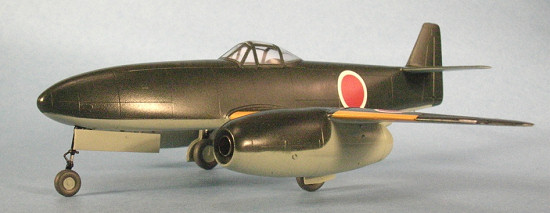
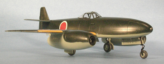
painted the undersides of the Kikka Tamiya IJN Grey, then sprayed the topside
with Tamiya IJN Green. The instructions indicate you have a choice between grey
or natural metal undersurfaces, but the photo on the cover of Monogram Close-Up
#19 clearly shows grey paint peeling off of one of the engine nacelles due to
heat from the engine. The yellow ID bands on the wing leading edges were masked
and painted them with Gunze Orange/Yellow. I then gave the model a coat of
Future, and applied the kit decals. These were limited to the six national
insignia. I had to leave the walkways off because the red was printed over a
white background and was badly out of register. After another coat of Future
had dried, I sealed everything with Polly S Clear Flat, which turned out
semi-gloss for some reason.
Fine Molds’
latest issue of the Kikka includes a set of canopy masks from Eduard. This was
the first time I had used their masks and found them to be easy to apply. I
painted the undersides of the Kikka Tamiya IJN Grey, then sprayed the topside
with Tamiya IJN Green. The instructions indicate you have a choice between grey
or natural metal undersurfaces, but the photo on the cover of Monogram Close-Up
#19 clearly shows grey paint peeling off of one of the engine nacelles due to
heat from the engine. The yellow ID bands on the wing leading edges were masked
and painted them with Gunze Orange/Yellow. I then gave the model a coat of
Future, and applied the kit decals. These were limited to the six national
insignia. I had to leave the walkways off because the red was printed over a
white background and was badly out of register. After another coat of Future
had dried, I sealed everything with Polly S Clear Flat, which turned out
semi-gloss for some reason.
| FINAL CONSTRUCTION |
There wasn’t a
whole lot of final assembling to do. Just add the landing gear, tail bumper,
and pitot tube. I left the RATO units off of my model, since they were not
used on the jet’s first flight, and I felt like they take away from the Kikka’s
clean lines. The Kikka didn’t have its nose gear door fitted for its first
flight, but I glued it on my model because it looked strange without it.
Besides, maybe they put it on before the second flight!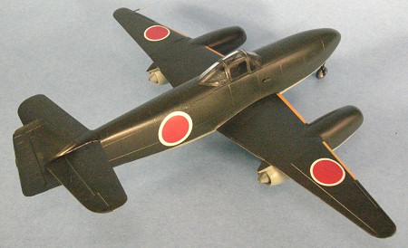
| CONCLUSIONS |
Had this kit been produced by Hasegawa or Tamiya, it would have been a one-afternoon slammer. Fine Molds’ Kikka is definitely not for beginners or for people with a deficit of patience. There is not a lot of detail, but it still builds into a very nice-looking model of a rare bird. Recommended, but have plenty of putty and sandpaper handy!
| REFERENCES |
Monogram Close-Up #19 Kikka, Robert Mikesh, Monogram Aviation Publications
Hikoki 1946 http://www.j-aircraft.org/xplanes/
June 2006
Copyright ModelingMadness.com. All rights reserved. No reproduction in part or in whole without express permission.
If you would like your product reviewed fairly and fairly quickly, please contact the editor or see other details in the Note to Contributors.