|
KIT: |
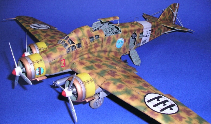
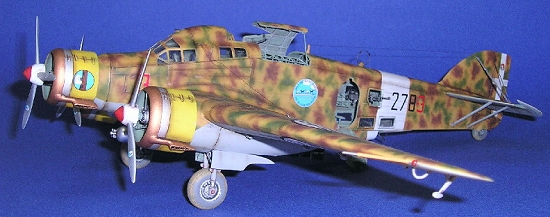
Trumpeter 1/48 Sovoia-Marchetti SM-79 II Sparviero |
|
KIT # |
2817 |
|
PRICE: |
SGD 50.00 |
|
DECALS: |
One aircraft |
|
REVIEWER: |
|
|
NOTES: |
Eduard SM-79 Internal and Exterior Photo-etched Detail Sets Used, Sky Models (sheet no: 48-018) decals used. |
|
HISTORY |
The history of this aircraft has been adequately covered in this website (and many others), so I shall not bore you readers with yet another repeat.
|
THE KIT |
A preview of this kit can also be found in this website. I would like to add that initial impressions of the moldings were quite crisp although cockpit details are sparse. Sidewall details in the cockpit area are totally non-existent and the ribbing detail in the cabin area was marred by numerous ejection pin marks. The representation of the fabric covered areas of the fuselage and tail surfaces are rather exaggerated. Wheel wells details are also lacking.
|
CONSTRUCTION |
WINGS
I departed from the usual
practice of starting off with the cockpit; I proceeded with the wings
instead. Fit was generally good with the exception of the leading edge
slats. The modeler is given the option of posing the latter in either the
stowed or deployed position. Since my references indicate that the slats
were usually stowed when the aircraft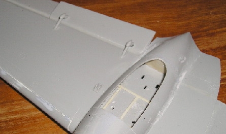 was parked, I elected to represent
this by fitting the slats in their stowed position. This was when I
discovered that the fit was far from perfect. Generous quantities of Milliput epoxy putty were used to fill any offending gaps. Once set, the
Milliput was sanded down and lost panel details were restored with my
trusty scriber. The nacelles were fitted with wheel bay details added
with plastic strip. The front and rear of each wheel well was blanked
off with 30 thou plastic card. Ailerons were fixed in the neutral
position while the flaps were positioned slightly drooped.
was parked, I elected to represent
this by fitting the slats in their stowed position. This was when I
discovered that the fit was far from perfect. Generous quantities of Milliput epoxy putty were used to fill any offending gaps. Once set, the
Milliput was sanded down and lost panel details were restored with my
trusty scriber. The nacelles were fitted with wheel bay details added
with plastic strip. The front and rear of each wheel well was blanked
off with 30 thou plastic card. Ailerons were fixed in the neutral
position while the flaps were positioned slightly drooped.
FUSELAGE AND INTERIOR DETAILS
My next task was to remove
all the internal molded framing in the fuselage sides. I suppose that if
one chooses to build the model as intended by Trumpeter, i.e. with the
clamp shell dorsal opening closed and the port door closed then the
original detail (or lack of it) can be lived with since not much will be
visible anyway. As I chose from the onset to display the innards of this
model, serious detailing work awaited me. However before brandishing my X-acto
Number 12 blade and 150 grit sandpaper, I transferred the framing detail on
paper by gently rubbing a 2B pencil over appropriately sized typing paper
to get the imprint of this detail
 .
I then scraped away the raised detail with the Number 12 blade and removed
any remnants with 150 grit sandpaper. Ejector pin marks that were too
deeply etched were filled with plastic putty and a further sanding with 230
grit sandpaper ensured that everything was nice and smooth.
.
I then scraped away the raised detail with the Number 12 blade and removed
any remnants with 150 grit sandpaper. Ejector pin marks that were too
deeply etched were filled with plastic putty and a further sanding with 230
grit sandpaper ensured that everything was nice and smooth.
The fuselage framing
detail was restored with 20 by 30 thou plastic strips; I used th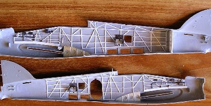 e
impressions which I prepared earlier as a reference together with a set of vernier calipers to ensure that everything lined up and was symmetrical. I
elected not to use Eduard’s photo-etched cockpit sidewall details for the
framing as I felt that they were too flat and might not show up well after
painting and dry brushing. Therefore I used these as patterns and
fashioned the details in a similar pattern as the fuselage cabin framing.
Cables, wiring and wiring harnesses were fashioned from copper wire and
lead foil respectively.
e
impressions which I prepared earlier as a reference together with a set of vernier calipers to ensure that everything lined up and was symmetrical. I
elected not to use Eduard’s photo-etched cockpit sidewall details for the
framing as I felt that they were too flat and might not show up well after
painting and dry brushing. Therefore I used these as patterns and
fashioned the details in a similar pattern as the fuselage cabin framing.
Cables, wiring and wiring harnesses were fashioned from copper wire and
lead foil respectively.
COCKPIT
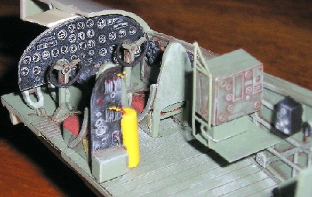
The cockpit floor was assembled with the photo-etched parts per instructions with the exception of the rear bulkhead where the rearward firing machine gun ammo boxes were mounted. I managed to completely botch up these photo-etched parts and had to completely rebuild the bulkhead and ammo boxes from plastic sheet. The results were better than originally expected. The photo-etched seat belts were super-glued to the kit supplied seats without much hassle.
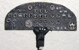 I tackled the instrument
panel next. The detail from the kit supplied instrument panel was sanded
off as the backing mount for the photo-etched panel face and acetate film
representing the individual instruments. The rear of the acetate film was
sprayed white and the photo-etched panel face was primed with industrial
grade acrylic primer from a can. Once the primer had set, I gave the panel
a coat of Testors Flat Black from a can and dry brushed with neutral gray
and white enamels to enhance the details. The acetate film was then
super-glued to the photo-etched panel and the excess acetate film was
trimmed away. This subassembly was then attached to the kit instrument
panel with generous amounts of super-glue.
I tackled the instrument
panel next. The detail from the kit supplied instrument panel was sanded
off as the backing mount for the photo-etched panel face and acetate film
representing the individual instruments. The rear of the acetate film was
sprayed white and the photo-etched panel face was primed with industrial
grade acrylic primer from a can. Once the primer had set, I gave the panel
a coat of Testors Flat Black from a can and dry brushed with neutral gray
and white enamels to enhance the details. The acetate film was then
super-glued to the photo-etched panel and the excess acetate film was
trimmed away. This subassembly was then attached to the kit instrument
panel with generous amounts of super-glue.
BOMB
BAY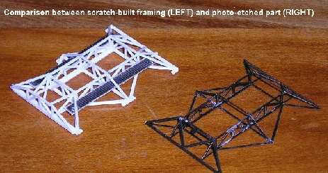
The bomb bay framing was provided as photo-etched parts. Again I chose not to use these as I felt that they did not give the 3-dimensional look especially in this scale, and were over-simplified. Once again, I used the photo-etched parts as patterns and fabricated the complex framing using 25 thou plastic rod and strips, with references gleaned form the web from other modelers’ examples.
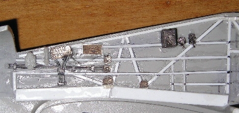 Eduard supplies all
3-dimensional components (throttle quadrants, junction boxes, bomb release
station etc..) as photo-etched parts which had to be folded to shape . I wish they had supplied
these as resin castings but folding up these parts was much easier than
originally envisaged and required only patience, good lighting and a firm
pair of tweezers (I did not even have to use my Hold n Fold tool at this
juncture).
Eduard supplies all
3-dimensional components (throttle quadrants, junction boxes, bomb release
station etc..) as photo-etched parts which had to be folded to shape . I wish they had supplied
these as resin castings but folding up these parts was much easier than
originally envisaged and required only patience, good lighting and a firm
pair of tweezers (I did not even have to use my Hold n Fold tool at this
juncture).
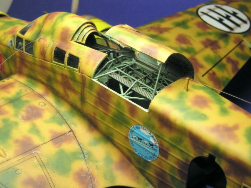
The entire internal portions of the
fuselage, cockpit and bomb aimer’s gondola was sprayed with Testors RAF
Interior Green, a close approximation to Verde Anticorrosione. Some
references indicate that the interior was a light gray shade but I chose to
go with Interior Green instead. Details were accentuated with my usual
concoction of black/brown water colour
 spiked with kitchen cleaner. Once
dry, I removed all excess wash with tissue moistened with kitchen cleaner
and gave a coat of Testors Dullcote Lacquer from a spray can. A highlight
consisting of the base colour lightened with about 30 percent white was
dry-brushed to further bring out the detail. Other details were picked out
with black, white, red and yellow paints as appropriate. Silver was
dry-brushed on high traffic areas to simulate wear and scuffing. Once
done, a further coat of Dullcote was given to seal everything in.
spiked with kitchen cleaner. Once
dry, I removed all excess wash with tissue moistened with kitchen cleaner
and gave a coat of Testors Dullcote Lacquer from a spray can. A highlight
consisting of the base colour lightened with about 30 percent white was
dry-brushed to further bring out the detail. Other details were picked out
with black, white, red and yellow paints as appropriate. Silver was
dry-brushed on high traffic areas to simulate wear and scuffing. Once
done, a further coat of Dullcote was given to seal everything in.
The cockpit floor was then
trial fitted to the starboard fuselage half after first carefully scrapping
away the paint on all contact areas. This was when I noted that the
instrument panel was too wide and prevented the fuselage halves from mating
at the front. I used a No. 10 blade and reduced the thickness of the
fuselage wall where the instrument panel was
 fitted. Despite a rather
substantial reduction of the wall thickness, I still had problems getting
the two halves to meet satisfactorily. I attached the cockpit assembly,
the bomb aimer’s station and tail wheel with super-glue and reinforced the
cockpit assembly with generous applications of super-glue and accelerator.
Before the two fuselage halves were closed, I reinforced the front portion
(just forward to the instrument panel) with scraps of plastic sheet. The
fuselage halves were then fitted together using liquid cement and tapped
together while the glue set.
fitted. Despite a rather
substantial reduction of the wall thickness, I still had problems getting
the two halves to meet satisfactorily. I attached the cockpit assembly,
the bomb aimer’s station and tail wheel with super-glue and reinforced the
cockpit assembly with generous applications of super-glue and accelerator.
Before the two fuselage halves were closed, I reinforced the front portion
(just forward to the instrument panel) with scraps of plastic sheet. The
fuselage halves were then fitted together using liquid cement and tapped
together while the glue set.
The underside of the fuselage from the bomb aimer’s gondola to the rear half of the wing chord was concave. This necessitated generous applications of plastic putty to level the two halves and eliminate the concavity (Pictures do not show the amount of putty used very clearly as the putty is similar in colour to the base plastic, perhaps I should have used Squadron Green Putty for better contrast). All panel lines lost during the sanding process were restored with my trusty scriber.
My next task was to attach
the wings to the fuselage sub assembly. The mating area at the fuselage
was recessed, which meant that the contact area of the wing to the fuselage
was confined to the narrow ridge around fuselage wing root. I figured that
this was not ideal considering the size and weight of the model; handling
by the wings may crack the joint. I proceeded to fill out this area with
20 thou plastic sheet cut to suit the profile of the airfoil section
 . I allowed this to set for a
day before attaching the wings with generous applications of Humbrol liquid
cement. As Trumpeter’s instructions did not indicate the dihedral of the
wings, I referred to Squadron’s S-79 In Action which featured 3 view line
drawings. I supported the wings with Blue Tac as the glue set. I noted
that the joint was far from perfect especially at the trailing edge areas
near the wing fillet and the lower portions, the latter having quite
substantial gaps. As my references indicated that the curve portion
forming the joint line on the lower surfaces of the wings were absent, I
proceeded to fill out these gaps using stretched sprue and generous
quantities of liquid cement. I prefer this technique over the use of
filler for relatively small gaps as this adds strength to the joint and
also makes subsequent scribing easier. What’s more, t
. I allowed this to set for a
day before attaching the wings with generous applications of Humbrol liquid
cement. As Trumpeter’s instructions did not indicate the dihedral of the
wings, I referred to Squadron’s S-79 In Action which featured 3 view line
drawings. I supported the wings with Blue Tac as the glue set. I noted
that the joint was far from perfect especially at the trailing edge areas
near the wing fillet and the lower portions, the latter having quite
substantial gaps. As my references indicated that the curve portion
forming the joint line on the lower surfaces of the wings were absent, I
proceeded to fill out these gaps using stretched sprue and generous
quantities of liquid cement. I prefer this technique over the use of
filler for relatively small gaps as this adds strength to the joint and
also makes subsequent scribing easier. What’s more, t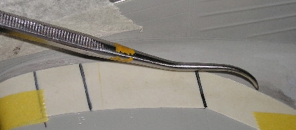 he filler material is
similar to the parent plastic so I do not have to worry about working with
dissimilar materials. Once the plastic had set hard, I used my trusty X-acto
number 12 blade to scrape away the excess material and sanded the areas
with 230 grit paper. All lost panel lines were once again restored with my
scriber. I made a template out of 10 thou plastic sheet and used this to
aid scribing of the curved panel lines at the wing roots .
he filler material is
similar to the parent plastic so I do not have to worry about working with
dissimilar materials. Once the plastic had set hard, I used my trusty X-acto
number 12 blade to scrape away the excess material and sanded the areas
with 230 grit paper. All lost panel lines were once again restored with my
scriber. I made a template out of 10 thou plastic sheet and used this to
aid scribing of the curved panel lines at the wing roots .
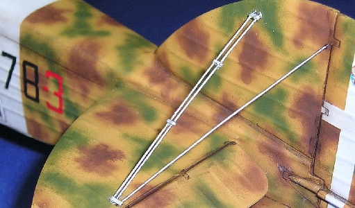
TAILPLANES AND GONDOLA
I now turned my attention
to the tailplanes. For added interest, I elected to glue the elevators in
the down position and checked my references to ascertain the correct droop
angle. I decided not to correct the improperly shaped profile of the
 tailplanes as some other modelers have done since I felt that the effort
was not worth the time and I was satisfied that the overall outline of the
model did not detract from the SM-79 prototype anyway. The support struts
for the tailplanes needed slight trimming to achieve a satisfactory fit and
the locating holes had to be enlarged to accommodate the struts’ location
pins. Once the glue had set, I attached the rudder and offset it slightly
for a more candid appearance. The upper support struts as supplied in the
kit are totally wrong. These were cables on the actual aircraft. As such,
these struts were omitted during the tail plane assembly to be replaced by
steel wire at a latter stage of construction.
tailplanes as some other modelers have done since I felt that the effort
was not worth the time and I was satisfied that the overall outline of the
model did not detract from the SM-79 prototype anyway. The support struts
for the tailplanes needed slight trimming to achieve a satisfactory fit and
the locating holes had to be enlarged to accommodate the struts’ location
pins. Once the glue had set, I attached the rudder and offset it slightly
for a more candid appearance. The upper support struts as supplied in the
kit are totally wrong. These were cables on the actual aircraft. As such,
these struts were omitted during the tail plane assembly to be replaced by
steel wire at a latter stage of construction.
Attaching the bomb aimer’s gondola to the fuselage proceeded without incident except when I test fitted the glazing to this, I found an appreciable gap between the glazing the fuselage underside. To overcome this, I first attached the glazing to the gondola with careful applications of liquid cement and once set, I filled the offending gap with slow setting epoxy applied with a cocktail stick. I used a Q-tip dampened with isopropyl alcohol to remove any excess epoxy before setting the whole assembly aside to allow the epoxy to cure.
CANOPY
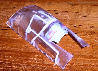 I now focused on the
transparent canopy section. Internal ribbing details were added with
plastic strip, the clear portions were masked and the internal colour was
airbrushed and highlighted.
The forward firing machine gun was fixed and the barrel removed to be
replaced by the photo etched one from Eduard. I expected the rolling of
the photo etched gun barrel to be quite finicky, but this again proved
easier than expected. However, do note that the part should be annealed
over a gas flame before rolling it over a suitably sized rod with the
diameter of the barrel.
Eduard’s instruction sheet indicates that the ring and bead sight is to be
affixed. My references indicated otherwise. All the other flexible
defensive machine guns were also done up at this juncture. I did not quite
like the way the opened dorsal clamp shell hatches were depicted by Eduard
so I cut up the original kit part, thinned down the thickness appropriately
and cemented the various portions in the overlapping manner of the actual
prototype. The entire dorsal assembly was then cemented to the fuselage
sub-assembly. Fit was satisfactory and I only needed some application of
Mr Surfacer 1000 to fill gaps between the windscreen and fuselage. After
this was done, I realized that I had inadvertently missed out the photo
etched ring sight which was to be fitted in the windscreen. There was no
way I was going to rip apart the assembly and decided to live with this
omission. Also, when the barrel of the fixed forward firing machine gun
was installed, it appeared to be too short when compared to references. As
with the previous omission, I did not make any corrections.
I now focused on the
transparent canopy section. Internal ribbing details were added with
plastic strip, the clear portions were masked and the internal colour was
airbrushed and highlighted.
The forward firing machine gun was fixed and the barrel removed to be
replaced by the photo etched one from Eduard. I expected the rolling of
the photo etched gun barrel to be quite finicky, but this again proved
easier than expected. However, do note that the part should be annealed
over a gas flame before rolling it over a suitably sized rod with the
diameter of the barrel.
Eduard’s instruction sheet indicates that the ring and bead sight is to be
affixed. My references indicated otherwise. All the other flexible
defensive machine guns were also done up at this juncture. I did not quite
like the way the opened dorsal clamp shell hatches were depicted by Eduard
so I cut up the original kit part, thinned down the thickness appropriately
and cemented the various portions in the overlapping manner of the actual
prototype. The entire dorsal assembly was then cemented to the fuselage
sub-assembly. Fit was satisfactory and I only needed some application of
Mr Surfacer 1000 to fill gaps between the windscreen and fuselage. After
this was done, I realized that I had inadvertently missed out the photo
etched ring sight which was to be fitted in the windscreen. There was no
way I was going to rip apart the assembly and decided to live with this
omission. Also, when the barrel of the fixed forward firing machine gun
was installed, it appeared to be too short when compared to references. As
with the previous omission, I did not make any corrections.
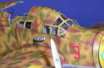
ENGINES AND COWLINGS
Trumpeter depicts an
aircraft with the earlier exhaust arrangement, i.e. all facing the port
side. As I chose to model an
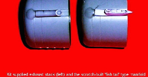 aircraft of a later variant, I had to modify
the starboard cowling so that the exhaust stack faced
aircraft of a later variant, I had to modify
the starboard cowling so that the exhaust stack faced
 outboard. This was
done simply by rescribing the engine access panels. Also since the
aircraft I chose to depict had the later style ‘flattened’ fishtail stacks,
I discarded those supplied in the kit and scratch built three sets from
plastic sheet using the various references I had. According to
my references the cowl opening should be smaller. Again, I chose not to
correct this and went ahead with the kit supplied items.
outboard. This was
done simply by rescribing the engine access panels. Also since the
aircraft I chose to depict had the later style ‘flattened’ fishtail stacks,
I discarded those supplied in the kit and scratch built three sets from
plastic sheet using the various references I had. According to
my references the cowl opening should be smaller. Again, I chose not to
correct this and went ahead with the kit supplied items.
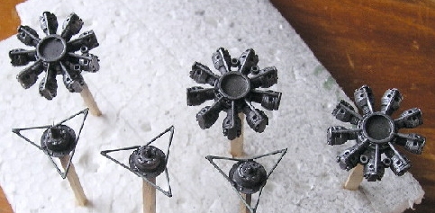
I assembled the engines
per the kit instructions, leaving off the crankcase at this juncture. I
decided not to add the ignition leads as I felt these would not be visible
under the pushrods. However, I added the cowl braces fashioned from
plastic rod. The diameter was carefully measured with a pair of vernier
calipers and the pattern for the braces was transferred on a sheet of
paper. This pattern served as a jig to ensure that the three sets of
braces were correctly and symmetrically lined
 up.
up.
Once assembly of these parts were completed, I sprayed the engines and crankcases with Humbrol Gunmetal and highlighted the details with a dry brushing of sliver. The crankcases were then glued to the engines and the subassemblies set aside.
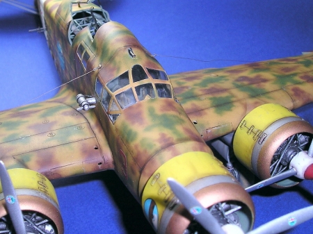
UNDERCARRIAGE
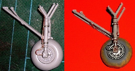 The undercarriage assembly
was assembled per the instructions, I only flattened the tires to ensure a
more realistic sit of the model. I elected once again not to use the brake
lines supplied by Eduard because of the 2 dimensional effect but instead
used these as patterns to fashion ones from copper wire. Brake line
harnesses were fabricated from lead foil and these were super glued to the
inboard oleos. The tow hooks supplied by Eduard were also super glued to
the inboard oleos at this juncture. The entire assembly was painted and
weathered before assembling the individual components. I temporarily
attached the undercarriage to the model and let the entire model sit on a
glass sheet while the glue on the wheels set to ensure that the flat
portion was in full contact with the ‘ground’.
The undercarriage assembly
was assembled per the instructions, I only flattened the tires to ensure a
more realistic sit of the model. I elected once again not to use the brake
lines supplied by Eduard because of the 2 dimensional effect but instead
used these as patterns to fashion ones from copper wire. Brake line
harnesses were fabricated from lead foil and these were super glued to the
inboard oleos. The tow hooks supplied by Eduard were also super glued to
the inboard oleos at this juncture. The entire assembly was painted and
weathered before assembling the individual components. I temporarily
attached the undercarriage to the model and let the entire model sit on a
glass sheet while the glue on the wheels set to ensure that the flat
portion was in full contact with the ‘ground’.
The photo-etched wheel door interiors were fitted to the kit supplied doors with subsequent painting, weathering and dry brushing of the interior surfaces.
TORPEDO
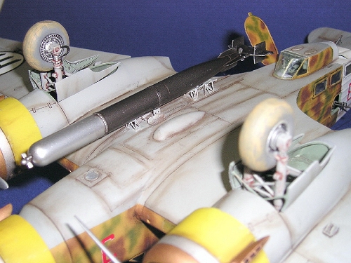 Although Trumpeter
supplied two torpedoes, numerous references indicate that operationally,
the SM-79 only carried one on the port side. The torpedo was assembled
according to the kit instructions and the photo etched details were
subsequently added. The mounting holes in the torpedo were filled with
appropriately sized plastic rod before the entire assembly was painted.
The front portion of the torpedo was sprayed chrome silver and the rest was
gunmetal. References indicate that torpedoes carried by SM-79 came in an
assortment of colour combinations so I allowed myself some artistic licence
here. Once the paint had set, I sealed it with a coat of Testors Metalizer
Sealer.
Although Trumpeter
supplied two torpedoes, numerous references indicate that operationally,
the SM-79 only carried one on the port side. The torpedo was assembled
according to the kit instructions and the photo etched details were
subsequently added. The mounting holes in the torpedo were filled with
appropriately sized plastic rod before the entire assembly was painted.
The front portion of the torpedo was sprayed chrome silver and the rest was
gunmetal. References indicate that torpedoes carried by SM-79 came in an
assortment of colour combinations so I allowed myself some artistic licence
here. Once the paint had set, I sealed it with a coat of Testors Metalizer
Sealer.
The torpedo mounting rack supplied with the kit was discarded and replaced with the photo-etched one from Eduard. Installation proved tricky and I suggest careful alignment before the braces are glued permanently to the underside of the airframe. As this entire assembly was to be the same colour as the undersides, I attached them before painting. One must be extremely careful during subsequent handling as the bits and pieces are very fragile. Remarkably, I did not knock these off during masking, painting, decaling and final assembly!
PROPELLERS
These were assembled per the kit instructions. The spinners were sprayed with Tamiya flat white enamel and the red tip hand painted. Weathering was accomplished with black brown pastel chalk powder with paint chipping simulated with a sliver coloured oil pencil. Testors Dullcote from a spray can sealed everything in. Once dry, the spinner was masked off and the propeller blades sprayed with Humbrol chrome silver. The sliver paint was allowed to dry for two days before the manufacturer’s logo decal was applied. This was then sealed with Model Master Metalizer sealer. The masks were then removed and the propellers set aside for final assembly.
|
CAMOUFLAGE & MARKINGS |
Prior to painting, all parts to be painted were given a good wipe with Jiff kitchen cleaner and subsequently with isopropyl alcohol.
All windows and openings were masked off before the airframe was primed with Mr Surfacer 1200. An inspection was done and any imperfections in filling and sanding were rectified. The primer was allowed to set for 48 hours before proceeding with pre-shading with black on the panel lines.
 The white fuselage band
and rudder cross was sprayed with Tamiya flat white enamel and masked off
when dry.
The white fuselage band
and rudder cross was sprayed with Tamiya flat white enamel and masked off
when dry.
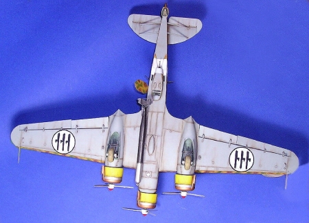
The undersides and wheel doors were sprayed with Model Masters Italian Blue Gray, allowed to set, masked and the top sides subsequently shot with Humbrol 65 Sand. I proceeded to spray the brown mottles freehand using my Testors airbrush with the finest tip (sand coloured). Model Masters Italian Red Brown thinned with 60 percent thinner was used to accomplish this task with frequent cleaning of the nozzle to prevent spatter. Humbrol 112 US Army Green was thinned similarly for the green mottles. When the paint had dried to the touch, all masking was removed and any touch ups were performed with the appropriate colour shot at the offending area with my airbrush.
The engine cowls were painted yellow and when this was dry, the bronze and polished metal areas were masked off and sprayed accordingly.
The entire airframe and cowls were given several coats of Testors Glosscote lacquer in preparation for decaling.
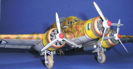
I used Sky Models decals
for one of the versions offered. The painting guide which came with the
decal sheet showed the cowls camouflaged with the unit emblem on the
fuselage sides while the colour profiles in Squadron Signal’s publication
showed a similar aircraft with yellow cowls, no unit emblem and red numeral
‘3’ at the nose. I decided to let artistic license
 overrule accuracy and
chose to amalgamate the two schemes, i.e. with yellow cowls, unit emblem
and red numeral ‘3’ adorning my model. A slightly unusual feature with
this version is that the emblem on the tail is not positioned at the
intersection of the cross but rather slightly above it.
overrule accuracy and
chose to amalgamate the two schemes, i.e. with yellow cowls, unit emblem
and red numeral ‘3’ adorning my model. A slightly unusual feature with
this version is that the emblem on the tail is not positioned at the
intersection of the cross but rather slightly above it.
The Sky Model decals were excellent and went on without problems… well almost. When applying the 278-3 numerals on the fuselage sides, I only realized that these came as discrete digits, including the dash! The absence of carrier film meant that the ‘7’ and ‘2’ folded into an unrecognizable mess as I slid them off the backing sheet. Thankfully after much fiddling accompanied by some choice words, I managed to rectify the mess.
Kitchen cleaner and a damp cloth was used to remove any traces of decal residue and the model sprayed again with another coat of Testors Glosscote.
My usual wash of black-brown water colour/kitchen cleaner cocktail was used to accentuate panel lines and weather the model. Once this had dried, the model was sprayed with Testors Dullcote shot with my trusty airbrush. This was allowed to dry before further weathering was applied with powdered pastel chalks, black brown to simulate general staining and light gray for faded areas. Paint chipping was applied with the sliver coloured oil pencil before another two coats of Dullocote was applied.
|
FINAL CONSTRUCTION |
 I managed to break off the
antennae mast and had this replaced with brass shaped suitably. The
bracing wires at the tail planes/fin were fashioned out of 11 thou steel
guitar string with the spacers represented by lead foil. These were then
painted.
I managed to break off the
antennae mast and had this replaced with brass shaped suitably. The
bracing wires at the tail planes/fin were fashioned out of 11 thou steel
guitar string with the spacers represented by lead foil. These were then
painted.
The loop antennae was an etched item. I managed to completely botch up the item while trying to shape it. I tried to rectify it as best as I could and the photos bear testament of my somewhat futile attempts.
The antennae wires were fashioned from monofilament sewing nylon. There are two sets of these wires originating just aft of the canopy to mid-span of the wing on either side. I realized I made an error only after these were completed. I thought that the slight bumps just aft of the side canopy glazing on either side were the points of origin. It turned out that I was wrong, they should have been slightly lower down.
 The electric generator fan
was attached and a wire originating from the rear pod was fashioned with
copper wire.
The electric generator fan
was attached and a wire originating from the rear pod was fashioned with
copper wire.
The undercarriage and gear doors were super glued in place together with the engines, cowling and propellers.
The pitot tubes were replaced by Evergreen plastic tube heat stretched over 13 thou steel wire and attached to the wingtips with super glue. I did not replicate the strange protuberances on one of the pitot tubes as depicted in the kit as all my references did not indicate the presence of these somewhat dubious appendages.
As a final touch, all flexible machine guns and the torpedo were glued to their respective mountings using white glue. This was a departure from my usual practice of using super glue for these items as I did not want to risk botching up anything at this final stage.
|
CONCLUSIONS |
 I originally planned to
build this kit out of the box. However having seen others’ models of this
aircraft displaying all the innards inspired me to go beyond out-of-the-box
assembly. Moreover, having spent almost two times the money on after
market goodies as compared to the kit itself provided the additional
impetus for such an undertaking.
I originally planned to
build this kit out of the box. However having seen others’ models of this
aircraft displaying all the innards inspired me to go beyond out-of-the-box
assembly. Moreover, having spent almost two times the money on after
market goodies as compared to the kit itself provided the additional
impetus for such an undertaking.
There are several inaccuracies in this kit; the tail plane profile, the cowl openings, the exaggerated fabric effect and the tail plane struts. If one is able to live with these, this kit is quite a pleasant build. If built out of the box, the sparse interior should not be a bother since not much will be visible anyway with the dorsal calm shell and door closed.
While certainly not a competition winner with the imperfections and the glitches on my part, I found this to be quite an enjoyable build. I completed the model in a period of slightly over a year. At SGD 50 (not including the aftermarket stuff), it is certainly a worthwhile bargain.
April 2005
References:
Squadron Signal’s S-79 in action.
If you would like your product reviewed fairly and quickly by a site that has around 300,000 visitors a month, please contact me or see other details in the Note to Contributors.