Classic Airframes 1/48 Re.2001
|
KIT # |
420 |
|
PRICE: |
Probably $29.95 |
|
DECALS: |
See review |
|
REVIEW & |
Lynn Ritger |
|
NOTES: |
` |
|
HISTORY |
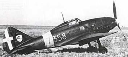
The Re2001 Ariete (ram) was a development of Reggiane’s domestically unsuccessful Re2000, and offered a marked improvement over its predecessor thanks to the inclusion of a license-built Daimler Benz DB601 inline engine. The overall performance of the Re2001 placed it in a class with the excellent Macchi MC.202, but its operational career was limited due to design delays, production backlogs and engine supply issues. With priority given to the Macchi MC.202, the Re2001 was generally relegated to fighter-bomber missions and use as a night fighter. In less than two years a total of 237 (or 242, depending on the source) Re2001s of all variants were produced.
First flight for the Re2001 prototype was in July 1940. Designers Roberto Longhi and Antonio Alessio adapted the fuselage structure of the earlier Re2000 to accept the inline engine, but the wings and tail section were carried over from the earlier design. An early delay was encountered due to the Air Ministry’s objection to the fuel tanks being built into the wings. Several months elapsed before a new design was completed and available for flight test. Following several months of testing, the first aircraft were delivered to three squadrons beginning in June 1941. The aircraft were used chiefly in the Mediterranean and over Italy as night fighters. After the 1943 armistice there were more Re.2001's with the Allies than with Mussolini's forces in the north.
 Development work continued on the basic Re2001 platform in an
effort to maximize the potential of the airframe. One new design featured the
radiators within the wing, which seemed to be an extremely promising innovation.
The first prototype was duly altered and called the Re.2001 bis. Test flights
began in 1941 with Francesco Agello, the world speed record holder for
seaplanes, at the controls. This aircraft flew some 40 mph faster than the
standard model, but was not developed further. Another model (the Re2001 Delta)
utilizing the 840 hp Isotta-Fraschini Delta inverted V-12 was developed and test
flown late in 1942. This work was undertaken in an effort to lessen the reliance
on the Daimler Benz engines. The Delta prototype crashed in January 1943,
however, and the production order for 100 aircraft was cancelled.
Development work continued on the basic Re2001 platform in an
effort to maximize the potential of the airframe. One new design featured the
radiators within the wing, which seemed to be an extremely promising innovation.
The first prototype was duly altered and called the Re.2001 bis. Test flights
began in 1941 with Francesco Agello, the world speed record holder for
seaplanes, at the controls. This aircraft flew some 40 mph faster than the
standard model, but was not developed further. Another model (the Re2001 Delta)
utilizing the 840 hp Isotta-Fraschini Delta inverted V-12 was developed and test
flown late in 1942. This work was undertaken in an effort to lessen the reliance
on the Daimler Benz engines. The Delta prototype crashed in January 1943,
however, and the production order for 100 aircraft was cancelled.
Production of the Re.2001 proceeded slowly. About 40 were built in 1941, a little over 100 in 1942, and the remainder in the first half of 1943. Alongside the original fighter version there appeared a CB model (fighter bomber) and a CN model (night fighter). The CB had a belly bomb rack that could carry a 220 lbs (100 kg) or a 550 lbs (250 kg) bomb. On rare occasions the plane carried a 1,410 lbs (640 kg) bomb. The CN carried two 20 mm cannon in place of the 7.7 mm (0.303 in) machine guns of the standard model. A naval version was also considered which was to have been carried on board the Italian aircraft carriers Aquila and Sparviero, then being designed.
Five aircraft survived the war and remained in service for a few years. Today, there is one Re2001 in storage with the Italian Air Force Museum. The aircraft (MM08071) was ditched in the sea off Sardinia on 11 April 1943 due to engine failure. The pilot, Flight Sergeant Giulio Zangheri escaped with only minor injuries after the ditching. Rediscovered and recovered in 1991, it awaits full restoration. You can learn more about this fascinating aircraft at http://www.fly-net.org/gavs/re2001b.html#inglese.
|
THE KIT |
 |
 |
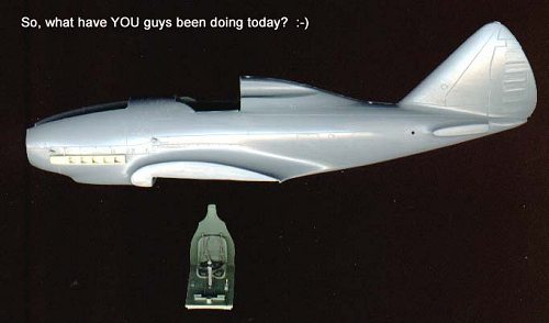
And now, on to the kit. I’ll pull no punches here- this is one of the best, if not THE best, of the Classic Airframes releases to date. I’ve built a few of their other subjects, and each offered its own peculiar challenge to my modeling skills, which is one of the reasons I enjoy their subjects so much. The new Reggiane Re2001, however, went together so fast it made my head spin. That’s not to say that there won’t be areas where you will want to pay attention to what you’re doing- this isn’t a “snap-tite”.
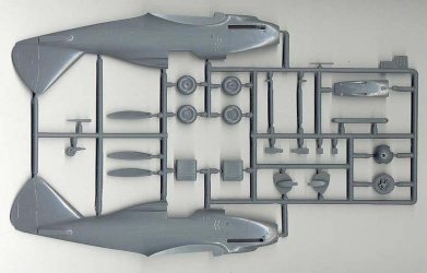
The first thing you’ll note when you open the box and pull the
parts from their bag is the wonderfully understated scribing on the external
surfaces. The quality of the external surfaces has to be seen to be
believed…this is Hasegawa-quality molding, no mistake.
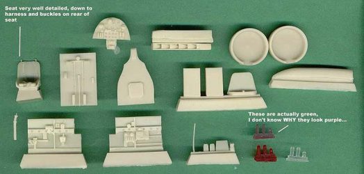
Typical for CA, there are also a number of resin bits contained in a separate
bag. These consisted of all the cockpit components, a pair of nicely done resin
exhausts, several smaller intakes for the nose area, and two circular wheel well
inserts. The bad news on these parts is that true to form for the Czech company
producing the resin parts, there are molding blocks on the back of the plugs…the
good news is that they’re easy to deal with, and nowhere near as frustrating as
those on the Blenheim. All you’ll need is either a razor saw or good coarse
sandpaper…more about this shortly.
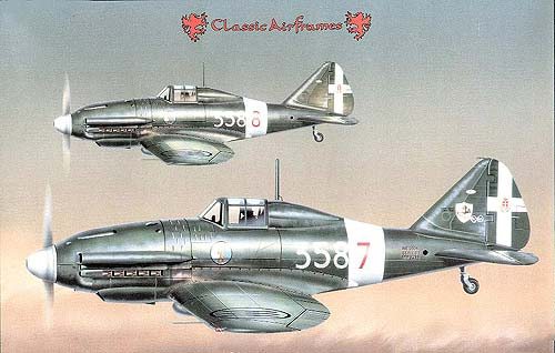
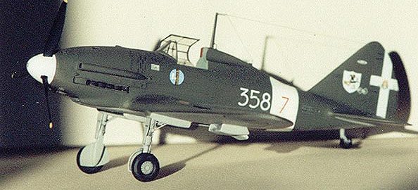
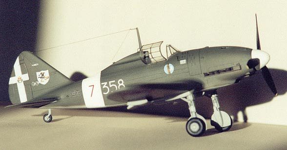
The decal sheet, printed by Microscale, is simply gorgeous, with all colors in
perfect register. Two marking options are on offer, both of which are in fairly
nondescript schemes of dark olive over medium grey (verde oliva oscuro and
grigio mimiteco, for those keeping track). The aircraft represented are MM.7271
of the 362nd Squadriglia, 22nd Gruppo on Sicily in 1942, and MM.7214 flown by
Sergente Maggiore Giovanni Dringoli, 358th Squadriglia, 2nd Stormo. The latter
aircraft is featured on the box art, and was my choice to build as well owing
simply to the fact that it has a white spinner.
 There are also four (!) vacuum-formed canopies included with the kit. The canopy
has actually been the subject of much discussion among several friends; the
opinion was raised that the vacuform canopies represented a “step back” for CA
after seeing their Blenheim canopies. Personally, I’ve never been a fan of vac
canopies myself, but found that I was able to make these work without too much
effort. One
There are also four (!) vacuum-formed canopies included with the kit. The canopy
has actually been the subject of much discussion among several friends; the
opinion was raised that the vacuform canopies represented a “step back” for CA
after seeing their Blenheim canopies. Personally, I’ve never been a fan of vac
canopies myself, but found that I was able to make these work without too much
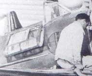
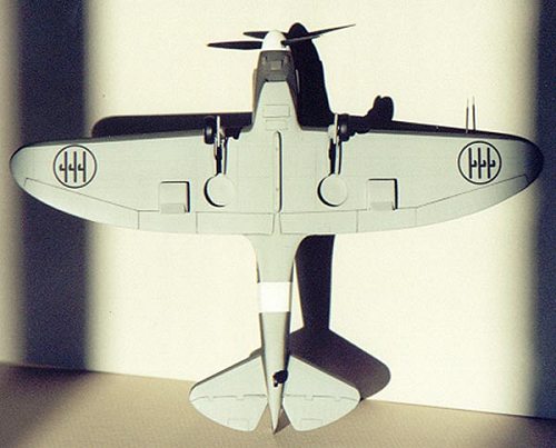
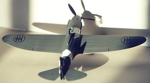
effort. One 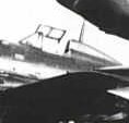 other point to note is that many Re2001s had an interesting
“folding” canopy which hinged down the centerline and collapsed together when
swung all the way to starboard. I have found a photo, however, showing one with
a “standard” canopy, that is to say it is simply swung open to starboard like
that on an Mc202 or Bf109, and it is not collapsed. I have no further
information on this, and would be eager to know if there were indeed two
different canopy styles or if there was a mechanism that allowed the canopy to
remain “intact”, so to speak. Take a look at the two images, since it’s difficult to communicate verbally…
other point to note is that many Re2001s had an interesting
“folding” canopy which hinged down the centerline and collapsed together when
swung all the way to starboard. I have found a photo, however, showing one with
a “standard” canopy, that is to say it is simply swung open to starboard like
that on an Mc202 or Bf109, and it is not collapsed. I have no further
information on this, and would be eager to know if there were indeed two
different canopy styles or if there was a mechanism that allowed the canopy to
remain “intact”, so to speak. Take a look at the two images, since it’s difficult to communicate verbally…
Ok, so now you’re as confused as I am.
A couple of other things to note…first, the kit provides parts to do an early
series aircraft, and does not include the underwing gondolas to build an
Re2001CN night fighter, or the swing arms to make an Re2001CT ground attack
aircraft. The underwing gondolas might be modified from spare Bf109G units for
those so inclined, although I do not have drawings or photos of the Italian
gondolas to confirm this. The new Squadron/Signal book should have further information on this subject. And for those interested, that
wild looking device under the Re2001s in the above photo is a liquid oxygen
bomb.
|
CONSTRUCTION |
Construction of the kit went surprisingly quickly. I don’t always build in the suggested order, instead I’ll often tackle what appear to be the worst or most contentious areas first in order to eliminate the onerous tasks and enjoy the rest of the process. Therefore, the resin bits were first onto the table. I made short work of the pour plugs on the back of the circular wheel well inserts using a finetooth razor saw and a coarse sanding stick (one of several I’ve picked up in the cosmetics section of WalMart…if anyone looks at you strangely when you’re shopping in that section, tell’em you’re playing the part of Dr. Frank N. Furter in a Rocky Horror stage show and they’ll likely leave you alone .) The plugs fit the wings nicely; I did run some 400 grit paper around the circumference of the walls once the plugs were in, and cleaned up the edges of the forward gear bays, but added no additional details owing to my lack of reference materials.
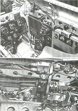 Next up were the cockpit pieces. Have a look at the scan of the
resin parts above, then compare them to the pictures found at
www.amivirtual.com/re2001technical.htm: There is a LOT more detail which could be
added to these parts should the builder so desire; also note the unusual drilled seatpan in the picture immediately above. This style of seat pan was also used
on the French Arsenal VG-30 series of fighters. The CA kit provides a resin
“cushion” premolded on the seat, which gets around this issue nicely. Belts are
molded on the seat as well, and the whole cockpit benefits from a careful wash
and drybrush job. A word about the interior color: CA lists the FS equivalent as
34558, and an article in SAMI mentioned “interior green with a touch of
emerald”, whatever that implies. Not having an FS deck or any emerald lying
about, I simply opted for Model Master British Interior Grey-Green. I presume
that is not the correct shade, but I can live with it, I’ll keep looking for a
closer match for future Italian birds I plan to build.
Next up were the cockpit pieces. Have a look at the scan of the
resin parts above, then compare them to the pictures found at
www.amivirtual.com/re2001technical.htm: There is a LOT more detail which could be
added to these parts should the builder so desire; also note the unusual drilled seatpan in the picture immediately above. This style of seat pan was also used
on the French Arsenal VG-30 series of fighters. The CA kit provides a resin
“cushion” premolded on the seat, which gets around this issue nicely. Belts are
molded on the seat as well, and the whole cockpit benefits from a careful wash
and drybrush job. A word about the interior color: CA lists the FS equivalent as
34558, and an article in SAMI mentioned “interior green with a touch of
emerald”, whatever that implies. Not having an FS deck or any emerald lying
about, I simply opted for Model Master British Interior Grey-Green. I presume
that is not the correct shade, but I can live with it, I’ll keep looking for a
closer match for future Italian birds I plan to build.
Another item to note, and an important one at that: the rear bulkhead does NOT, repeat, does NOT get sandwiched between the fuselage halves. Remove the resin pour plug from the back using your favorite method (mine involves the aforementioned razor saw and sanding stick) and sand it until nice and thin, say around .020. Do not step on it or fold it, it will break . I affixed the rear bulkhead to the floor section with superglue in order to give a more positive location to the seat, which simply sits on two resin blocks, and then used the assembly to draw locator lines on the fuselage halves for the resin walls. I also sanded the mating surfaces of the fuselage halves down as there is a slight ridge near the lip of the cockpit coaming on each side. Doing this and sanding the rear side of the resin walls gives a nice, smooth fit. Be sure to dryfit throughout this process; I had to do so several times and wound up cutting the very lowest stringer off the resin walls in order to get a perfect fit between all the parts. Line up the resin walls with the reference lines drawn by using the floor/rear bulkhead assembly, and then glue the walls into each half.
Once the walls are mounted and painted/detailed to taste, you
may add the instrument panel, which butts up against the forward edges of the
fuselage walls. Note that the panel will also benefit from a careful wash and
drybrush…I use an 18/0 red sable liner to paint the needles on the dials, then
add a tiny drop of Testor’s Clear Parts Cement with a pin to give a “glass” face
to the panel. It’s not hard, and makes quite a difference on the finished
product!
Add the stick and rudder pedals, and the cockpit is essentially complete with
the exception of the gunsight. Once the instrument panel was installed and dry,
I added the resin gunsight. This was enhanced with a light drybrushing, a
“reflector” from a tiny disk of silver Mylar sequin (if you have it, use a #1
punch from the Waldron punch and die set and get a package of these thin, round
mylar sequins in a huge variety of colors from your local Wal-Mart’s craft
section). A sight glass was cut from .005 clear plastic and the gunsight was
done.
 Before you can close up the fuselage halves, however, there’s a
few things up front which need to be taken care of. First of all, now is a great
time to add the resin exhausts. Drill out the very forward edge and square off
the hole (see a pic of a Messerschmitt Bf109E exhaust to see what I’m talking
about), then carefully dryfit the exhausts into their respective slots in the
fuselage halves. I had to elongate the holes at the forward edges to allow the
exhausts to slide in…your mileage may vary. You should also paint and add the
oil cooler at this time. Once it’s in, you’ll think, “Ugh, that roof and seam
looks like crap”…well, I’ve got a foolproof fix for that, too.
Before you can close up the fuselage halves, however, there’s a
few things up front which need to be taken care of. First of all, now is a great
time to add the resin exhausts. Drill out the very forward edge and square off
the hole (see a pic of a Messerschmitt Bf109E exhaust to see what I’m talking
about), then carefully dryfit the exhausts into their respective slots in the
fuselage halves. I had to elongate the holes at the forward edges to allow the
exhausts to slide in…your mileage may vary. You should also paint and add the
oil cooler at this time. Once it’s in, you’ll think, “Ugh, that roof and seam
looks like crap”…well, I’ve got a foolproof fix for that, too.
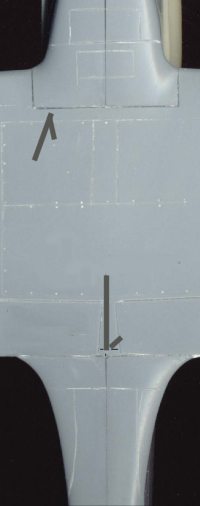
NOW you can close up the fuselage halves. Once again, I carefully dryfit the floor/rear bulkhead assembly in the right fuselage half ONE MORE TIME, then secured the assembly and the halves with trusty ol’ Zap-a-Gap. Seam cleaning followed: I scraped a sharp #11 X-acto blade down the seams to knock’em down first, then followed with the coarse sanding stick, then the fine version, and finished up with 1500 grit wet/dry used wet. To fix that goofy looking oil cooler intake, just cut a strip of .005 styrene sheet wide enough to fit snugly lip to lip in the cooler intake, and superglue it along the leading edge where the strip meets the UPPER lip of the cooler. Once dry, cut off the excess and sand it down…works like a charm, see the overall lower surface photo below.
The upper cowl is next to be added, and you’ll need to drill out the openings for the guns…they are just indentions as provided in the kit. I also added two scratchbuilt MG muzzles; I don’t know if they’re supposed to protrude or not, but I set them up about where they would be on an Me109. If this is wrong, I welcome corrections…not that I’m changing it, but it will be useful for future reference. I also drilled out the semicircular vents around the cowl and scraped open the thin horizontal vents using the tip of a #11 blade; you don’t need to go too deep on those, as you can add a little black wash in there once the plane’s painted and they’ll look just fine. All that done, I superglued the cowl to the fuselage assembly, and cleaned up the resultant seams. A note about the fit here…once again, DRY FIT the pieces and carefully shave down the INNER lip of the fuselage mating surfaces to give a better fit here. Paying a little attention to this will save a LOT of heartache later. Mine went together fine by doing this, but I’ve had instances in the past where the air over my workbench turned a particularly lovely shade of blue thanks to some inept modeling in my part. Ounce of prevention, pound of cure, and all that…
Pay attention when attaching that long intake vent on the port cowling as well…I drilled it a little deeper just to give some depth to it, but in cleaning up the back of it, I got an angle wrong and it wouldn’t sit right on the fuselage. Solution? Add an equal length strip of .010 Evergreen strip at the intersection of the intake and cowl, then sand lightly to make it look like part of the assembly. Is it right? I doubt it…but it looks OK to me, and it looks like it belongs there .
 So, the fuselage is together, and you’ve got these wing parts
laying around…WARNING, WARNING!!! You know that phrase DRY FIT? Well, we’re
going to do it again! Here’s what I did, and I recommend you do NOT follow this
procedure, you’ll find out why shortly. I decided to be smooth and add the lower
wing first, then the upper halves in an effort to minimize seams. “What a great
plan…can’t possibly fail…Wile E. Coyote, you are a super genius!!” You can see
this train wreck coming, right?
So, the fuselage is together, and you’ve got these wing parts
laying around…WARNING, WARNING!!! You know that phrase DRY FIT? Well, we’re
going to do it again! Here’s what I did, and I recommend you do NOT follow this
procedure, you’ll find out why shortly. I decided to be smooth and add the lower
wing first, then the upper halves in an effort to minimize seams. “What a great
plan…can’t possibly fail…Wile E. Coyote, you are a super genius!!” You can see
this train wreck coming, right?
Well, the lower wing has a notch up front which aids greatly in alignment, but
is NOT perfect. I lined it up with that notch, slathered the superglue on,
commenced to cleaning it up, then added the left upper wing…uh oh. Why are the
angles different? The upper wing overlapped the lower wing half with about 4-5
degrees of offset, and this was echoed on the opposite side…what happened, near
as I can tell, was that the lower wing did NOT center properly. I measured it
using the centerline of the wing versus the centerline of the fuselage, and I
got it off by 1/32”. Yes, 1/32” gave the following results:
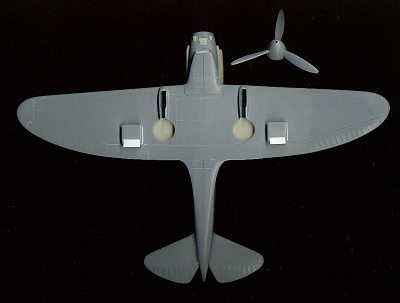
Can you see how the starboard wing (to the left above) leading edge looks to
have more of a tapered leading edge than the port wing? THAT”s what happens. I
managed to knock it down a bit more, and it’s hardly noticeable now, but that
was the worst thing to happen in this entire build. Solution? Assemble the wings
entirely, and dryfit/adjust/fill gaps as necessary when attaching to the
fuselage. The possibility also exists that the wing root fairings were not
molded with proper angles, but as I definitely DID screw up the lower wing
alignment, I can’t conclusively point the finger in that direction…although I
wouldn’t have thought 1/32” would have made THAT much difference.
Ok, the sweating and cursing was over with. The horizontal
stabilizers couldn’t be more straightforward…file the surfaces at a 90 degree
angle on the fuselage and the stabs, then attach with superglue, let dry, sand.
Done. The resin radiators under the wings will need a bit of sanding and
fiddling to make them fit properly in their housings, but this is easy stuff
since the resin is so easy to sand away. One thing I did different was to cut
out the radiator flaps and replace them with .005 card folded to shape…about 30
seconds work total on each, it was really easy to do and it
 looks quite nice
when done.
looks quite nice
when done.
Now, on to the last fiddly bits…prop and gear. The propeller is fairly
straightforward, no big tricks…I assembled the spinner first, sanded and painted
it, then carefully added the blades after cleaning them up. You’ll want to add
tubing to the center of the spinner, otherwise light will shine clear through
the prop blade openings…I used two lengths of aluminum tubing.
The landing gear is another matter entirely. As provided, you get two sticks.
Literally. The wheels are nicely done, although they may look better in resin.
The gear doors are a bit thick, but generally accurate and will benefit from
careful cleaning up. I also added a lip of .010 Evergreen strip around the inner
circumference of the “half moon” doors to give it a little visual interest; pics
I’ve seen seem to show this effect. The legs were detailed in the following
manner:
- Align the legs perfectly even on a rolled up piece of tape (to
hold them in place) but make sure they’ve got at least ¼”- ½” between them.
- Cut a length of lead foil/thick aluminum foil about 1 ½” to 2” long and about
½” wide, and superglue the strip towards the upper section of BOTH legs; let
dry. (To get an idea of the best place to add this, dryfit the gear legs in the
assembled wing halves and mark a line on the leg where it meets the lowermost
surface of the gear nacelle)
- Repeat process, but with a strip only about 1/8” in width and apply about ¼”
beneath the other strip; let dry.
- Cut down the middle of the strips, then take each gear leg and wrap the strips
the remainder of the way around each leg, using a small amount of superglue to
secure the strips; cut away remainder once the leading edge of the strip is
reached.
You now have a bit more detail to work with. I never did find if there are
torque links on the genuine article, so I didn’t add any. I did add brake lines
from silver solder, affixed with strips of lead foil, and once the gear was
installed, I added twin drag struts as suggested in the instructions from
lengths of Evergreen styrene rod. I did add the doors at this point, but did NOT
add the wheels yet…that came after painting.
|
PAINT & DECALS |
 The vacuform windscreen was added next, and this was rather
straightforward…again, DRY FIT the part and VERY CAREFULLY trim the piece with a
NEW #11 blade, this makes a great difference. I wound up using two of the four
canopies in the process; one for the windscreen, and one for the canopy. I
masked the canopy and cockpit off with Scotch tape, then loaded up the ol’
Badger 150 with plain old Testors White thinned with DioSol and shot the white
fuselage band and spinner. After that was dry, I masked off the fuselage band
with Scotch tape, and shot the lower surfaces (gear included) with Aeromaster
Acrylics Grigio Mimiteco (1210), thinned with isopropyl alcohol. I usually don’t
like acrylics, but this stuff stuck like glue, and was dry within 10 minutes! My
kind of paint! Same thing applied to the Aeromaster Verde Oliva Scurro (1214)…by
the time I had the airbrush cleaned out, the whole model was dry and ready for a
glosscoat.
The vacuform windscreen was added next, and this was rather
straightforward…again, DRY FIT the part and VERY CAREFULLY trim the piece with a
NEW #11 blade, this makes a great difference. I wound up using two of the four
canopies in the process; one for the windscreen, and one for the canopy. I
masked the canopy and cockpit off with Scotch tape, then loaded up the ol’
Badger 150 with plain old Testors White thinned with DioSol and shot the white
fuselage band and spinner. After that was dry, I masked off the fuselage band
with Scotch tape, and shot the lower surfaces (gear included) with Aeromaster
Acrylics Grigio Mimiteco (1210), thinned with isopropyl alcohol. I usually don’t
like acrylics, but this stuff stuck like glue, and was dry within 10 minutes! My
kind of paint! Same thing applied to the Aeromaster Verde Oliva Scurro (1214)…by
the time I had the airbrush cleaned out, the whole model was dry and ready for a
glosscoat.
Ok, it’s time to slay a sacred cow here…I’ll say it in no
uncertain terms, Future works great as a canopy enhancer, and I’ve even brushed
it on the upper wing of my F3F-1 as a FINAL glosscoat, but in my experience (and
a LOT of others), it positively sucks as a base gloss coat to which one adds
decals. No two ways about it. Testors Metalizer Sealer is a far superior
product, for a number of reasons:
- It gives a smooth, hard, glossy surface right from the bottle
- It will accept light enamel washes with no adverse effects
- It dries in 15 minutes or less (no more waiting for days for your glosscoat to
dry)
- It does NOT yellow
- It does not react with any enamels or acrylics which I’ve used, and I have
heard of no such reactions from other users of the product
- It is ready to shoot straight from the bottle
 One MAJOR word of caution as regards the Sealer: it is VERY caustic stuff, you
will want to ventilate your work area properly if you use this. I open my window
and set a fan in the window blowing OUT, turned up to high and this works for
me.
One MAJOR word of caution as regards the Sealer: it is VERY caustic stuff, you
will want to ventilate your work area properly if you use this. I open my window
and set a fan in the window blowing OUT, turned up to high and this works for
me.
So, I shot a couple of coats of Sealer on the model, and twenty minutes later, I
was decaling. This is not an exaggeration. The decals laid down wonderfully, and
only required adjustment in one or two areas…when an air bubble or silvering
appeared, I pricked it with the tip of the #11 blade and added a drop of
Solvaset, which took care of the issue. The white is quite opaque, and the whole
decal package was quite a joy to apply. The MM number block has an odd white
shadow offset to it…this is also shown on the box art, so I don’t know if it’s
supposed to be there or not, just consider yourselves advised. Also keep in mind
the oversized Savoy Cross, which overlaps the rudder in all directions and has
arms which are too thick…I wound up painting over the edges of the cross with
the Verde Oliva Scurro (sounds like something you’d order at Olive Garden…). If
I were to do it again, I’d just spray the rudder white when I did the fuselage
band, and mask it with a couple of strips of Scotch tape, then cut the Savoy
crest out of the center of the cross decal and apply it.
After that task was complete, I applied a quick light wash of black enamel in all of the control surface joints, opening panel lines, and vents, then added a coat of Testors Dullcote thinned with DioSol. The propeller was attached, the now-painted wheels were attached, as were the antenna and tailwheel, and the final touch was the previously discussed canopy and antenna wire. Here again, I’ve got a tip for you…according to pics I’ve seen, there was a tensioning spring at the forward edge of the antenna wire where it meets the mast. To simulate this, you will need a hammer.
 What?!
Yep, go to your local auto parts store, and get some auto bulbs with any of the
following part numbers;
1156, 1157, 2057, 3057, 3157
Look through the glass of the bulb…see that filament? That’s what you’re going
after. Wrap the bulb securely in a white paper towel (so you can see the parts
when done), and whack it with the hammer. If done properly, you’ll be rewarded
with a “pop” and the sound of breaking glass. Carefully open the paper towel
(WARNING: BROKEN GLASS INSIDE, in case you needed reminding) and get your
tweezers out. Within the pile of broken glass, you should find the filament
(unless you got lucky and it stayed attached to the stanchions). Extract the
filament, discard the entire remainder of the ex-bulb (WARNING: BROKEN GLASS
INSIDE), and cut the filament in half using your #11 or a set of parts nippers.
Use your favorite antenna making method (mine is stretched sprue), secure the
fin end first, and let dry. Now, slide the filament over the wire, and attach
the leading edge to the antenna mast with superglue, and let dry. Next, apply a
drop of superglue to that joint again, and let the “spring” run up the wire
until it bumps into the drop of superglue. Presto, “instant” tension spring. Run
a leader wire down at an angle to the insulator halfway down the rollover pylon,
and you are DONE!
|
CONCLUSIONS |
There you have it…a blow-by-blow account of how I did it, what I
did, and what you shouldn’t do to get the Re2001 completed. Classic Airframes
has really done themselves proud with this little gem, and building quirks
aside, I can unhesitatingly recommend it to anyone with average modeling skills
and patience
Tauro Decals are available for this aircraft, and you may view the sheet (as
well as some nicely done color profiles) at http://www.karmanet.it/tauromd/Italiano/48565.htm
. Sky Models also does a sheet, 48-017, as pictured below:
Photos in this article were gleaned from a number of websites:
http://www.amivirtual.com/RE2011photo.htm
http://www.amivirtual.com/RE2001technical.htm
http://www.kotfsc.com/aircraft/r2001.htm
http://www.fly-net.org/gavs/re2001b.html#inglese
Copyright ModelingMadness.com. All rights reserved. No reproduction without express permission from the editor.
If you would like your product reviewed fairly and quickly, please contact the editor or see other details in the Note to Contributors.
Back to Reviews Page 2025