Special Hobby 1/32 Fiat G.50
| KIT #: | SH 32056 |
| PRICE: | $68.00 SRP |
| DECALS: | Four options |
| REVIEWER: | Bill Koppos |
| NOTES: | Another nice 1/32 fighter from SH |
| HISTORY |
So you like World War II fighters, eh? Maybe because a lot of them are sleek, good-looking designs that functioned as well as they appeared. "If it looks right, it is right" so it is said. Weeeellllllll the Fiat G-50 may not be for you. As a friend of mine put it, "I'm thinking Flipper ran into a discarded clothes dryer tub." Maybe that's close, but I think it has redeeming features. Well, the later versions anyway. (The early "glasshouse canopy" ones can be overlooked here). From profile the low semi-open cockpit gives it a racer look, the tail aint too bad and the wings were used later on the ultra-sleek Fiat G-55. It's that Godawful engine installation that wrecks things, looking like it just does not belong on the airframe. But the designers were just doing as they always do-compromising. The Fiat A74 14 cylinder radial of 870 horsepower was the only suitable powerplant at the time, used by all Italian fighters of the period. When these airframes were married up to the German Diamler Benz liquid cooled engines later, vast improvement was had. In the meantime, the CR-42, Macchi 200, and our beautiful G-50 soldiered on.
The Fiat G-50 was born in 1937, when it first took to the air at Caselle Airfield in Turin, showing good climb and a speed of 293 MPH, a nice improvement on biplane fighters of the time. Finally conceding to modernity, the all-metal monoplane, retractable landing gear, enclosed cockpit G-50 was ordered into production by the Regia Aeronautica. The first versions sported a large sliding glass canopy hood and a slick spatted tailwheel. They did however, only retain an armament of two 12.7 mm guns. These were sent to Spain for combat testing but arrived too late. By this time most of the Italian pilots were Jonesing for the open cockpits of their previous mounts, and their wishes were answered, a new installation with just a windscreen and half-sides was introduced. The short range of the originals was addressed with an extra fuel tank, this becoming the G-50 bis.
 When Italy jumped into WW2 in June 1940, there were 115 G-50's in
service. Italian Dictator Mussolini decided to get in on the spoils in Europe
and sent an Air Corps to "help" the Germans in the tail end of the Battle of
Britain. The 50 or so G-50's involved were hampered by the lack of range and
radios, and accomplished little. The CR-42 biplanes in use in Italy's North
Arican holdings were running into problems from the RAF's Hurricanes, so G-50's
from 2 Gruppo (I don't know how to do those little "o"s after the Italian Gruppo
numbers, sorry) were sent to Libya. Here, even though the Italians had been
flying in the desert for 6 months, sand filters for their engines were
unexplicably overlooked, and within days the Fiat A74 engines were using more
oil than fuel, due to the fact that sand and sliding pistons don't mix. The
complete lack of radios and any armor plate did not help. Serviceability was so
low, the Squadriglia were sent out in 3's and 4's and the outfit did not last a
month. After 2 Gruppo and others to follow were properly equipped, the results
improved. The Hurricane with it's Vokes sand filter, was not too much faster
than the G-50, and the manueverability of the Italian machine was very good,
though the two-gun armament hurt it too. Throughout 1941 the battles were hard,
the G-50 units doing much low-level strafing and escorting Stukas, both Italian
and German. By June 1942 there were few left. These fighters also fought in
Greece, doing battle against British Gladiators and Hurricanes. Bomb racks were
put on later versions, and G-50's closed out their careers in desperate
fighter-bomber attacks on invading Allied shipping.
When Italy jumped into WW2 in June 1940, there were 115 G-50's in
service. Italian Dictator Mussolini decided to get in on the spoils in Europe
and sent an Air Corps to "help" the Germans in the tail end of the Battle of
Britain. The 50 or so G-50's involved were hampered by the lack of range and
radios, and accomplished little. The CR-42 biplanes in use in Italy's North
Arican holdings were running into problems from the RAF's Hurricanes, so G-50's
from 2 Gruppo (I don't know how to do those little "o"s after the Italian Gruppo
numbers, sorry) were sent to Libya. Here, even though the Italians had been
flying in the desert for 6 months, sand filters for their engines were
unexplicably overlooked, and within days the Fiat A74 engines were using more
oil than fuel, due to the fact that sand and sliding pistons don't mix. The
complete lack of radios and any armor plate did not help. Serviceability was so
low, the Squadriglia were sent out in 3's and 4's and the outfit did not last a
month. After 2 Gruppo and others to follow were properly equipped, the results
improved. The Hurricane with it's Vokes sand filter, was not too much faster
than the G-50, and the manueverability of the Italian machine was very good,
though the two-gun armament hurt it too. Throughout 1941 the battles were hard,
the G-50 units doing much low-level strafing and escorting Stukas, both Italian
and German. By June 1942 there were few left. These fighters also fought in
Greece, doing battle against British Gladiators and Hurricanes. Bomb racks were
put on later versions, and G-50's closed out their careers in desperate
fighter-bomber attacks on invading Allied shipping.
| THE KIT |
SH32056 comes in a large box, which contains 5 sprues injected plastic, a
baggie of "PUR Parts" (Resin, including a really nice engine), a photo-etched
fret, small clear parts bag and a gunsight acetate
 sheet. Decals look nice on
the sheet, including four choices of color/markings to choose from. Cutting some
parts loose one notices the plastic is the usual "soft", shiny SH
stuff, with
nice delicate panel lines. Some panel lines may be TOO delicate, but I prefer
this to "trenches" you sometimes get. The resin engine castings are very well
done with nice finning on the cylinders and bolts on the crankcase. One must
make his own pushrods and ignition wiring though. Instructions are folded paper
with a short history and line drawings.
sheet. Decals look nice on
the sheet, including four choices of color/markings to choose from. Cutting some
parts loose one notices the plastic is the usual "soft", shiny SH
stuff, with
nice delicate panel lines. Some panel lines may be TOO delicate, but I prefer
this to "trenches" you sometimes get. The resin engine castings are very well
done with nice finning on the cylinders and bolts on the crankcase. One must
make his own pushrods and ignition wiring though. Instructions are folded paper
with a short history and line drawings.
There are two sets of cowlings in two halves each, divided into tops and bottoms, one being apparently for the Italian version and the other for the sister Finnish Version also released. Also we find an alternate, shorter tail cone, this one is certainly for the Finn. Well it sure does look like an good one, let's get glueing.
| CONSTRUCTION |
You can start with the cockpit, I started with the wings, partly because I
wanted to get a jump on the bad wing to fuselage fit I was expecting. There are
resin oil coolers to install in the wing roots, these need some trimming and
juggling to get in the right place, otherwise the halves go together nicely.
Taping the fuselage together and trying the wing on for size revealed a surprize-this
thing fits pretty good! This has not been a common thing on previous SH kits, so
g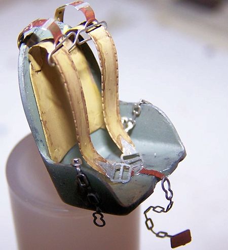 ood-oh. On to the interior.
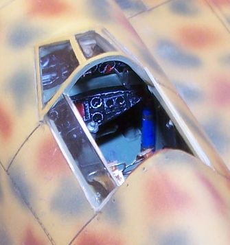
This interior is a mixed bag. The sidewall details are crisp, seat OK and
the rudder pedals are nice resin with etched stirrups. The instrument panel is
another matter, being simplified. References on G-50 interiors proved very
scarce, the only thing I found was a 1/48 Flying Machines kit review with
interior shots, and one picture from the left side that at least confirmed the
IP configuration. SH shows the bottom half just hanging off the top, but in
reality it was a curved panel that jutted out past the top half, and sat at an
angle. One of my pics should give you a good enough idea. I painted this up in
black, white dials, and Future "glass", and installed the etched machine gun
cocking handles. A What looks like an elevator trim wheel is supplied with a
nice etched mounting, but the plans neglect to show you where it goes. The 1/48
review came to the rescue. For the basic color, I used British RAF interior
green, which is the accepted match for the Italian primer, knobs tanks and
switches detail painted in guessed colors. Shading was done with some black
"sludge wash". Not feeling like wrestling with the Italian chain and leather
"bondage" seat harness yet, I left the seat out after checking to make sure it
would fit after fuselage closure. After all this, once the fuselage was glued
together, you really can't see that much of your work through the small cockpit
opening. the
 more adventurous (less lazy than me) of you will find it fairly
easy to open the cockpit side door(s).
more adventurous (less lazy than me) of you will find it fairly
easy to open the cockpit side door(s).
OK, let's see about giving this thing wings. As mentioned before the first test showed a pretty good fit. The only problems were minor gaps at the rear fuselage and in front on the right wing. I installed a styrene strip to the inside fuselage at the rear, to give the wing a more positive mounting surface, and to better hold the cement. Shaving a small amount from the rear wing flat, where it meets the rear fuselage, and the right wing root area, bought things into alignment and Tamiya Extra Thin cement was carefully applied to the seams, being careful not to allow any oozing. I had to run a strip of masking tape from wingtip to wingtip to keep everything good till the glue set up. The results were satisfying. Good job Special Hobby, let's do it on following creations.
Time to tackle the powerplant. Some pics to work from were available on
Google Images. After sawing and trimming each cylinder from the blocks (14) they
were installed on the crankcase, fit being good. 14 pushrods were made from
sprue and fitted to the front row only, as the back won't be visible. Using the
images, holes were drilled in the fitting ( magneto?) on the lower crankcase,
and wires made from thin solder (from Radio Shack) run in appropriate places.
Then the plugs were wired with the solder, just du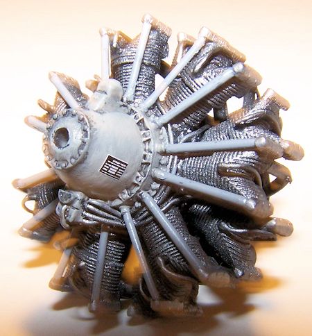 mmied up toward the back where
the ends won't be seen. I painted the whole thing black first for shadows, then Alclad Aluminum. The Crankcase and pushrods were light grey and the whole thing
sludge washed. Ready to install powerplant.
mmied up toward the back where
the ends won't be seen. I painted the whole thing black first for shadows, then Alclad Aluminum. The Crankcase and pushrods were light grey and the whole thing
sludge washed. Ready to install powerplant.
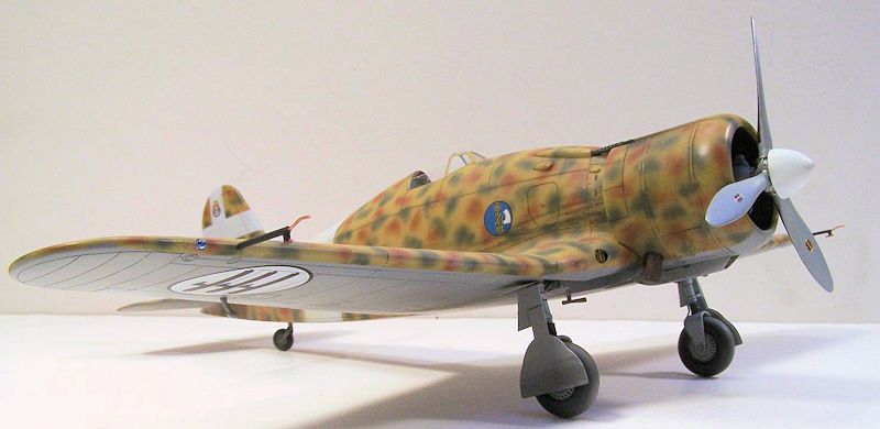
Everything has been sooooo smooth so far, what do ya think is going to happen? Yeah, the poo hit the prop when I went to install the engine and cowling. First, the 2 piece cowling has to be glued together, and the long horizontal seams filled. As said before there are two cowling provided, one , for the Italian version, ours, is supposed to have litle resin bumps glued to it in positions marked with recesses on the cowl parts. These represent bumps in the cowl to leave room for the engine rocker arm covers, but looking at all the pics I could find of this airplane, these appear to be for later versions, most shots having smooth cowling panels. I used the top cowl from the Finnish version, and the bottom from the Italian, and filled in the locator spots with Mr. Surfacer.
The kit provides a resin adapter to join the engine to the fuselage, this being Super-Glued to the engine rear. Now, looking at the sharp angle the front of the fuselage has, when the engine is offered up to the fuselage, it has way too much upward angle. Just attaching this as is will not do. The cowling attachment is no better. The engine is a very loose fit in the cowling, this will not serve to line things up right, and the only place the cowl attaches to the fuselage is at the tab between the machine gun troughs, into an oval slot in the fuselage. Well let's try to sort all this out. Can't have a limited-run kit without at least one challenge.
Setting the assembled cowling on the wing/fuselage shows a least this is
correct the way it sits, based on photos and drawings. I was trying to figure a
lower attachment point when it occurred to me the air intake under the cowl
would hold things in position, as it attaches to the fuselage and the cowl.
Basically the back edge of the cowl should line up with the engraved row of
louvers on the fuselage, and with the top tab in place and the air scoop on,
this is the case. Now that we know where the cowl will sit, the engine angle can
be adjusted to have the prop shaft in the center, by filing off some of the
bottom of the resin adapter. Also in the equation is the depth of the engine in
the cowling, pictures show the front of the crankcase about even with the front
of the cowl. After the resin dust settled (don't
 breathe this stuff, use
caution) about half the insert was gone at about a 30 degree angle. Then I put
in a couple pieces of styrene into the front of the oval fuselage hole for more
mounting surface for the op cowling tab. Wait, there's one more piece to this
puzzle. The exhaust manifold is a horseshoe-shaped item whose lower ends are
the exhaust stubs that jut out of the cowling. The design of the holes in the
cowl won't allow this to be slipped over the exhausts, they must be inserted
from above. So-here's the sequence I used. Test fit engine and cowl-try to
approximate what angle the engine needs to be. Apply some slower drying CA glue
to the engine and attach it. Slip exhaust over engine and let hang loose. Slide
cowling over engine, while on the way sneak the exhausts into the holes and get
cowling into place. Cement upper tab of cowling to the oval slot. Check engine
position and centering. If it looks OK, hold everything straight up until the
cements set. Yep, all this sounds like fun but the only other way would be to
make some kind of spacers to glue to the engine's rocker covers, glue up the
cowl and exhaust, and position the cowl that way. If somebody does that let me
know how it goes.
breathe this stuff, use
caution) about half the insert was gone at about a 30 degree angle. Then I put
in a couple pieces of styrene into the front of the oval fuselage hole for more
mounting surface for the op cowling tab. Wait, there's one more piece to this
puzzle. The exhaust manifold is a horseshoe-shaped item whose lower ends are
the exhaust stubs that jut out of the cowling. The design of the holes in the
cowl won't allow this to be slipped over the exhausts, they must be inserted
from above. So-here's the sequence I used. Test fit engine and cowl-try to
approximate what angle the engine needs to be. Apply some slower drying CA glue
to the engine and attach it. Slip exhaust over engine and let hang loose. Slide
cowling over engine, while on the way sneak the exhausts into the holes and get
cowling into place. Cement upper tab of cowling to the oval slot. Check engine
position and centering. If it looks OK, hold everything straight up until the
cements set. Yep, all this sounds like fun but the only other way would be to
make some kind of spacers to glue to the engine's rocker covers, glue up the
cowl and exhaust, and position the cowl that way. If somebody does that let me
know how it goes.
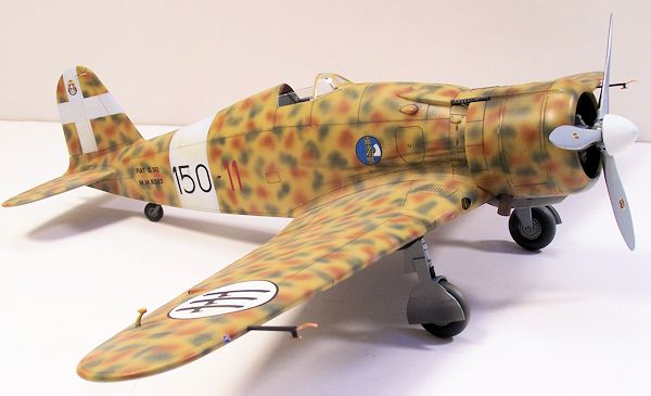
So now the cleaned up resin air scoop can be test fitted and put on, rechecking cowl/engine alignment. The air intake provided is the early, non-sand filtered one, that caused so much havoc to the engines in Libya. The filter equipped intake is a boxy, lumpy affair. My opinion is that both should have been included, but it really would not be that hard to scratch build one. As it is, mine will be a 2 Gruppo machine newly arrived and unfiltered. The stabilizers fit well, needing only minor filling, and I deflected the the nicely done separate control surfaces slightly "up" as seen in refs. The rudder is separated too and poses no problems. Wow-she's ready for paint. The good part is here.
| COLORS & MARKINGS |
Well not so fast. It seems there is no easily gotten stash of Italian airplane
colors out there. The instruction's finishing section gives us the names of the
colors needed...Giallio mimetico 3, Verde Mimetico 2, Marron 3 etc. Mmmmmm, none
of those in my Model Master stash. Stormo! to the rescue, Stormo being an
excellent site all about Italian aircraft. http://www.stormomagazine.com/
So engine and canopy are masked, the lowers shot with Italian blue-Grey
(Model Master has that covered), and masked, leaving the leading edge exposed,
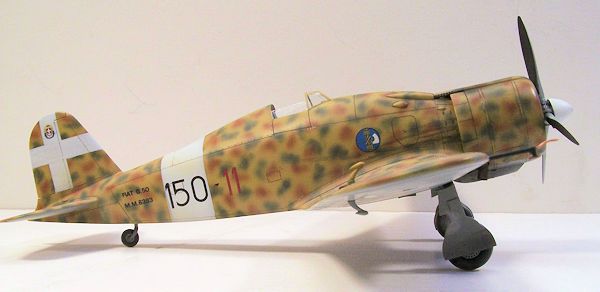
as Italian Camo schemes featured some overlap. Then the uppers got their shot of Koppos Yellow, looking like it fell into a Gulden's Mustard vat when done. But
it matches that Stormo paint chip. Now came 2 hrs of spotting with the rust and
green. Using Model Master thinner with the MM paints allowed me to use my beloved
Paasche H for this job, being able to just push one button to get my small
splotches., instead of pulling and pushing double-action style. I attempted to
make the pattern a bit unev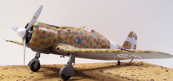 en and random, based on a couple of photos. Each one
was individually done at the factory, so these paint jobs would not be perfect.
en and random, based on a couple of photos. Each one
was individually done at the factory, so these paint jobs would not be perfect.
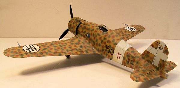
At last I had a spotted pony I could live with. Next day, I masked and sprayed the fuselage band, then the tail crosses. First I laid down a grey coat, to make sure the underlying riot of color would not show through the white. In this vein, I decided to spray white circles under the areas where the Fasces decals would go on the wing uppers, in case these decals ended up being translucent, something that just would not do. The diameter was a handy 1 1/8, perfect for my circle template. At this point I sprayed the whole caboodle with it's glosscoat. Always eager to try new stuff (Not really) I decided to give some Floquil "Hi-Gloss" I found on my LHS shelf. Tests on my poor old Fujimi "Val" test model showed the Floquil Hi-Gloss applied nicely, only needing 2 coats for a very high gloss. However, a full 24 hours (says so right on the bottle) was needed for drying time, unlike my usual Testor's Metallizer sealer, which needs 20 minutes drying time., but takes at least 5 coats to build a gloss. I went with the Floquil because of it's beautiful shine, and waited.
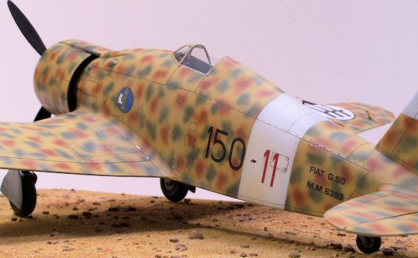
So I started decaling with a bottom wing fasce (?). In case of disaster, the bottoms will show less. The decal behaved well, it did react to Solvaset but it took some time. It needed several applications of Solvaset, and some prodding, to get it to conform to the engraved panel lines. Thankfully, there are few panel lines on this model. The wing tops fit my sprayed white circles just right, "dead on balls accurate". The ones I had trouble with were the fuselage squadron/plane numbers. These were all in one strip with a lot of clear backing, and were thinner than the others. Use a lot of care sliding these into place or they will fold up on you. The rest followed easily, success! The hard parts are done. It is at this point that I apply my panel line enhancements using my water-based "sludge" washes. In this case I used black for the lowers and control separations (ailerons, stabs) and Umber for the uppers. Black was used to create some oil leaks and staining, remember that lack of sand filters thing. Might add more later. There are some louvers on the wing root area and forward fuselage that benefit from a real dark shading. Everything was then sealed in with a final glosscoat. Man ,this thing is looking good!
| FINAL CONSTRUCTION |
Let me refer you to an interesting bit of reference, an Italian wartime
film, "How to build an Airplane", on U-Tube here. http://www.youtube.com/watch?
The landing gear struts are OK, but the video shows rubber boots on the
oleo struts, and I wanted to simulate these. It was easy enough, I just wrapped
some fine solder around the oleo (just above the fork) applied thin CA, and
painted black. The video shows the strut assemblies in various metal shades,
 but
as the finished machine is rolled out they appear to be in some sort of light
grey color. Therefor I figured I would paint them in the some anti-corrosion mix
as the propeller, which was made up from a mix of RLM 65 light blue and
aluminum. The wheels were also done in this and the tires brush painted with
Vallejo paints, a mix of grey and black. Thinned with a bit of water, Vallejo's
are ideal for brushing as they leave no brush marks whatsoever. The photo-etched
outer gear doors L7 and L8 must be installed first, as the rest will cover their
attachment points. Assembled with the main gear doors, which fit nicely, sludged
and installed, the correct rake gauged from the video, I cemented the landing
gear legs in. Brake lines were made from the solder, and installed based on the
film, which also showed the retraction arms (D 15) going into holes in the wheel
well the kit did not have. Carefully I drilled holes in the appropriate place
and painted and attached the retraction arms. Landing gear is hard work!
but
as the finished machine is rolled out they appear to be in some sort of light
grey color. Therefor I figured I would paint them in the some anti-corrosion mix
as the propeller, which was made up from a mix of RLM 65 light blue and
aluminum. The wheels were also done in this and the tires brush painted with
Vallejo paints, a mix of grey and black. Thinned with a bit of water, Vallejo's
are ideal for brushing as they leave no brush marks whatsoever. The photo-etched
outer gear doors L7 and L8 must be installed first, as the rest will cover their
attachment points. Assembled with the main gear doors, which fit nicely, sludged
and installed, the correct rake gauged from the video, I cemented the landing
gear legs in. Brake lines were made from the solder, and installed based on the
film, which also showed the retraction arms (D 15) going into holes in the wheel
well the kit did not have. Carefully I drilled holes in the appropriate place
and painted and attached the retraction arms. Landing gear is hard work!
The propeller is a bit of work too, the 2 part hub being kinda poorly molded, and the separate blades having large mold seams. I cleaned the blades up, then drilled the hub ends for some styrene rod, to create a more solid mount into the ill-defined hub holes. One has to guess his own pitch from pictures too, then a borrowed P-40 prop was used to line up the 3 blades. The hub has a center hole, but no shaft to mount it to the engine hole or line up the spinner, so I made one out of 1/16 rod. Research showed the blades to be a bluish anti-corrosion paint in front, black in back, with an aluminum hub and white spinner. Decals are applied to the blades, spinner sprayed white, and the propeller kit is done.
Remember that seat we put off in step one? Time to deal with it. The Italian WW2 seat harness is a complicated subject, involving double straps and chains (I've heard it called the "bondage" harness.) References are scarce, including none on the G-50 specifically, that I can find. So My depiction is based on a conglomeration of several pictures, diagrams and other folk's models. The colors are based on a shot of a Macchi MC202 interior, front straps and back pad suede, rear straps leather, silver chains. I attached the back straps to the seat rear as per the directions, but I am not at all sure this is correct. At least it looks good and busy to me, so I maneuvered it in and set into a blob of white glue on the seat bracket.
Lesseee what's left? Pitot tubes on Italian AC are also complicated, bending
upward at the end and having a "T" type of thing underneath, in no way
represented by the kit parts. So I made up my own out of styrene rod and wire
(of course there's 2). You know those annoying aileron balances on Me 109's
that are always breaking off? Well the G-50 has 4, handle with care from now on.
The resin 12.7 MG
 barrels are nice, trim the resin at the back leaving a bit
sticking out for attachment into the holes you have drilled under the gun
bulges. The front of the muzzles should be even with the front of the cowl
flaps. We aim these with the resin gunsight, which attaches pretty positively to
a hole in the Instrument panel. A "film" aiming glass is provided to cut out and
white glue to the sight. The windscreen has the side panels attached, these
folded down with the cockpit side doors. Some planes don't show these (pilot
preference?) if you want they are easy to trim off. I left mine on, masked the
minimal panels on the screen, sprayed it Giallo Mimetico and put it on using
White Glue. One of the side panels stuck out so I figured I'd use a touch of
Tamiya Cement to hold it. Bad idea? You Betcha! The side being glued came out
fine but a stray drop got all over the other side, ruining it. I was able to cut
it off carefully, but the right side screen you see is a cheap thin temp until I
get the right size clear to make a new one. At least it missed the windscreen.
Canopies and Koppos do not mix.
barrels are nice, trim the resin at the back leaving a bit
sticking out for attachment into the holes you have drilled under the gun
bulges. The front of the muzzles should be even with the front of the cowl
flaps. We aim these with the resin gunsight, which attaches pretty positively to
a hole in the Instrument panel. A "film" aiming glass is provided to cut out and
white glue to the sight. The windscreen has the side panels attached, these
folded down with the cockpit side doors. Some planes don't show these (pilot
preference?) if you want they are easy to trim off. I left mine on, masked the
minimal panels on the screen, sprayed it Giallo Mimetico and put it on using
White Glue. One of the side panels stuck out so I figured I'd use a touch of
Tamiya Cement to hold it. Bad idea? You Betcha! The side being glued came out
fine but a stray drop got all over the other side, ruining it. I was able to cut
it off carefully, but the right side screen you see is a cheap thin temp until I
get the right size clear to make a new one. At least it missed the windscreen.
Canopies and Koppos do not mix.
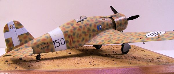
Now the clear parts were masked and the whole shiny thing shot with dullcoat. My Wife was very upset, she rather liked it in glossy mode. Some flat black muzzle blasts were applied to the machine gun business ends, and exhaust areas were blackened. Another flatcoat with some Floquil "Dust" mixed in was applied somewhat randomly, for the Libyan desert effect. Final pieces in the puzzle were the wingtip lights, these required drilling the wing holes much larger. Working with masking tape underneath to prevent "rolling" loss if dropped, I drilled out the lights from the back with a #80 drill bit, enough for a drop of paint to show, right blue, left red. The right one slipped right in, but that damn left, I dropped it twice and amazingly enough found the tiny SOB twice. I mixed up some Tamiya Weathering Stick "Sand" with water and applied some desert splotches, and did some chipping with the Silver pencil. Being an aircraft not in service too long I did not go overboard. I did oil and grunge up the cowling a bit to match a picture, and at last called it done.
| CONCLUSIONS |
This one seemed to take longer than some. The engine work and fiddly bits slowed the build down, but the end result is quite satisfying. The engine installation was the only real assembly problem. Not for beginners but for a modeler of experience, It's something different from the norm and has quite a nice choice of color schemes. OK, Special Hobby, I am ready for the 1/32 Fiat CR-42, a nice follow-up would be a Fokker D-XXI, wouldn't it?
| REFERENCES |
http://www.youtube.com/watch?
http://www.stormomagazine.com/
A History Of The Mediterranean Air War 1940-1945 Vol. One C. Shores and G. Massimello Grub Street London 2012
Italian Aces of WW2 Osprey Aircraft Of The Aces 34 2000
November 2013
If you would like your product reviewed fairly and fairly quickly, please contact the editor or see other details in the Note to Contributors.